MANUFACTURER'S SPECIFICATIONS
FM SECTION
IHF Sensitivity: 1.5 µV. S/N Ratio: 75 dB. Selectivity: 90 dB. THD: Mono, less than 0.2%; stereo, less than 0.3%. Capture Ratio: 1 dB. Image Rejection: More than 110 dB. I.F. Rejection: More than 110 dB. Spurious Response Rejection: Better than 110 dB. AM Suppression: 65 dB. Frequency Response: 20 Hz to 15 kHz +0.2,-2.0 dB mono; 50 Hz to 10 kHz +0.2 dB,-0.5 dB stereo. Stereo Separation: At 1 kHz, better than 40 dB; from 50 Hz to 10 kHz, better than 30 dB. Sub-carrier Suppression: 65 dB.
AM SECTION
IHF Sensitivity: Internal antenna, 300 ILV/meter; external antenna: 15 µV. Selectivity: 40 dB. S/N Ratio: 50 dB. Image Rejection: More than 65 dB. I.F. Rejection: More than 85 dB.
AUDIO SECTION
Fixed Output Level: 650 mV. Variable Output Level: From 70 mV to 2 V. Headphone Output: 1 50 mV into 8-ohm load.
GENERAL SPECIFICATIONS
Power Consumption: 30 watts.
Dimensions: 17 in. W. x 51/2 in. H. x 13 1/2 in. D.
Net Weight: 19 lbs., 10 oz.
Retail Price: $299.95 (including cabinet).
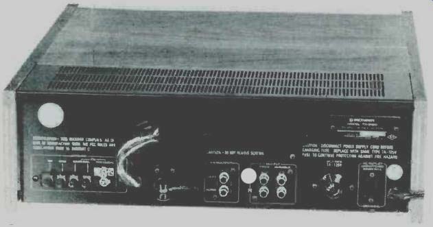
Fig. 1--Rear panel.
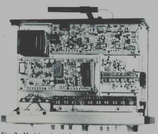
Fig. 2--Modular chassis from above.
Every once in a while we have the pleasure of testing and reporting on a product which is the "best" in its category, regardless of price. The reason why we can call a product "best" every couple of years is because technological developments in this ever improving industry we call high fidelity come so rapidly that last year's "best tuner" is often super ceded by this year's design and production achievements. Such is the case with Pioneer's new TX-9100 tuner. Our laboratory measurements proved performance capabilities for this product which are beyond anything we have ever measured.
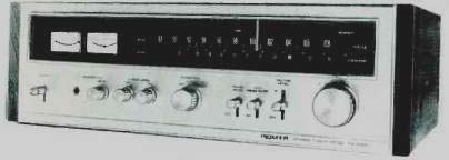
The front panel is made of cast gold-anodized aluminum, and there is an elegantly framed blackout dial area which runs almost the full width of the panel. With power applied, soft blue illumination discloses a long, linear FM dial scale, separate meters for signal-strength and center-of-channel tuning, and a zero-to-100 logging scale. This is the first tuner we've seen which has an AM dial scale which is almost linear (equal spacing between every 100 kHz) as well. Above the dial scale are illuminated designations for AM, FM and Stereo, the latter lighting when a stereo station is received. With the function switch set to AM, the center-channel tuning meter blacks out and only the peak-reading signal strength meter is visible.
The lower portion of the panel contains a lever type power switch, level control for headphones, and separate level controls for AM and FM outputs. The function switch has positions for AM, AUTO-FM (automatically switches from mono to stereo under appropriate signal conditions), and MONO. There are three more lever-type switches which control such circuit features as PULSE NOISE CUT, MPX NOISE FILTER and MUTING. The muting lever switch has three positions-one in which the muting is defeated and the other two for different thresholds of the muting action. A massive tuning knob coupled to an extremely effective flywheel completes the front panel layout.
The rear panel, pictured in Fig. 1, contains terminals for AM and 300 ohm balanced FM antenna connections. In addition, a clever clamp and terminal arrangement is provided for 75 ohm transmission line input. The clamp serves to ground the outer conductor of this kind of transmission line and acts as a strain relief clamp as well. The AM ferrite-bar antenna is pivotable over a 180-degree arc thanks to a ball-joint swivel arrangement which we have not seen in this application until now. There are outputs for fixed-level and variable-level audio (the latter controlled by the individual front panel level controls previously mentioned), outputs for horizontal and vertical inputs to an oscilloscope (for tuning and multipath visual indications), a line fuse holder, and an unswitched convenience a.c. outlet for connection of other equipment.
Normally, when we remove a wood cabinet from a component we expect to see components all over the chassis staring up at us. In the case of the Pioneer TX-9100, every single modular section is neatly covered by a metal shield, with adjustment holes clearly labeled. We removed these covers for Fig. 2, replaced them, and then "went below" and removed the overall bottom cover, disclosing the undersides of various of the logically arranged p.c. modules, as shown in Fig. 3.
There are seven modules in all, not counting the front-end which contains three low-noise dual-gate MOS-FET's used in two r.f. stages and the mixer. Local oscillator voltage is injected via a special buffer amplifier. The largest single p.c. module contains six i.f. limiter stages (IC's are used throughout) and i.f. bandpass characteristics are determined by ceramic filters.
This same module contains a large-scale integrated circuit (which just about handles all the AM reception circuitry), and the FM muting and pulse noise control circuits, about which more later.
Basic multiplex decoding has been reduced to a single IC--but what an IC it is. Motorola's PA-1310P utilizes the phase lock-loop principle to insure rock-stable 19 kHz and 38 kHz frequency and phase. There are no coils or capacitors or "tuned circuits" as we would normally refer to them and, in addition, this circuit reduces residual 38 kHz carrier leakage and its harmonics to undetectable levels. The headphone amplifier module is really a low-power audio amplifier that provides enough power to drive low impedance phones directly, so that you could start listening to this tuner without even hooking up an amplifier and speakers.
Semiconductor complement of the Pioneer TX-9100 includes 6 FET's, 9 IC's, 35 bi-polar transistors, and 27 diodes. Some of those IC's (especially the multiplex phase-lock-loop decoder) contain so many active devices that we gave up counting the "equivalent" number of transistors altogether!
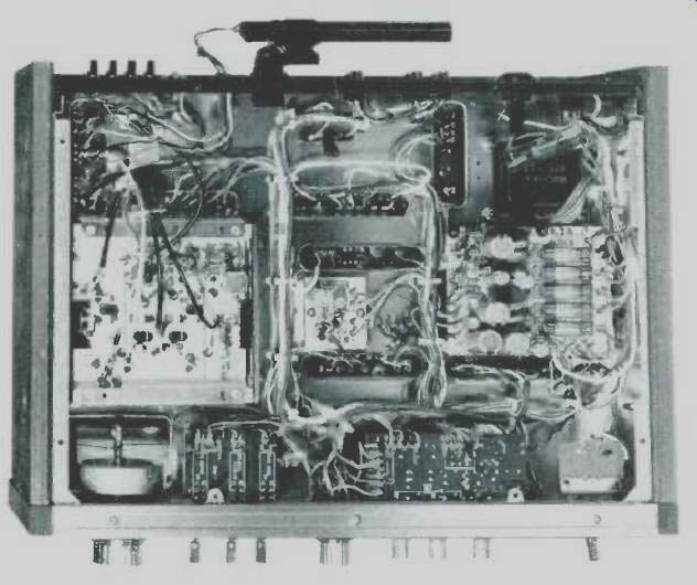
Fig. 3-Chassis from beneath.
FM Measurements
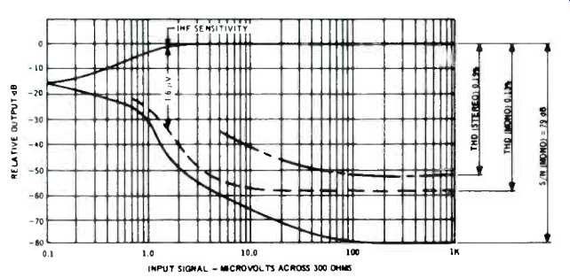
Fig. 4-FM performance characteristics.
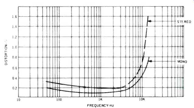
Fig. 5-Distortion vs. frequency.
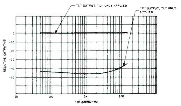
Fig. 6-FM stereo separation characteristics.
Our measurements of the performance of the Pioneer TX-9100 took just about twice as long as normal. That's because we had to repeat each measurement to see if the results were really as good as we measured the first time. They were! Consider, for example, the ultimate S/N ratio, as graphed in Fig. 4. The S/N above input signal levels of 100 µV is an incredible 79 dB. We were delighted to learn that our generator was that good. Its manufacturer, like Pioneer, claims only a 75 dB capability and evidently both ratings are conservative. As for mono THD, it read 0.13% at any signal level above 20 µV, while stereo THD was 0.19%. IHF sensitivity was 1.6 µV and at that level, who's going to argue about one tenth of a microvolt (Pioneer claims 1.5 µV)? Note, too, that the 50 dB S/N ratio was reached with a signal input of just over 2 microvolts. What's more, the low THD figures apply not only at the IHF test point of 400 Hz, but over just about the entire audio band as well, as shown in Fig. 5. THD in mono stays well under Pioneer's claimed 0.2% from 50 Hz to over 5 kHz, rising to 0.8% at the 15 kHz extreme. Stereo THD is under 0.3% over the same range, increasing to 0.8% at 10 kHz. It should be noted that these readings do not differentiate between actual distortion and the presence of "beats" or other extraneous signals. If you have been reading our reviews of tuner products over the past several months you will recall that less than 2% content of extraneous material (THD, beats, sub-carrier residual products, etc.) at 10 kHz is considered something of a miracle. Here we're faced with a product that is more than 6 dB better in this respect than anything we've ever tested!
We have never faulted an FM stereo product that tends to have decreased separation at high audio frequencies, since we feel that anything above 20 dB of separation at the treble extremes is about all most quality cartridges can maintain anyway. Nevertheless, as an exercise in outstanding engineering accomplishment, it's interesting to see what Pioneer was able to do with their phase-lock-loop circuitry in this connection.
Separation characteristics are plotted in Fig. 6 and are actually better than claimed by the manufacturer. Some 40 dB separation or better is maintained from 50 Hz to 10 kHz, and even at 15 kHz, it measured 35 dB! Fantastic! As for those 110 dB figures quoted for image, i.f., and spurious response rejection, we're just going to have to take Pioneer's word for it--our equipment can't read more than 100 dB for these parameters. As near as we were able to judge, however, their capture ratio spec of 1 dB is a bit of an understatement--we measured more like 0.7 or 0.8 dB, though admittedly this is a bit difficult to measure when you start talking about this level of performance. AM suppression did measure exactly 65 dB, as claimed, and again this represents the best we have ever measured for an FM tuner. Selectivity, as measured using standard IHF techniques, turned out to be 95 dB rather than the 90 dB claimed, and frequency response from 50 to 15 kHz was well within 0.5 dB. Interestingly, Pioneer provides an internal switch (accessible once you remove the walnut cabinet) which enables the user to select 50 microsecond de-emphasis rather than the standard 75 microseconds used in the U.S. The smaller time constant is generally used throughout Europe and the Far East. If you happen to accidentally throw the switch to the 50 µsec position, you'll get a bit more treble brilliance in your reproduced music since the highs will be slightly overemphasized.
Listening Tests
While "station counting" really doesn't have too much significance to readers around the country, we could not resist the temptation. In this case, we not only used our outdoor multi-element directional antenna but decided to use our rotator as well--just to see the absolute total we could come up with. Would you believe 67 usable signals? Admittedly, some duplicated the frequency of others (as we rotated the antenna towards different points on the compass), but that proves the importance of a low capture-ratio figure, doesn't it? With the mute switch in the number 1 position (a muting threshold of about 6 uV), that number was reduced to 46. All of which means we were getting some 21 stations at signal strengths of less than 6 microvolts but they were "listenable"! With the muting switch set to the number 2 position, the number of stations logged dropped to 38. The second position has a threshold value of about 20 µV. Muting, by the way, is absolutely positive, since it is relay-controlled. The signal is either there or it isn't--and you have to be tuned to dead center of channel (where you'll get minimum distortion) for the muting to be overcome when it is in operation. In order to check the effectiveness of the pulse-noise cancelling circuit, we retrieved an old electric razor and used it as a pulse noise generator.
(Don't laugh! That was the official "noise generator" used in the FCC field trials held in 1960 to establish stereo FM standards!) In the normal position of the noise-cancelling switch, those "ignition noise" pulses came through (though with admittedly less severity than on most tuners). When we threw the switch the interference was reduced to "whisper level" though it did not, of course, disappear completely. Judging by the severity of the initial interference, this noise cancelling circuit is very effective, and if you are bothered by nearby ignition noises that have not been cured by the use of 75-ohm transmission lines and other "external" cures--this may well be the answer. It works! In fact, everything about this tuner "works"--and works magnificently. You can pay more than $300.00 for some excellent tuners that have additional external convenience features (digital readout of frequency, push button tuning through varactors, etc.) but you can't buy better audible performance than is achievable with Pioneer's new TX-9100 at any price.
-Leonard Feldman
=================
(Audio magazine, Aug. 1973)
Also see:
Pioneer TX-9800 AM/FM Stereo Tuner (Nov. 1979)
Pioneer F-90 Tuner (Jan. 1984)
Pioneer TX-9500-II AM/FM Stereo Tuner (May 1977)
Pioneer Model TVX-9500 TV Audio Tuner (Equip. Profile, Nov. 1978)
= = = =