
by Len Feldman
With the stereo AM/FM receiver component firmly established as the most popular single piece of electronic equipment used for putting together a home music reproducing system, the business of "choosing the right receiver" becomes a fairly complex process. Since a receiver is really three components in one (tuner, preamplifier and amplifier), the prospective purchaser is often faced with a multitude of specifications (since each section requires a complete and defining set of specs) and unfamiliar terms which are intended by the manufacturer to describe fully the features and performance of his product.
There have been suggestions that manufacturers of high fidelity component receivers abandon the time-honored tradition of including technical language in consumer-oriented sales literature and join the "package goods" or furniture console makers in their advertising approach. Generally, this approach consists of a full color brochure, including photographs of slinky models leaning voluptuously on radio phonograph cabinets with facial expressions of ecstasy.
Surrounding these tableaus is a minimum of meaningless verbiage, including such pat phrases as, "Super -powerful amplifier," "Wide-Range Heavy -Duty Speakers," "Ultra Sensitive Tuner," or ( and this one really amuses us by its very combining of unrelated terms) "Powerful Tuner Circuits!"
In an effort to dissuade the longsuffering, legitimate high fidelity component manufacturers from following this "cop-out" course, we present, herewith, a brief ( and, we hope, succinct) lexicon of terms used in describing high fidelity receivers. These, arranged alphabetically, will include both specifications and physical-feature terms and phrases. Armed with this pocket dictionary (it is pocket sized, if you fold these pages a sufficient number of times ), you can walk into any high fidelity dealer, read any manufacturer's specification literature and, hopefully, select and buy the right receiver for your needs and budget.
As already mentioned, the terms are arranged alphabetically. In addition, those which are considered to be SPECIFICATIONS will be capitalized, while those which represent features other than specs will appear in lower case letters. We have attempted to cross-index as many of the terms as possible, since some of you may attempt to look up "Separation, Stereo," while others may try to find the definition under "Stereo Separation" and still others may seek the same information under "FM Stereo Separation." We promise that at no time will you be asked to look up "Controls, Tone" after first attempting to find it under "Tone Controls," and then be told to refer again to "See Tone Controls." One other thing. For those who prefer pictures to words, where ever possible we have set alongside the most important specifications a graph designed to show you how a particular spec works out in practice and what we consider to be good numbers for that spec. Such graphs are necessarily subjective (on our part) and the demarcation lines between "Poor," "Fair," "Good," and "Excellent" should not be taken as the last word. They are, rather, a suggested guide for quality selection of receivers and can be tempered by budget considerations as well as the advancing state of the art.
Finally, where conventional dictionaries tell you whether a word is a noun, adjective, adverb, etc., we have substituted the abbreviations (A ), (P ), and (T) . The appearance of (A) after a term means that the term is primarily associated with power amplifiers. A (P) appearing after a term means that the term relates to the preamplifier section of a receiver, while a (T) denotes a term related primarily to tuners or tuner performance.
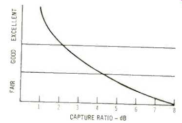
Fig. 1--Capture ratio ratings
Antenna Input Impedance (T). This term describes the type of transmission line or "lead-in" cable that should be used with a given tuner input. The two most popular impedances are 300 ohms ( for which twin -lead, flat antenna wire similar to that commonly used for TV sets is used) and 75 ohms (in which case coaxial cable-one conductor inside a shielded outer conductor--is used). Some tuners feature both popular impedances so that either type of transmission line can be used. In the event that you must use, say, 75-ohm cable to connect to a 300 -ohm antenna input on a receiver (or vice versa ), some diminution of signal transfer will occur, but in all but the most fringe -signal areas, the mismatch is not terribly severe.
Balance Control (P). See Volume and Balance Controls.
Bandwidth, Power (A). See Power Bandwidth.
CAPTURE RATIO (T). The ability of an FM tuner to select the stronger of two FM stations when both are transmitting at the same frequency. While the FCC does not normally assign identical
frequencies to closely located stations in a given geographical area, a strong station many miles away might produce a signal strength at the antenna terminals of a tuner which is not much weaker than that of a low -powered local station which you may want to hear. Therefore, the less difference in strength between two stations required for the stronger station to obliterate the weaker, the better the capture ratio of the tuner. Capture ratio is expressed in dB, and the lower the figure, the better the capture ratio.
See Fig. 1 for qualitative ratings.
CONTINUOUS POWER (A). See RMS POWER (A). DAMPING FACTOR (A). The modern power amplifier, by virtue of the large amounts of negative feedback applied to it, is considered to be almost a "constant-voltage" source. This is another way of saying that it's internal or "looking-back-into" impedance is very low.
Damping factor is simply the ratio of the loudspeaker impedance to the "looking back-into-the-output" impedance of the amplifier. Thus, if an amplifier has an internal impedance of 0.5 ohms and is to be used with a loudspeaker having an impedance of 8 ohms, the damping factor of this combination will be 8/0.5 =16. High damping factors generally result in "tighter" bass reproduction, since the low impedance across the terminals of the loudspeaker tends to limit any undesired "overshoot" on the part of the loudspeaker cone. The use of overly long speaker wires between amplifier and speaker (of insufficiently heavy gauge) can seriously reduce the effective damping factor, since the loudspeaker then "sees" the combination of amplifier internal impedance plus the series resistance of the speaker wires themselves.
DISTORTION (A, T). See IM Distortion and THD (TOTAL HARMONIC DISTORTION). Equalization (P). In making recordings, a deliberate amount of frequency response alteration is introduced. The bass or low -frequency region of the spectrum is always under -recorded to prevent unduly large groove undulations ( bass energy is greater than mid- or high-frequency content) from destroying groove walls. Conversely, higher frequencies are deliberately emphasized to improve the signal -to -high -frequency surface noise of the resulting disk. In the playback process, inverse frequency correction must be built into the preamplifier section, so that the net frequency response will be "flat." Standard amounts of correction should conform to the so-called RIAA curve, as shown in Fig. 2. RIAA stands for the Record Industry Association of America. A similar technique is used in FM broadcasting, in which the high frequencies are deliberately emphasized during transmission and de-emphasized during reception to improve the relative signal-to-noise between the program content and the high -frequency background noise common to wide -band FM. The term DE -EMPHASIS, rather than equalization, is used in describing this FM equalization technique, and the characteristic curve is shown in Fig. 3.
Filters (P, T). High-frequency and low frequency filters are often incorporated in the preamplifier section of receivers.
The former generally cut out high-frequency response at a steeper rate than do conventional tone controls. It is thus possible to eliminate record scratch and high -frequency hiss more effectively with less sacrifice of program content. Low frequency filters are similarly constructed to eliminate such problems as turntable rumble without seriously affecting bass response required for proper musical reproduction. Recently, band-pass filters have appeared in the i.f. circuits of FM tuner sections, replacing previously used dual -tuned interstage transformers. Such crystal and ceramic filters (as well as multi-pole inductive-capacitive filters ) are said to provide better control over the bandpass characteristics of the i.f. section of the receiver.
FM De-emphasis (T). See Equalization.
FM Limiting (T). See Limiting, FM. FM STEREO SEPARATION (T). The degree to which an FM tuner is capable of rejecting "left -channel" information from its right -channel output and "right channel" information from its left -channel output is called FM Stereo Separation. It is stated in dB. Because the stereo FM decoding process is quite complex, separation is usually not uniform at all audio frequencies. It tends to be best at mid frequencies, falling off somewhat at low frequencies and even more so at high frequencies. See Figs. 4 and 5 for qualitative ratings. Most manufacturers state stereo FM separation at mid -frequencies such as 400 Hz or 1000 Hz, though some present complete separation curves or plots, such as that shown in Fig. 6.
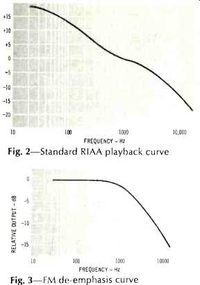
Fig. 2-Standard RIAA playback curve
Fig. 3-FM de -emphasis curve
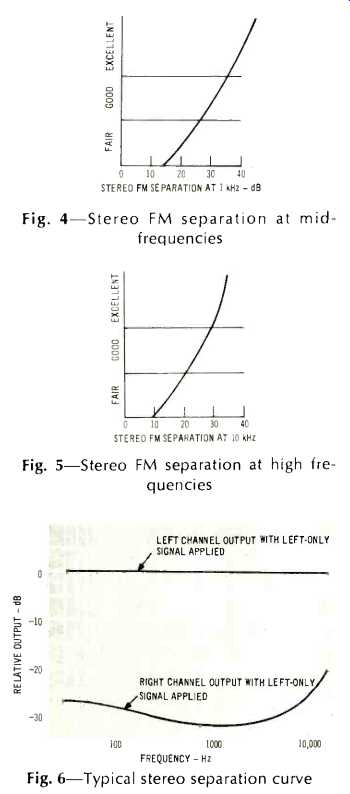
Fig. 4-Stereo FM separation at mid frequencies
Fig. 5-Stereo FM separation at high frequencies
Fig. 6-Typical stereo separation curve
FREQUENCY RESPONSE (P, A, T). One of the most fundamental descriptive specifications for all parts of the receiver, frequency response is usually stated as the extremes of frequency at which response is uniform within a stated number of dB. Thus, "Uniform from 20 Hz to 20,000 Hz within ±1.5 dB" might be a typical statement of this specification. The greater the frequency extremes and the lower the "±dB" figure, the better the response. There are two schools of design philosophy with respect to amplifier frequency response, however.
Some maintain that the wider the response, the better, and feature such specifications as "5 Hz to 100,000 Hz," while others maintain that the response should be limited to the total range of human hearing, namely 20 Hz to 20,000 Hz, and that increased bandwidth beyond that contributes no improvement and may even be disadvantageous in certain respects. With respect to FM tuners, it should be noted that broadcast transmissions are limited to a top frequency of 15,000 Hz. Thus, the publication of a tuner frequency response which is limited, to this top frequency in no way denotes an inferior product. Because of the above mentioned differences in opinion regarding frequency-response requirements in high fidelity, no qualitative rating is presented for this specification here.
Fuses (T, P, A). Protective fuses may be found in power lines of receivers as well as in speaker output circuits of the amplifier portions of such receivers. Placed in the power -line circuit, fuses prevent costly burn -outs of expensive components in the event of power supply failures etc. Placed in speaker lines, fuses protect output transistors in modern, solid-state receivers. They are meant to "blow" if excessive current is drawn from output circuits-as for example, when speaker leads inadvertently cause a short circuit across the output terminals of a receiver.
More recently, protective relays and thermal circuit breakers are finding increased use in such applications. In replacing any fuse, always replace with a fuse of identical rating. To do otherwise voids most manufacturer's warranties and is an invitation to costly repairs and damage to the receiver.
Headphone Jack (P). A popular feature of nearly all stereo high fidelity receivers, the stereo headphone jack enables listeners to enjoy stereo in complete privacy, without disturbing other members of the family. Usually, a selector switch enables the listener to turn off the loudspeakers entirely while using the headphones. In some receivers, the insertion of the headphone plugs into the headphone jacks accomplishes the loudspeaker disconnect. Normally, little power is required for loud -level listening via headphones as compared with speaker listening. Suitable headphones are sold in a wide range of price categories. Two characteristics to watch for when purchasing this accessory are wearing comfort and fidelity. Low-frequency response can be a function of tightness of fit around the ears, and since not all ears are "built alike," headphones should be tried for fit and comfort as well as tonal performance.
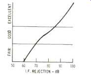
Fig. 7--Ratings for FM i.f. rejection
HUM (P, A). See NOISE and HUM. I.F. REJECTION (T). The ability of a tuner section to reject signals of the intermediate frequency (generally 10.7 MHz, in the case of FM tuners). Conceivably, there may be transmissions by radio sources at these frequencies (short wave, etc. ), which should not be detected by a good FM tuner. Measured in dB, the higher the i.f. rejection specification the better. A qualitative rating is shown in Fig. 7.
IHF SENSITIVITY (T). The number of microvolts of FM signal which must be applied to the antenna terminals of an FM tuner so that the program peaks heard will be 30 dB louder than any background noise and distortion. This number will be lower in better sets, higher in inferior sets. While 30 dB of signal-to-noise-and-distortion ratios do not constitute a good' listenable signal, this measure is used to denote the least usable signal and is the most significant comparison spec that can be applied for tuners. Do not confuse this specification with "Quieting Sensitivity," an older spec which only required that the noise be 30 dB lower than the signal and did not take into account the resulting distortion level-which is of equal or perhaps even greater importance. Figure 8 presents a qualitative rating chart for IHF sensitivity of modern tuner sections. IHF stands for the Institute of High Fidelity, which promulgated this and related specifications and ratings for tuners and amplifiers. The IHF consists of manufacturers who specialize in high-quality high fidelity component product design and manufacture.
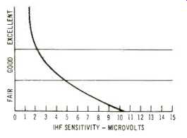
Fig. 8--Ratings for IHF sensitivity
IM DISTORTION (T, P, A). While there are many forms of audible distortion that can be produced by electronic amplifiers or tuners, the one thought to be the most objectionable to the listener is called IM, or intermodulation distortion. This form of distortion consists of the reproduction of sum and difference frequencies arising from the non-linear mixing of two desired frequencies. As an example, the frequencies of 60 Hz and 7,000 Hz, present simultaneously in a given audio program, may produce small amounts of 7060 Hz and 6940 Hz which are not present in the original program. IM distortion is expressed as a percentage of the total audio information present, so that the lower the percentage, the better the equipment. See Fig. 9 for a qualitative rating of IM.
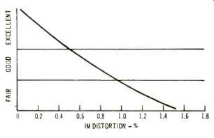
Fig. 9--Ratings for IM distortion
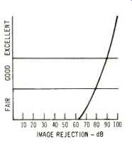
Fig. 10--Rating for image rejection
Image Rejection (T). In an FM tuner, the local oscillator is tuned 10.7 MHz above the incoming signal. When the incoming signal beats with the local oscillator, the desired 10.7 MHz i.f. signal is created for subsequent amplification and detection by the i.f. system of the tuner.
Take, for example an incoming signal at 100 MHz. When the tuner is tuned to this signal, the local oscillator will be at 110.7 MHz and the required 10.7 MHz will be derived. However, an incoming signal at 121.4 MHz (10.7 MHz higher than the local oscillator) might also "beat" with the local oscillator to produce a signal at 10.7 MHz. While 121.4 MHz is outside the FM frequency band, it is within certain aeronautical frequency-band assignments and you don't want to hear airline pilots' conversations mixed in with your FM musical listening. Image rejection is the ability of a tuner to reject undesired frequencies which have a mathematical relationship to the i.f. so that they might be present in the output of the receiver.
Expressed in dB, the higher the figure, the better the specification. See Fig. 10 for a qualitative analysis of this specification.
Impedance, Antenna (T). See Antenna Impedance.
Indicator Light, Stereo (T). See Stereo Indicator Light.
Input Impedance (P, A). The various input impedances listed in connection with the input facilities of a receiver are of an informational nature, designed to help you in the selection of matching components, such as cartridges, tape players, etc. Generally stated in "ohms," the input impedance is usually stated for phono, aux, and tape inputs on a receiver. For example, the magnetic phono cartridge input impedance on most receivers is characteristically designed at 47,000 ohms, because most magnetic cartridges work best into that value of impedance.
If, for example, you were considering the purchase of a phono cartridge and found that it requires an input impedance of, say 100,000 ohms for best response, you could expect some deterioration in frequency response if you attempted to plug that cartridge into a phono input having a 47,000 -ohm impedance.
INPUT SENSITIVITY (P). This specification is provided as an aid in selecting matching components that will work compatibly with the receiver of your choice. The auxiliary inputs of your receiver may have an input sensitivity of 250 millivolts. If you planned to feed the output of a tape deck to this input, you would choose a tape deck having a similar output. If, for example, your tape deck only provided 100 millivolts of output, you would never be able to drive the amplifier section of your receiver to full power output. Input sensitivities are usually given for all available inputs located at the back of the receiver, such as phono, tape, aux, and so forth. Phono inputs have sensitivities of the order of a few millivolts and are considered "low-level" inputs. Inputs such as tape and auxiliary will have sensitivities of the order of fractions of a volt and are referred to as high-level inputs.
Limiting, FM (T). It is the limiting characteristic of an FM tuner circuit that largely makes FM the "static -free" program source that it is. Limiting is accomplished by circuits called "limiters," which literally "slice off" the upper and lower extremities of the r.f. or i.f. signals after sufficient amplification has been accomplished. In FM, the ultimate amplitude of the signal is unimportant. It is the changing frequency which determines audio recovery, so that limiting the amplitude of the signal prior to detection serves as a means of removing any amplitude variations which might have been present. Most noise and static is of an amplitude nature and the limiting action therefore slices off this noise as well.
While only a few manufacturers describe the limiting characteristics of their products as a published specification, this characteristic is of extreme importance and can have as much to do with superior FM performance as IHF sensitivity.
Limiting, when stated, will be in number of microvolts required for "full" limiting (or, sometimes, for "1 dB limiting" which means that the signal amplitude is within 1 dB of its final, highest value). The lower the figure, in microvolts, the better the characteristic. A qualitative chart of this characteristic is shown in Fig. 11.
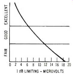
Fig. 11--Rating for full limiting
Loudness Control (P). Human hearing tends to fall off at the extreme low- and high-frequency ends of the audio spectrum. The effect is more pronounced when we listen to music at low loudness levels--or lower than in original performance.
Since much of our home listening is done at lower levels than would be experienced in a concert hall, a loudness control (sometimes called loudness -contour control)
serves to compensate automatically for this hearing deficiency at low levels. When the control is advanced to high settings, little or no compensation is afforded. As the setting is reduced, more and more compensation is added. Since levels of program sources differ and the degree of compensation in different people's hearing also differs, most loudness controls are equipped with a switch enabling the listener to defeat this feature and to restore the control to its more usual function as a regular volume control.
Low Frequency Filter (P). See Filters Meters (T). Many of the better receivers are equipped with one or more tuning meters, to assist the user in accurately selecting desired FM (or AM) stations.
Two types of meters are commonly used: the peak -reading tuning meter and the center -of -channel tuning meter. The former is used by tuning in to the desired station and finding the highest reading of the meter. The reading often provides a fair indication of signal strength when used this way. The center-of-channel meter has its pointer normally resting at mid-scale. As a station is approached, the meter will swing widely to one side. As center of channel is reached, the meter will once again be at mid -scale and, if the center of channel is passed over, the needle will swing to the other side of the meter scale. This type generally enables the user to tune more accurately to center of channel than does the peak -reading type, but it gives no indication of actual signal strength, nor is it applicable to AM tuning, as is the peak-reading type. Some modern receivers are equipped with both types of meters. Still other designs make dual use of one meter ( the peak -reading type) enabling the user to read relative multipath interference ( see Multipath ) and adjust his antenna orientation for minimization of this form of distortion.
Monitor, Tape (P). See Tape Monitor.
Multipath Distortion (T). While not, strictly speaking, a "feature" or a "specification" of receivers, multipath is an important term whose significance should be understood by owners of stereo FM receivers. It is completely analogous to "ghosts" in TV reception. Reflected signals ( from nearby man-made or natural structures) arrive at the receiver's antenna terminals a small fraction of a second later than the direct FM signal. The result is a form of distortion ( particularly noticeable when listening to stereo FM) which is characterized by sibilant "s" sounds in speech, loss or wandering of stereo separation, and often even added harmonic distortion (see THD). Multipath distortion can be minimized by careful orientation of an outdoor directional FM antenna.
MUSIC POWER (A). One of two accepted forms of statement of the power output capability of the power amplifier section of a receiver. This specification is sometimes called IHF power and means the same thing as Music Power. Musical crescendos are often of very short duration and most amplifiers can deliver somewhat more power for short periods of time than they can for long, continuous periods.
Since most listening is musical, it is felt that the "Music Power" rating has somewhat greater bearing on the useful power capability of an amplifier. Prior to the development of this modified power specification, all power was quoted as Continuous Power or R.M.S. Power. ( See R.M.S. Power.) There is no direct correlation between continuous power and music power, except that the latter will generally be somewhat higher than the former. The difference depends in large measure upon the design or ruggedness of the power supply used in a particular receiver. The better the regulation of this supply, the closer the two ratings will be.
=============
(Audio magazine, Sept. 1970)
Also see: