Stylus Velocity and Making Records
Dear Sir:
I read your June, 1976 issue of Audio and would like to clarify the question and answer sequence in "Audioclinic" referring to measurement specifications for phono cartridges and to add some data to Mr. Cousino's article, "Making Records." Inasmuch as "stylus velocity" as a concept applies equally well to either a cutting stylus or a playback stylus, I would like to refer to a system of standards in daily use by the disc-cutting profession in the U.S. In the early days of long playing microgroove recording for home consumption, RCA Vic tor developed a set of record--reproduce frequency response equalization curves known simply as "new orthophonic" recording characteristics. There was, and still is, in the recording mode bass cut and treble boost, with a matching bass boost and treble cut in the reproduce mode.
Since how much bass cut and treble boost had to be specified against a known reference point, 1000 cycles per second was chosen (1 kHz in modern "audio-ese"). Just why 1 kHz was selected is not too important here; the importance lies in the fact that a standard reference frequency was selected and is still adhered to.
RCA Victor recorded, pressed, and distributed a 10-inch "new orthophonic" frequency test record which was designed to assist users in adjusting phonograph record reproducers to the proper response for playing the "New Orthophonic" records. The records commercially released using this scheme of equalization were a big success, and soon other record companies were interested in adopting this scheme. In fact, it was so successful that the whole concept was adopted by the recording industry and is now the famous "RIAA curve." In 1964, the NAB (National Association of Broadcasters) issued its NAB Test Record, which was the same as the RCA disc with a few important additions, some of which follow.
First, and most important of all the new features, is the statement that the 1 kHz, 0 VU reference level tone is lateral modulation (we're now in the stereo era of 1964) and generates a peak stylus velocity of 7 cm/sec.
Other additions and changes from the original RCA disc have to do with cutting in the stereo mode: Left channel only (channel "A" or "1"), right channel only (channel "B" or "2"), both channels together in phase (lateral modulation or mono), and both channels together with 180° phase reversal (vertical modulation, first used in cylinder phonograph records).
Another feature of this disc is that the overall recorded level is 2 dB higher than the RCA disc, due primarily to improvements in cutterhead technology.
Now, let's return to the first of the new features of the NAB test record-the business about the 7 cm/sec. peak velocity, lateral modulation. An interesting sidelight of this discussion is that there is no mention of any kind of stylus velocity any where on either the record jacket or label of the RCA disc. The 0 dB, 1 kHz level is 2 dB lower than the NAB standard and is 5.5 cm/sec. peak velocity and is, of course, pure lateral modulation, having been cut with a mono cutterhead.
Now, let's look closely at the words and symbols contained in the expression "7 cm/sec. peak velocity, lateral modulation," and analyze the parts of that expression bit-by-bit.

In dealing with the sine wave tests, which both records contain,
two terms normally come to mind "peak" and "rms" (root
mean square). The term "peak" or highest has to be self-explanatory,
but not all readers know how to calculate rms values. Rms is the product
of peak value x 0.707, which when dealing with the 7 cm/sec. peak velocity,
lateral modulation, comes out to be 4.949 cm/sec. rms velocity, lateral modulation.
This figure is commonly rounded off to 5.0 in most literature.
Lateral modulation is mono modulation, parallel to the surface of the record and, as such, indicates that both channels of the cutterhead are driven equally in all respects. Seen in this light, it follows that mono is a special case, with both channels doing the same thing at the same time. Another special case of stereo is the situation when one channel does nothing at all, and the other channel is driven.
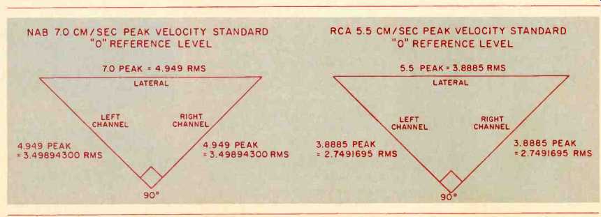
In the case of the NAB test record, the remaining channel is driven at 0 reference level at 1 kHz. Due to the basic design of stereo cutters and playback cartridges, wherein the two planes of modulation, as well as the two groove walls are at right angles (90°) to each other, it then becomes possible to solve an isosceles right triangle (shades of high-school Geometry I1) for either leg, with the hypotenuse equal to 5.0 cm/sec. rms (or 4.949 to be more ac curate). Using 4.949, the value equals 3.49894300 cm/sec. rms, usually rounded off to 3.5 cm/sec. rms. This value represents the rms velocity for each channel. If a person chooses to compute the per-channel velocity using an already rounded-off hypotenuse value (rms lateral modulation) of 5.0, instead of the more accurate 4.949, the per-channel velocity is 3.535. At this point, some of the numbers alluded to in the original question in "Audioclinic" begin to look somewhat familiar. In order to more clearly illustrate the values, both rms and peak, there is included here a set of isosceles right triangles, one with RCA values and the other with the NAB values. In today's mastering, the NAB 7 cm/sec. peak velocity, lateral modulation, is the most widely used.
I think one can see from this discussion that a few standards need to be clearly recognized, stated, and adhered to by phono cartridge manufacturers, printers and proofreaders of phono cartridge advertising literature, phono cartridge reviewers, testing facilities, technical writers, and all other of us who influence the thinking and reasoning of the many readers who are searching for a little bit of the truth. I hope that the cartridge "numbers game" of velocity vs. output may now be a bit easier to work with when comparing differing devices.
I would also like to comment on a portion of the article "Making Records" by Ralph Cousino of Capitol Records, appearing under the sub head "Master Disc." I'm sure he knows the facts, probably better than I, but the wording can lead the reader astray. Quoting R.C. now, "Because it will adhere to the lacquer surface, silver is used as the first agent. On top of the silver goes a thin coating of nickel, deposited by dipping the silver-coated disc into a nickel solution." While it is necessary that the silver adhere to the lacquer surface, so would peanut butter or motor oil. The primary reason for the silver to be there is to make the lacquer's surface electrically conductive. Without the silver, the nitrocellulose, of which the lacquer is made, would present an insulator in the latter steps in the electroplating.
After being sprayed with the silver solution and being made very conductive, "the lacquer is dipped"--to use R.C.'s wording--"into a nickel sulphamate solution." The inference to be drawn here is that somehow some of these little "nickels" in the solution walk over and hop onto the silver coating on the lacquer. It just ain't so! The silver becomes uniformly covered with metallic nickel by means of an electroplating process wherein a low, carefully controlled d.c. voltage of opposite polarity is applied to the nickel metal chips present in either cloth or plastic bags a few inches away.
The resulting flow of electrons (amperage) through the nickel-sulphamate electrolyte causes nickel ions to migrate and deposit onto the silver surface of the lacquer. The amperage is closely controlled to minimize the heat buildup at the surface of the lacquer. The first stage of plating is extremely important as too much cur rent, which generates too much heat, can cause all kinds of failures on the lacquer master original. Ticks, pops, groove echo or "ghosting," loss of high frequencies, and total destruction of the lacquer coating on the master are all possibilities caused, at least partially, by inattention or carelessness in the pre-plating sequences.
Because it is such a critical stage in production of the final product, I feel it should not be glossed over too lightly.
Stan Ricker Chief Engineer, Disc Mastering, JVC Cutting Center, Los Angeles, Calif.
Cheap Shot
Dear Sir:
On your comment to M.J. Martis, say "cheap shot." He was only pointing out that he does not agree with your reviews, which did not need an explanation of his intelligence, but it does show yours.
I am in complete agreement with this gentleman that artistic style is being oppressed in the record industry, and the "dollar" determines the artists and the critics. As far as I'm concerned you are all commercial whores.
Gary Lahmers; New Philadelphia, O.
Critical Purpose
Dear Sir:
Mr. Martis, you must be reminded that a critic's job is to write down his opinion on how he views a particular record. Certainly his critique of a particular album is not going to condemn it to eternal damnation, nor is it going to boost it to superstardom. He is merely there to give you his opinion, and whether or not you use that opinion to your advantage is up to you. I don't agree with the critics all the time and I don't like the top 40 ideals either, but I'm not cutting off my subscription to Audio Magazine over so trivial a complaint.
I personally do not feel that Audio limits itself to top 40 records. It covers a wide variety of areas and does it well. One thing that amazes me is that after reading only one issue, you automatically know that the critics are all writers with delusions of grandeur, that the editor is afraid of his readers and certain letters, and that Audio is the most narrow-minded magazine published.
I think your letter was totally uncalled for, and I am tired of people complaining about critics doing their jobs. They have a purpose and you don't have to listen to them if you don't want to.
-Richard Colvin; Bethel Park, Pa.
Mike Update
Dear Sir:
The article, "Build A Binaural Mike Set", in the May 1976 issue contains two technical errors. First, the input attenuator in Fig. 3 is a 40 dB pad, not 20 as the article states. The 10 K resistor should be replaced with a 1-K (1000 Ohms) to produce a 20 dB pad.
Also, it is conceivable that some users may have trouble due to the -9 V d.c. output of the unpadded microphones, possibly reverse biasing the input capacitor of their recorders.
A series capacitor eliminates this problem and can be used also to roll-off the low end as the author suggests.
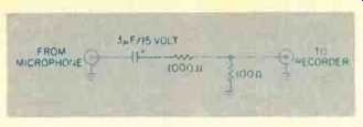
My diagram below shows the 20 dB attenuator with a 50 Hz roll-off achieved by adding a 3 uF/15-V capacitor. Delete the capacitor if the roll-off is not desired. The pad will reduce the d.c. level in that case.
Alan Feierstein; New York, N.Y.

Critic's Reply
Dear Sir:
Please don't change your music critics. I usually find myself in total agreement with their reviews.
Perhaps Mr. Martis should consider why young musicians imitate their heroes so often. Almost any Junior High School musician can, given the resources, duplicate their music, even the aura of Crosby, Stills and Nash. As for the top forty ideals, this person is obviously on the outside looking in.
But he's right in the fact that it takes a lot to be a "superstar"; like perfect teeth, symmetrical ears, or conversely, a readily identifiable costume or 9,000 watts of twelve-bar, three-chord change, heavy metal garbage.
John B. Hamblin; Quartz Hill, Cal.
Burwen System
Dear Sir:
Richard S. Burwen's system (April) has got to be the most fantastic home sound system I've yet seen. Just reading and looking at the article seemed to make my system cringe out of embarrassment--and for some unexplainable reason it just doesn't sound the same anymore.
Just out of curiosity, what is the total dollar value of the whole "thing?" This wasn't mentioned in the article.
C. Engebretsen; Port Reading, N.J.
Editor's Comment: We're sorry that your system doesn't sound the same anymore, and we don't think it's possible to put an accurate dollar value on the Burwen system--let's just say it's expensive.
---------------------
Circuit Revision
Dear Sir:
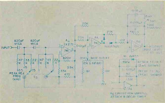
Several readers have called attention to an error in my dynamic noise filter circuit revision (Dear Editor, Sept. 1975). The 470 Ohm and 3.9 K resistors at the output of 4A ill Fig. 6 were omitted. These provide the stated closed-loop gain of 2.7 in 4A; without them it will oscillate. The corrected circuit is shown below.
Some had trouble selecting the FET's required for the circuit of Fig. 8 in the original article. For new construction I recommend an inherently matched dual FET, National Semi conductor type 1410, which should be available at distributors in July at under $2.00 each. Using my samples of this new FET, I have found the following value changes desirable in the circuit of Fig. 8: R4 = 20 K, R5 = 4.7 K, C1 =.047 µF and C2=.015 µF.
This filter is under consideration for marketing as a single-channel kit. It effectively boosts the S/N of acoustic records, 78s and tapes by at least 8 dB.
I shall be glad to send complete literature, when available, to anyone interested.
Maxwell G. Strange
11710 Wayneridge Ct.
Fulton, Md. 20759

(adapted from Audio magazine)
= = = =