MANUFACTURER'S SPECIFICATIONS
Power Output: Stereo, 200 watts per channel into 1, 2, 4, or 8 ohms, 20 Hz to 20 kHz; Mono, 400 watts into 0.5, 1.0, 2.0, or 4 ohms, 20 Hz to 20 kHz.
THD: 0.1 percent maximum from 0.25 W to rated output.
IM Distortion: 0.1 percent maximum, any combination of frequencies from 20 Hz to 20 kHz up to instantaneous peak power of 400 W stereo, or 800 W mono.
Frequency Response @ 1 watt: 20 Hz to 20 kHz +0, -0.25 dB; 10 Hz to 100 kHz, +0, -3 dB.
Hum and Noise: 95 dB below rated output.
Damping Factor: Stereo, 16 @ 1 ohm, 50 @ 2 ohms, 30 @ 4 ohms, 16 © 8 ohms; Mono, 16 @ 0.5 ohms, 50 @ 1 ohm, 30 @ 2 ohms, 16 @ 4 ohms.
Input Impedance: 100,000 ohms.
Input Sensitivity: 0.75 V or 2.5 V, level adjustable.
General Specifications:
Power Requirements: 120 V 50/60 Hz, 70 to 550 watts.
Front Panel Dimensions: 16 3/16 in. (41 cm) W x 7-1/8 in. (18 cm) H.
Chassis Dimensions: 15 in. (38.1 cm) W x 141 in. (36.8 cm) D, including connectors; 1 1/8 in. (3.8 cm) clearance required in front of panel for knobs.
Weight: 85 lbs. (38.5 kg).
Price: $1199.00.
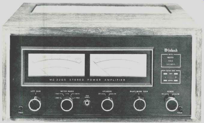
It isn't often that McIntosh Laboratory Inc. introduces a completely new line of power amplifiers, but when they do, the news is generally greeted with a fair amount of excitement from dyed-in-the-wool audiophiles as well as loyal "Mac" fans. The MC -2205, pictured here, is one of a new generation of high-performance power amplifiers introduced recently, and we have now had an opportunity to put it through its paces, to listen to it, and to examine its construction and design philosophy. Detailed examination of the front panel on this impressive looking anodized gold and black panel tells us much (though by no means all) about some of the new features incorporated in this amp.
Dominantly featured are a pair of large, illuminated power meters one for each channel. Calibrated in watts as well as in decibels, the meters can be set to operate in several different modes. When the meter switch is set to watts, one uses the upper scale, which is calibrated to beyond 200 watts (the rated output of each channel of the amplifier when it is used in the stereo mode). When the 0 dB, -10 dB or -20 dB scales are selected, the meters read in decibels, relative to a 0 dB = 200 watts reference, while in the Hold position of the switch the meter once more indicates watts and locks to the highest power peak delivered during playing. If signals are removed while the meters are set to the Hold position, the meter pointers will slowly decay (at a rate of about 10 dB per minute). Lighted words to the right of the meter area indicate which meter mode has been selected. Below these illuminated words is another area containing four indicator lights a pair of green lights for "normal" and red indicators for "limit." The limit lights are also associated with McIntosh's new Power Guard circuit about which we shall have much more to say presently. In addition to the meter range switch, the front panel also contains left and right/mono gain controls (when used as a mono amplifier, only the right channel input is active on the rear panel), a speaker Off/On switch (which can be set to Off to permit private headphone listening via the adjacent phone jack provided) and an a.c. power On/Off switch.
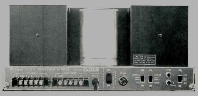
The rear panel is equipped with barrier -strip speaker terminal blocks for left and right speaker connection. Since the McIntosh MC -2205 employs output transformers, a variety of impedance taps are available (1, 2, 4 or 8 ohms for stereo connection, 0.5, 1.0, 2.0 and 4.0 ohms for mono use) and, of course, full rated power is available regardless of the impedance chosen an advantage inherent in the use of matching output transformers. An unswitched convenience a.c. receptacle is located adjacent to the line fuse-holder, near which are the Power Guard switch (ordinarily set to the Normal or "On" position) and a mono/stereo switch. Left and right input jacks come next, and next to them is the input sensitivity switch which selects 0.75 or 2.5 volt sensitivity for rated output.
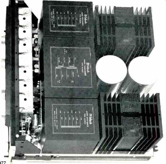
Construction and Circuit Features As can be seen from the chassis view of the MC -2205, the amplifier is as ruggedly constructed as most McIntosh products. The unusual weight (85 lbs.) of the amplifier is, in part, due to the use of those famous McIntosh auto -transformers.
While some may argue that the interjection of autoformers in the output circuitry of a solid-state amplifier poses performance problems, McIntosh stoutly maintains that the use of such transformers offers more advantages than disadvantages. While we will certainly not get involved in that old argument (the proof is, after all, in the listening), we should point out that, indeed, transformers used at the low impedance levels required by solid-state output devices behave quite differently from "old fashioned" step-down output transformers which were required to translate high -impedance tube output circuits to the low -impedance levels required by loudspeaker loads.
A block diagram of the MC -2205 is reproduced in Fig. 1.
Each input amplifier is a two -transistor feedback amp with unity gain. At the input to each power amplifier section is a monolithic differential transistor. Input and feedback signals are applied to this amp. The second stage is a class-A voltage amplifier with applied feedback. The pre-driver, driver, and output sections are fully complementary.
The output stage consists of six complementary power transistors connected in a single -ended push-pull parallel arrangement. The bias network for the output stage is temperature compensated, assuring class -B operation at any temperature or power level. Output transistors are mounted on large, black anodized aluminum heat sinks. The output of the amplifier is switched by a heavy-duty relay to the output auto -transformers. The relay is driven by a transistor switch and also provides transient -free turn -on and turn-off. Relay turn -on takes place approximately two seconds after power is applied to the amplifier. A short turn-off time constant opens the relay's contacts when power is turned off before the main power supply voltage drops. A patented "Sentry Monitoring" circuit monitors output signals. At signal levels up to rated output, this circuit has a high impedance and does not affect the output. However, if the power outputs exceed design maximum, the circuit limits signals to the output transistors. Both the positive and negative halves of the output signal are monitored independently.
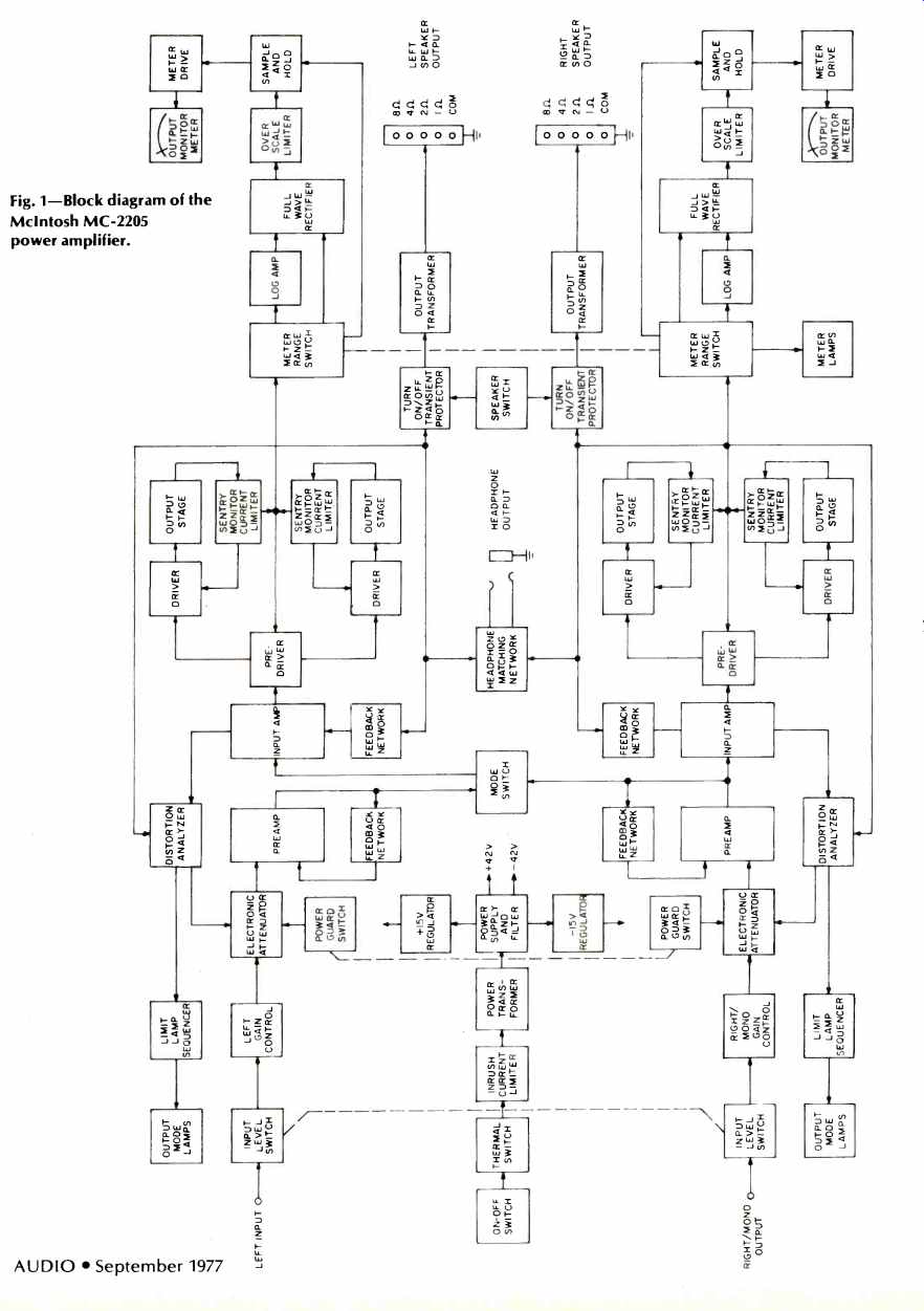
Fig. 1-Block diagram of the McIntosh MC -2205 power amplifier.
Limit Indicator and Power Guard Circuits
The MC -2205 has a waveform comparator circuit which compares output and input waveforms. If waveform differences reach 0.5 percent, the red Limit indicator on the front panel illuminates while a distortion content of 1.0 percent causes the Power Guard circuit to act. Differences in waveform are first converted to a control voltage which is applied differentially to a high gain op -amp where it is amplified 100 times and detected by a full -wave bridge rectifier and applied to a Schmidt trigger programmed to sequence the front panel indicators. The same control voltage actuates the Power Guard system by operating a light emitting diode/light dependent resistor network. The LDR is part of an attenuator between the volume control and the input amplifier. Both the Limit indicator and Power Guard circuits are operated separately for each channel.
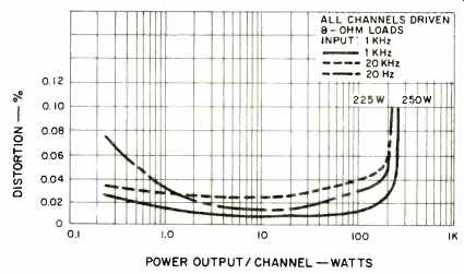
Fig. 2-Harmonic distortion characteristics.
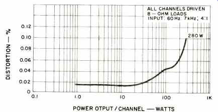
Fig. 3-Intermodulation distortion characteristics.
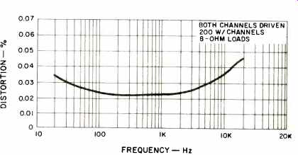
Fig. 4-Distortion vs. frequency.
Laboratory Measurements
The graphs of Fig. 2 show harmonic distortion as a function of power output for the MC-2205 at three frequencies, 1 kHz, 20 Hz, and 20 kHz. Nominal rated harmonic distortion (0.1 percent) was reached at an output level of 250 watts per channel at 1 kHz and approximately 225 watts per channel at the two frequency extremes. (Note that the vertical axis of this graph has been greatly expanded to better illustrate the low levels of distortion measured.) McIntosh's traditionally conservative ratings are such that this amplifier might well have been "FTC rated" at 225 watts per channel in stereo. Full rated power (200 watts per channel) is, in fact, obtainable with no more than 0.1 percent total harmonic distortion from 17 Hz to 34 kHz, beyond the 20 Hz to 20 kHz limits stated by the manufacturer.
Intermodulation distortion is plotted as a function of power output in Fig. 3, using the standard SMPTE frequencies of 60 Hz and 7,000 Hz in a 4:1 ratio. Rated IM distortion (0.1 percent) was reached at an output level of 280 watts per channel with both channels driven. (Note: our wattage measurements are "equivalent watts." Translated to McIntosh's "peak wattage" specification statement, output would have been in excess of 500 watts per channel, rather than the 400 watts claimed in their published specifications!) Residual noise and hum measured 100 dB below full rated output, while damping factors corresponded almost exactly to those stated for the various impedance connections. In case you are wondering why the damping factors vary the way they do, depending upon auto -transformer output taps connected to the load, bear in mind that the "looking back" impedance used in calculating damping factor includes the impedance of that portion of the auto -transformer winding which is in series with the output stage take-off point. Thus, the highest damping factor is observed at the 2-ohm tap, since that tap is closest to the input tap to the transformer, to which the output stages are connected. Although the 8-ohm damping factor may seem low (16) compared to some of the astronomical damping factor figures quoted for solid-state amplifiers that do not employ output transformers, we could not attribute any sound quality deficiencies in our subsequent listening tests to this factor. Distortion vs. frequency at rated output is plotted in Fig. 4 and reached a maximum of 0.045 percent at 20 kHz.
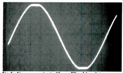
Fig. 5-Sine wave output with amplifier driven into clipping with Power Guard "Off."
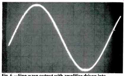
Fig. 6.-Sine wave output with amplifier driven into clipping with the Power
Guard "On."
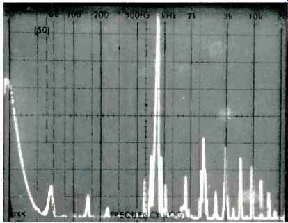
Fig. 7-Distortion components with the Power Guard "Off."
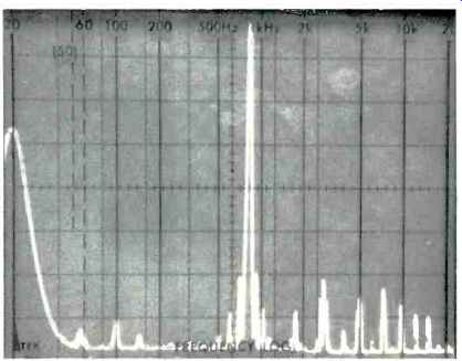
Fig. 8.-Distortion components with the Power Guard "On."
Tests of The Power Guard Feature
One of the most intriguing aspects of this new amplifier from McIntosh is the novel Power Guard circuit which has already been described. In order to test its effectiveness, we applied a 1 kHz test signal to the amplifier, increasing its amplitude until obvious output clipping was taking place with the Power Guard switch turned off. The resulting output waveform is displayed in the 'scope photo of Fig. 5. With the identical signal applied, we flipped the switch to Normal, and observed a significant diminution in output signal clipping, as illustrated in Fig. 6. With the same overdriving signal applied to the amplifier, we analyzed signal output by means of our spectrum analyzer. With Power Guard off, higher level harmonics (third and fifth) were approximately 44 and 48 dB below the reference 1 kHz spike as shown in the scope photo of Fig. 7. A second analysis of the output signal was made after the Power Guard switch was once again set to Normal and, this time, the third harmonic contribution was instantly reduced to some 57 dB below rated output reference, while the fifth harmonic distortion component was reduced to some 63 dB below rated output (see Fig. 8). Impressive as these results are, we recognized, of course, that people don't generally listen to continuous sine-waves and were curious to find out what the Power Guard circuit could do when subjected to more complex signals.

Fig. 9--Clipped complex waveform with the Power Guard "Off."
Fig. 10-Output signal of Fig. 9 as reproduced with the Power Guard "On."
Accordingly, we next applied an IM test signal to the amplifier, driving it well beyond clipping, as shown in Fig. 9.
Turning on the Power Guard circuit once more, the waveform was instantly restored to an almost totally undistorted shape, as illustrated in the 'scope photo of Fig. 10. In fact, we discovered that the Power Guard circuit is fast enough to diminish the amplitude of even a single cycle of a 20,000 Hz tone burst. Further, the Power Guard circuit is able to reduce or attenuate input signals to as little as one-tenth their actual amplitudes, if necessary, in order to maintain low distortion in the event of inadvertent excessive input signals.
Use and Listening Tests
A full evaluation of the McIntosh MC -2205 amplifier really involves more than just musical listening tests. Certainly, this amplifier delivers clean, tight sound with an absence of any audible coloration. Its power reserve is more than enough to handle even the most inefficient of loudspeaker systems.
With so much available power, one has to be careful when selecting speakers to be used with this amplifier. But, given speakers that can handle all that power, one has a sense of security about this amp since the auto -transformers, in addition to the other built in protection circuits, protect speakers from damage in the unlikely event of an amplifier circuit failure. Should a direct current component appear at the output, it would be shunted by the auto -transformers and would not damage the speakers.
The so-called "price/performance" ratio of a high-quality stereo amplifier is not a simple thing to define. Certainly, on a dollars-per-watt basis, the MC2205 is quite costly.
But how does one measure McIntosh's enviable reputation for long-lived components? How can one set a value upon the many military grade components used in the construction of this amp, or upon McIntosh's unequivocal guarantee (printed right above the published specifications) that every single unit sold will either meet or exceed those published specs or your money back? We have been told that most McIntosh product owners are extremely loyal customers and that few base that loyalty upon price alone. Having lived with and listened to the cool -running, conservatively rated, good sounding Mac MC-2205, we believe we can understand that loyalty.
-Leonard Feldman
(adapted from Audio magazine, Sept. 1977)
Also see:
McIntosh MX-117 Tuner-Preamp (Jun. 1982)
= = = =