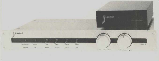
Manufacturer's Specifications
Frequency Response: 1 Hz to 4 MHz, +0.-1 db.
Maximum Output: 8 V.
THD: 0.01%.
IHF IM Distortion: 0.01%.
Phono Input Sensitivity: 0.15 mV for 0.5 V output at 1 kHz.
Phono Input Overload: 150 mV.
S/N Ratio: 95 dB, IHF A-weighted, for 5-mV signal at MM input.
High-Level Sensitivity: 100 mV.
Phono Input Impedance: 47 kilohms, 100 pF.
Weight: 24 lbs. (11 kg).
Price: $1,985.00.
Company Address: Box 4475, Mountain View, Cal. 94042.
My first experience with a Spectral preamp was in about 1978 at a hi-fi store in Woodland Hills, California. I was impressed with three things: It sounded good, it had a good signal-to-noise ratio with moving-coil cartridges without a step-up device, and it had an unusual circuit topology in that the extra gain needed for MC cartridges was in the output amplifier rather than in the phono stage. I tried to get a unit for evaluation at that time but for various reasons, didn't succeed.
Now, some five years later, I get to play with one for my first profile as a returning reviewer for this magazine. [Editor's Note: I'm extremely pleased about this. -E.P.] First of all, I'm really impressed with the appearance and construction of this preamp. It is one of the nicest pieces of audio gear I've seen, especially its main circuit board. Parts quality, soldering, and general level of construction are first class. Not apparent in the pictures is that the rear panel and main circuit board slide out the back of the chassis as a unit upon removal of four screws in the rear panel. This makes for easy repair and update.
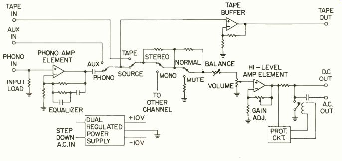
Fig. 1--Block diagram and gain structure.
Front-panel controls include, from left to right, four two position toggle switches and two rotary controls for volume and balance. The first switch selects phono or one auxiliary input, the second is a tape/source monitor, the third is for mono/stereo, and the fourth is a 20-dB mute. Also on the front panel are two LED indicators, for power on and to indicate the action of the output amplifier protection circuit.
A separate power supply provides two separate a.c. feeds for the preamp proper. It incorporates a large power transformer, a three-prong a.c. socket, a 115-230 V a.c. selector switch, the main power-line fuse, a 5-pin XLR connector, and a display which shows the logo and the model number when the power supply is plugged in.
Circuit Description
A block diagram of the DMC-10 is shown in Fig 1. The circuitry consists of five major circuit blocks-a phono equalizer stage, a tape-out buffer, a high-level amplifier, high-level amp protection circuit, and the power supply. Not shown in this diagram are attenuators in the tape-in and AUX signal paths before signal selection. The gain of the phono circuit is a fixed 40 dB. Total gain of the output section, including mode switch, volume and balance loss when phono is selected, is about 34 dB with the internal adjustable gain pots at maximum. This gives sufficient over all gain, 74 dB, for moving-coil use. With the adjustable output-amplifier gain pots at minimum, output gain is reduced about 23 dB for an overall phono gain of 40 + 11 or 51 dB. AUX and tape inputs go through attenuators, with the result that gain from AUX or tape to main output varies from -1.4 to + 22 dB over the range of the output gain pots. To complete the picture of this unusual gain structure, the tape-output buffers have +12 dB gain, so that AUX to tape-out gain is 0 dB. When phono is selected, gain to tape out is 52 dB. Since the tape-out buffers are run off the same supply voltages as the phono preamp, the input of the tape-output buffer will clip before the phono preamp's does. This gain in the tape buffers was probably included to get sufficient tape recorder feed levels with low-output moving-coil cartridges.
The possibility exists that the tape-out buffers could clip when using a high-output moving-magnet pickup on strong record modulations. More about this under the measurements section.
The actual circuit is shown in Fig. 2. As can be seen, the two main amplifier blocks have similar circuitry. A dual monolithic N-channel FET forms an input differential amplifier, the sources being fed from constant-current diodes, and a potentiometer to adjust output d.c. level to zero volts. This FET stage is direct-coupled to a differential PNP-transistor second stage whose load is an NPN-transistor current mirror. The net effect of the composite second stage is to provide gain and to convert the sum of the differential signal to a single-ended signal with respect to ground at the collectors of the right-hand PNP and NPN transistors. A variable bias rheostat allows a d.c. spread to bias the gates of the output devices, which are MOS-FET transistors connected as source followers. Two P-channel MOS-FETS are used in parallel to more nearly match the characteristics of the one N-channel MOS-FET.
Negative feedback is taken around the phono preamp in the form of an RC network that provides RIAA equalization.
Non-frequency-selective negative feedback is applied to the output amplifier, the series arm of which is variable to control overall closed-loop gain. Idling current in the MOS FET output stages is about 20 mA in order to adequately drive their loads, which is as low as 100 ohms for the output amp.
The output of the phono preamp is coupled to the selector switch through a 10-p,F polypropylene and polystyrene parallel combination from Wonder Cap. Output from the output amplifier is either direct-coupled or through a 10-uF capacitor, depending 'moon which output jacks are used. The input coupling to the phono circuit is through a small ferrite-core choke to attenuate r.f. interference. A phono loading socket, with a switch that provides four selected resistors down to 10 ohms, allows for good flexibility of input termination.
The power supply for the DMC-10 is unusual in that half-wave rectification is used to develop the unregulated plus and minus d.c. voltages which are about ±28 volts. Ripple of the unregulated voltages shouldn't be a problem as each supply has 4,000 uF of filter capacitance for a total of 16,000 uF! This is in the range of power-amplifier filter capacitance. Separate rectifiers, filter capacitors, and regulators are used for each channel. The regulators are integrated-circuit, three-terminal devices that provide ± 18 V for all the circuitry except for the transistors which power the mute relay and the indicators in the protection circuitry, which operate on unregulated +28 V.
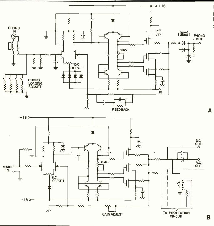
Fig. 2--Schematics of phono preamp (A) and high-level amp (B) sections.
The protection circuitry consists of a quad comparator for each channel and a two-transistor arrangement to drive the mute relay and front-panel indicator. The comparator circuits are sensitive to two properties of the output signals from the output amplifiers: The integrated d.c. value, with a time constant of one second, and the energy present above the audio range. If either or both of these quantities reach protection thresholds, the final stage of the comparator circuit goes negative, which operates the mute relay and changes the color of the protection indicator LED from green to red. All of this protection is in the interests of protecting one's power amplifier and speakers.
Measurements
Circuit gains and IHF sensitivities were measured first.
IHF sensitivity is that input signal which produces 0.5 V out of the main preamp output for the related input function, with volume control at maximum (see Table I). Phono noise with "A" weighting was measured for various bandwidths and source impedances. IHF noise specifications call for an input signal of 5 mV at 1 kHz for moving-magnet inputs and 500 ILV for moving-coil inputs. The source or terminating impedance for noise measurements for moving-magnet in puts is an RLC network composed of a 500-mH inductor in series with 1 kilohm, this series network in parallel with 125 pF of capacitance. This simulates a typical moving-magnet cartridge fairly well. Source impedance for moving coil is to be 100 ohms. Since the phono stage of the DMC-10 can be used for either, measurements are done for both conditions.
Further, the procedure specifies that the unit's volume control be set to produce 0.5 V output in order to simulate typical conditions of use. Noise as referred to the input is shown in Table II. The IHF signal-to-noise ratio of the phono input as a moving-magnet preamp is 5,000 µV to 0.48 µV, or 80.4 dB. As a moving-coil preamp, it's 500 µV to 0.12 µV, or 72.0 dB. If one considers the phono signal-to-noise ratio by reference to the older 10 mV at 1 kHz, 20 Hz to 20 kHz bandwidth, and shorted input, the result is 93 dB. Clearly, the DMC-10 is a quiet preamp when used with moving magnets. As a moving-coil input it is satisfactorily quiet, but paralleled bipolar devices in other preamps have yielded input noise levels that are some 10 to 15 dB quieter.
Phono equalization error for a resistive source is shown in Fig. 3. Input impedance of the phono stage over a band width of 20-20 kHz is equivalent to 44 kilohms in parallel with 270 pF.
Phono total harmonic distortion was under 0.01% from 20-20 kHz at levels below clipping. CCIF two-tone distortion with equal-amplitude 10-kHz and 11-kHz signals yielded a first-order difference 1-kHz signal of less than 0.01% up to clipping. SMPTE-IM distortion was also less than 0.01% up to clipping.
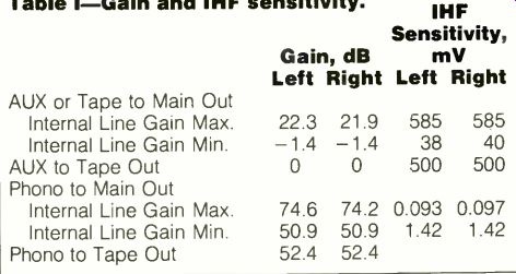
Table I--Gain and IHF sensitivity.
Phono overload versus frequency was measured at the output of the phono circuit and at tape-out. The results appear in Table III. Several things are apparent here. One is that the phono preamp clips at a lower output voltage than the tape-out buffer. When referenced to tape out, the 1 kHz input level for overload is rather low, but in respect to overloading the phono output, it is acceptably high at 80 mV. The phono circuit is not affected by the tape buffer clipping, so when listening through the whole circuit phono input acceptance is okay. If one wants to avoid tape-buffer clipping when recording, it would be wise to seek lower output moving-magnet pickups.
Scope photos of pre-equalized square waves are shown in Fig. 4. Figure 5 shows one very good property of this phono circuit. If a 10-kHz pre-equalized square wave is increased in level until clipping is reached at tape output, the waveform stays symmetrical. Many, if not most, preamps begin to develop asymmetries in such a signal well below clipping.
Phono channel-to-channel crosstalk was measured on a pre-equalized basis. Both channels were essentially the same. The crosstalk for a square wave was in phase. For sine waves, crosstalk was -100 dB from 20 to 500 Hz, rising to -93 dB at 1 kHz, -83 dB at 5 kHz, -71.4 dB at 20 kHz and-66 dB at 50 kHz. This is excellent, indeed.
An unusual feature of the output amplifier in the DMC-10 is that its high-frequency bandwidth is essentially constant over the full range of the volume control and variable output amplifier gain. The manufacturer's specs for a rise time of 20 uS are rather optimistic. In order to observe a square-wave output of more than about 200 mV P-P, it was necessary to disable the protection circuitry. It was found that the circuit had about 0,5113 rise and fall times for any position of the volume control and internal gain controls at any level up to clipping. Extraordinary! This corresponds to a high-frequency bandwidth of about 700 kHz. Low-frequency response of the output amp extends flat to d.c. at the direct-coupled output jacks. Using the d.c.-coupled outputs, the-3 dB frequency naturally depends on the load, being 1.6 Hz for a 10-kilohm load, 0.32 Hz for 50 kilohms, and 0.16 Hz for 100 kilohms. These are calculated responses for the 10 uF output coupling capacitors.
Square-wave responses for the output amp are shown in Fig. 6 for 20 Hz and 20 kHz and an IHF load of 10 kilohms in parallel with 1,000 pF. The tilted 20-Hz trace is for the a.c. coupled outputs.
IHF signal-to-noise ratio for the AUX or tape input is measured with a 500 mV input signal with the volume control adjusted for 500 mV out of the preamp. Noise is measured with "A" weighting and an input termination of 1 kilohm, with internal gain at maximum, the signal-to-noise ratios were-84.0 and -78.2 dB for left and right channels.
With internal gain at minimum,-102.3 and-100.3 dB were obtained. The reason for the difference in signal-to-noise ratio for the two extremes of output amplifier gain is that at minimum gain the volume control is at or near maximum and

Fig. 3--RIAA equalization error (note expanded scale).
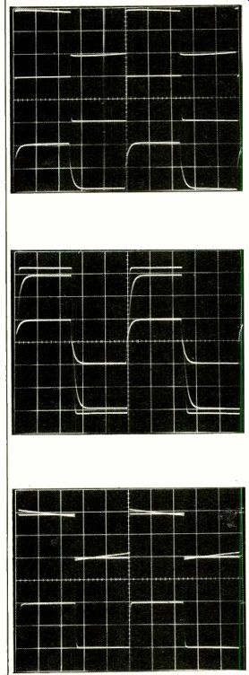
Fig. 4--Phono response to pre-equalized square waves: (top) 40 Hz, 5 mS/ cm;
(middle) 1 kHz, 200 µS/cm; (bottom) 10 kHz, 20 RS/cm.
Fig. 5 Large-signal square-wave phono response; 10-kHz pre-equalized square wave, measured at tape output. (Scales: Horizontal, 20 µS/cm; vertical, 5 V/cm).
Fig. 6 Response of output amplifiers with IHF standard load to 20-Hz, top, and 20-kHz, square waves. Top is with a.c. and d.c. coupling, 10 mS/cm. Bottom is 10 µS/cm; both 1 V/cm.
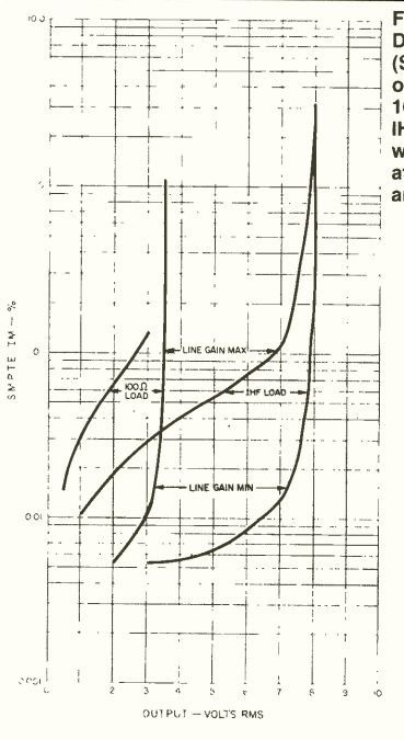
Fig. 7--Distortion (SMPTE-IM) vs. output for 100-ohm and IHF loads, with line
gain at minimum and maximum.
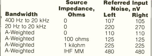
Table II--Noise, referred to input.
maximum signal gets into the input stage in respect to its referred input noise. Crosstalk between channels for the output section was measured, with an input termination of 1 kilohm. The crosstalk for square-wave signals was in phase.
Results were essentially the same for both channels; -91.5 dB (noise) at 20 Hz, rising to -73.4 dB at 500 Hz, -67.5 dB at 1 kHz, -47.5 dB at 10 kHz, -41.6 dB at 20 kHz, and -33.1 dB at 50 kHz.
Input impedance for AUX or tape inputs was 13.4 kilohms, and output impedance was about 100 ohms.
Spectral rates the DMC-10 at 1 V output into a 100-ohm load, with THD or IM distortion of less than 0.01% from 20 Hz to 20 kHz. With a 100-ohm load, one has to use the d.c. coupled outputs or suffer a low-frequency-3 dB point of 160 Hz at the a.c.-coupled outputs. For a 100-ohm load at 1 V output, THD was less than 0.01% from 20 Hz to 20 kHz.
Clipping occurred at 4.5 V rms, with the plus half-cycle flattening first. The preceding was at maximum internal output gain. With an IHF load, THD was about 0.015% at 5 V rms output, with clipping at 9.5 V rms. With IHF load and minimum output amp gain, THD was less than 0.01% up to clipping, from 20 Hz to 20 kHz. SMPTE IM distortion versus output, load, and minimum and maximum output amp gain is shown in Fig. 7. The higher of the two channels is plotted.
Use and Listening Tests
Equipment used for evaluating the DMC-10 consisted of an Infinity Air Bearing turntable with either a Grado Signature IV moving-magnet cartridge or a Koetsu EMC-1B "Black" moving coil, Marantz Model 9 or Sumo Gold Power amplifiers, Infinity RS-II speakers, and Stax SR-X/Mk. 3 headphones.
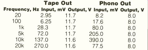
Table III--Phono overload vs. frequency.
First listening was with the Grado cartridge. Reproduction was open and detailed, with good imaging. Bass was ex tended and tight, midrange and highs were well defined without high-frequency edge or irritation. Spectral balance and harmonic structure was similar to a developmental reference tube preamp used for comparison, though replication of space and "air" about instruments was not as good as with the tube preamp. With the Koetsu pickup, circuit gain was more than adequate, as was subjective signal-to-noise ratio. Sound with the Koetsu was even more open and detailed, and I found myself really getting into and enjoying music and forgetting reviewing. I would have to say this preamp is one of the few solid-state preamps that I like.
In summary, the DMC-10 is a very high-quality, well-made unit that should appeal to the serious audiophile and music lover. I would recommend that potential preamp buyers give it a serious listen.
-Bascom H. King
(Source: Audio magazine, Sept. 1983)
Also see:
Spectro-Acoustics Model 217 Preamplifier (Equip. Profile, Feb. 1978)
Soundcraftsmen Pro-Control Four Preamplifier (Feb. 1988)
= = = =