Manufacturer's Specifications:
System Type: Sealed-box woofer, electrostatic midrange/tweeter.
Drivers: 12-in. cone woofer, 23 1/2 in. x 47 1/2 in. electrostatic panel.
Crossover: 125 Hz, active.
Frequency Range: 28 Hz to 24 kHz, ±2 dB.
Sensitivity: 90 dB SPL at 1 meter for 2.83 V.
Impedance: Woofer, 4 ohms nominal, 3.5 ohms minimum; midrange/tweeter, 6 ohms nominal, 1.4 ohms minimum at 24 kHz.
Power Handling: 200 watts continuous.
Dimensions: Speakers, 26 3/4 in. W x 74 in. H x 12 in. D (68 cm x 188 cm x 30.5 cm); electronic crossover, 17 in. W x 2 in. H x 10 in. D (43.2 cm x 5.1 cm x 25.4 cm).
Weight: Speakers, 120 lbs. (54.4 kg) each; crossover, 12 lbs. (5.4 kg).
Price: $7,000 per pair; passive-crossover version, Monolith IIIp, $6,500 per pair.
Company Address: 2001 Delaware St., Lawrence, Kans. 66044.
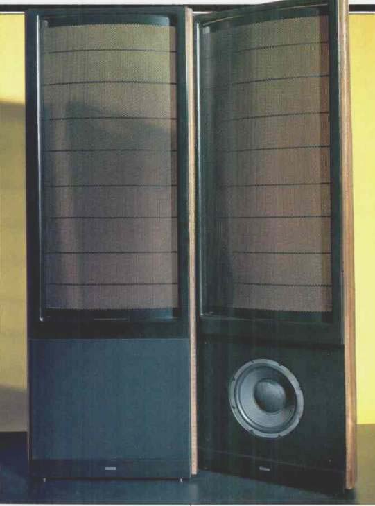
The Martin-Logan Monolith IIIx is a fantasy of high-end extremes. Striking in appearance and size, and outrageously expensive, it is one of the best-sounding speaker systems made. One's eyes scan a room and stop at the two monoliths standing out from the wall. Contrasting textures, rounded shapes, and refined finishes frame the naked functionality of the curved electrostatic panels. As you move towards the speakers, reflections and patterns of holes move in response. You realize that you are looking through the metal-film-metal sandwich that is the speaker mechanism.
You feel compelled to first gently touch them and then to listen to these speakers.
The hybrid dynamic/electrostatic Monolith was the first product of Martin-Logan, a company formed in 1982 by two gentlemen with the middle names of Martin and Logan. Gayle Martin Sanders, who survives as president and chief visionary, explained the development cycle to me. The Monolith was followed by the CLS, an exercise to explore the limits of the full-range electrostatic concept. It is currently produced and is considered by many to be the finest speaker made, even given its lack of output at very low frequencies. Next was a downsized and more affordable follow-up to the Monolith, appropriately named the Sequel.
This speaker has received high critical acclaim in its price range and has been a commercial success. Next came the Statement, an all-out, 2,000-lb., electrostatic/dynamic hybrid for $55,000 ($60,000 with a balanced crossover) exploring the limits of cost-no-object design.
With this development work behind them, Martin-Logan took a fresh look at the Monolith. Sanders slimmed and refined the appearance and the company developed an electronic crossover and new woofer driver. Many small improvements were imported from the other designs. A passive crossover of new design is also available for those who prefer to use a single amplifier. I recommend biamping. This is the use of a low-level or electronic crossover to divide the frequency range for separate woofer and tweeter amplifiers. These two amplifiers per channel connect to the woofer and tweeter directly. The amplifiers need not be identical. A stereo amp of the appropriate type may be used for the woofer of each channel and a different model stereo amp may be used for the tweeter of each channel. The advantages are the elimination of distortions produced or allowed by the high-power passive filter components normally used between amplifier and driver.
Also, the electronic filters can be more complex, to better compensate for known drive-unit, cabinet, and room irregularities.
If you insist on using an extremely expensive stereo amplifier, but you can't afford two as required for a biamplified system, I suggest that you use the golden amp on the electrostatic tweeters, which receive everything above 125 Hz. A mid-priced, mid-powered amp will work perfectly with the conventional 12-inch dynamic woofers below 125 Hz.
The extra $500 for the active crossover plus an extra $500 or so for a capable woofer amplifier is well worth it.
Dynamic woofers are commonly used for bass in electrostatic speaker systems. One might think that electrostatic force fails to work at low frequencies, but this is not the case. It, and the magnetic force of a dynamic speaker, can each produce a steady continuous force equivalent to 0 Hz.
Stepping back from practical considerations, physics would imply that the electrostatic speaker is nearly ideal for all frequencies because its diaphragm has almost no structural requirements and so can be made nearly as light as the air into which it delivers acoustic energy. This produces an inherently high efficiency, low distortion, and unlimited bandwidth.
Back to reality and long wavelengths: An electrostatic panel (or the cone of a dynamic drive unit) cannot radiate acoustic power unless something separates the outputs from its front and rear, which are of opposite polarity. For wavelengths that are smaller than the panel or cone, there is no problem. The sound is beamed forward and backward pretty much independently. For long wavelengths, however, the panel size will not direct the radiation, and cancellation will occur. The solutions are to make the surface larger or to seal off the rear radiation with a box. Since the wavelength of a 30-Hz tone is about 37 feet, we look at the box solution.
Containing the rear radiation of a diaphragm produces a pressure that must be overcome for the front to radiate. With the materials we have available on this planet, the dynamic drive unit is a far more suitable high-pressure device. It is the need for a box that causes practical electrostatic speakers to be inefficient for deep bass.
Other practical considerations keep electrostats from performing up to the theoretical ideal. The thin film diaphragm must have a high resistivity and be positioned midway between the two stationary, perforated conducting plates.
This means the film must be stretched slightly and clamped at its edges. Now, we have a resonant panel with a less than ideal "ballooning" motion that produces waves travelling across its surface. This results in some radiation pattern and frequency response irregularities. Also, to interface with conventional amplifiers, an audio transformer is required to bring the high impedance of the electrostatic panel down to a normal range. This transformer will have winding resistance, interwinding capacitance, and magnetic nonlinearities to some degree. In the end, it is designer finesse, not operating principle, that is responsible for producing a superb speaker system.
The Monolith Ill's 2-foot x 4-foot panels poised above the woofer box are the bare essence of 'stat. There are only four basic parts: Two perforated steel stators insulated by a vinyl coating, spacers, and the mylar diaphragm-all visible and unobstructed. The panels are curved to control horizontal directivity and segmented into horizontal strips by spacers to force the diaphragm to follow the curve of the stators. The stator-diaphragm sandwich is held in a rounded plastic frame, which in turn is fixed between slim wood uprights running the entire 6-foot height of the system. The woofer box is gloved in a stitched leather-texture cover except for the front, which is covered by a snap-on grille frame and sheer fabric.
A detachable IEC power cord is used for the 3000-volt polarizing voltage power supply for each speaker. There is no power switch because the current required to maintain charge is extremely low; in fact, the speakers will play for half an hour after being unplugged. You have a choice of using flat or spiced adjustable feet to level the speakers.
Audio connections for the woofer and midrange/tweeter section are made to multi-way terminals on standard 3/4-inch double-banana spacing. The crossover is external, allowing owners of the passively-connected Monolith IIIp to upgrade to the electronic crossover of the IIIx. For this reason, I performed some of my tests with both the passive and active crossovers.
The electronic crossover for the IIIx is built to the highest quality standards for audio equipment. Audio connectors are gold-plated RCAs. Inside, discrete-component amplifiers are used and other components are close-tolerance types. This is particularly important for the frequency-determining components. Front-panel controls include rotary switches for "Frequency" (30 to 50 Hz, in 5-Hz increments) and "Boost/Cut" (- 4 to +4 dB, in 2-dB steps). A pair of internal DIP switches, accessed through cutouts in the rear panel, alter the gain of the low-pass channel from-6 to +6 dB, in 18 steps, to compensate for any differences in gain between the user's amplifiers. As with the speaker, there is no on/off switch, but heat and power consumption are low. The line is detachable via an IEC socket.
The Monolith II system is available in a variety of fine woods and finishes. It can be customized by the factory and is even available with the electrostatic panels covered by a fabric "sock."
Measurements
Some creativity was required to measure these speakers properly. The basic problem is that the speakers are so large that the standard measurement distance of one meter is proportionately too close to predict response at a greater distance. Technically, it would be in the "near field." How: ever, even at 3 meters (almost 10 feet), a listener is also in the near field. In addition, the speaker radiates equally to the front and rear. Truly anechoic measurements give you only half the sound that fills a room. In the following measurements, I attempted to relate to in-use conditions while maintaining a reference to Audio's standard practices.
Equipment that I use includes the Techron TEF 10 analyzer, Brüel & Kjaer 4007 microphones, and many custom designed circuits and fixtures. In addition, I am now using a Tektronix 2630 Fourier analyzer for impedance and distortion measurements. This two-channel instrument is based on digital signal processing (DSP) chips and a host DOS computer.
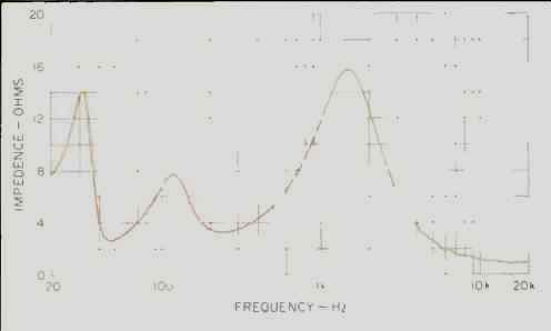
Fig. 1--Magnitude of impedance, using passive crossover.
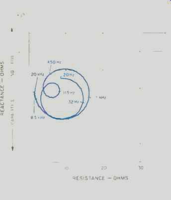
Fig. 2--Complex impedance with passive crossover, showing resistance and reactance
vs. frequency.
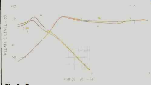
Fig. 3--Frequency response of passive crossover. Note the deliberate underlap
of drive signal around the crossover frequency.
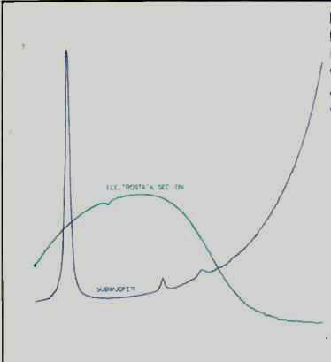
Fig. 4--Magnitude of impedance with woofer and tweeter driven directly.
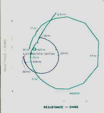
Fig. 5--Complex impedance of woofer and tweeter driven directly.
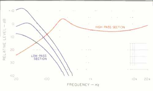
Fig. 6--Frequency response of electronic crossover. Woofer-section responses
are, top to bottom: Maximum setting ("+4 dB") of front panel "BoosVCut" control
(+6 dB bass gain, and "Frequency" dial at 30 Hz) best setting for
my room (0 dB gain, "Frequency" dial at 40 Hz, and 0 dB "BoosVCut" setting),
and minimum setting (-6 dB bass gain, "Frequency dial at 30 Hz, and "BoosVCut" at "-4
4 dB").
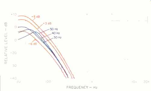
Fig. 7--Frequency response of electronic crossover with-3 dB bass gain for
all three "Frequency" control positions, and for three additional
bass gain settings with "Frequency" at 30 Hz.
Starting with the passive crossover option, Fig. 1 plots input-impedance magnitude of the system. Figure 2 plots the same information in polar form, showing the capacitive and inductive effects with which the amplifier must deal.
This could be considered a typical 4-ohm rated speaker were it not for the drop to 1 ohm above 10 kHz. You may not need full power or lowest distortion in this range, but make sure that the amp manufacturer says that the amp is "safe" with a 1-ohm load.
Figure 3 shows the passive crossover's output to woofer and tweeter with some of its useful response-trimming options. Note the reduced amplitudes at the 125-Hz crossover frequency. Did Martin-Logan blow it here? I don't think so! The same underlap is found in the active crossover, proving that Martin-Logan deliberately did this to provide a seamless blend from woofer to tweeter in the listening room, as we'll see shortly.
With the active crossover and biamp option, the amps must drive the woofer and tweeter input impedances directly. The magnitude of these impedances is shown in Fig. 4 and the reactance and resistance are shown in Fig. 5. The woofer load is normal for a sealed-box design but the tweeter presents the same nasty high-frequency load as it did with the passive crossover.
Figure 6 plots the amplitude response of the active crossover. This is the signal presented to the woofer and the tweeter amplifiers. The extremes of the response options for the woofer drive are shown along with the one found most suitable for my listening room and used in testing. The system's low-frequency response can be matched to the room by the "Frequency" selector switch. The three frequencies are plotted in Fig. 7. This option can help cope with peaks and dips caused by room modes. Low-frequency gain and attenuation are variable via eight computer style DIP switches accessed from the rear of the crossover. Their effect is also shown in Fig. 7.
Anechoic frequency response was measured with the speaker lying on its side in a large parking lot at a distance of 2 meters with 0.2 V input to the crossover. This voltage produces an average of about 4 watts into the speakers.
Remember, with the response shaping in the crossover, the true power varies with frequency. Sound Pressure Level (SPL) was mathematically normalized to the standard 1 meter, 1-watt equivalent. Several tests confirmed that this strange configuration produced a good representation of the first arriving sound heard by the listener. Figure 8 plots the amplitude response, which shows a rather wide variation. Keep in mind that this speaker is a dipole radiator above 125 Hz and is designed to perform in a room. With the active crossover circuitry, any response shape would be possible. This has to be what Martin-Logan wanted.
The phase shift associated with the amplitude response of Fig. 8 is plotted in Fig. 9. The normal high-pass response of the woofer produces the low-frequency phase lead. The crossover at 125 Hz produces a lag of 360°, which affects the range from below 100 Hz to nearly 1 kHz. Above that, the electrostatic panel shows essentially no additional phase shift. This amount is common in many speakers.
Moving into the listening room, the 3-meter response, including early reflections, is one of the most uniform I have seen. It is actually flatter than the anechoic response. This is plotted in Fig. 10 for on axis and 30° off axis.
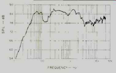
Fig. 8--On-axis anechoic frequency response at 1 meter, referenced to an input
of 0.1 V into the electronic crossover. This input results in approximately
2.0 V (1.0 W into 4 ohms) into the speakers from amplifiers of 26 dB gain.
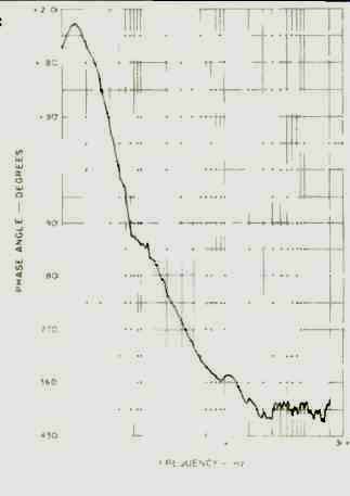
Fig. 9--On-axis anechoic phase response using electronic crossover.
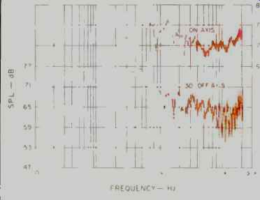
Fig. 10--Three-meter room response measured on axis and 30° off axis.
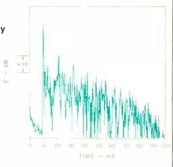
Fig. 11--Energy-time curve of one speaker in listening room for energy centered
at 2 kHz. Scale for on-axis curve is at right. The off-axis curve has been
lowered for clarity.
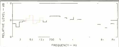
Fig. 12--Third-octave average frequency response of two Monolith IIIx speakers
in listening room setup.
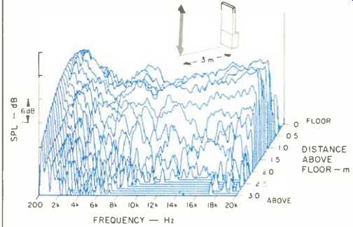
Fig. 13--Vertical off-axis frequency response, taken along a straight vertical
line from ground to 3.1 meters up, 3 meters from speaker.
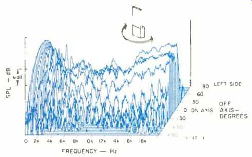
Fig. 14--Horizontal off axis frequency response, taken from one side, around
front, to the other side of speaker.
When I use instruments to set up a speaker system, I try for minimization of early reflections and a high density of delayed reflections in the midrange. This is best accomplished through room geometry, speaker placement, and speaker directivity control, not by gross application of sound-absorbing foam. Dipoles like the Monolith are my preference for directivity control. Figure 11 shows why. This in-room energy-time curve plots energy around 2 kHz received by the microphone at the listening position as a function of time. We see a strong first arrival at 10 mS and a suppression of any significant reflections for another 10 mS, followed by the desired onset of dense reflections dying out steadily as dictated by room reverberation time.
This room time response is characteristic of that sought in a live end/dead end room design. Frequently however, unknowledgeable "deadening" of the walls around the speakers does not achieve it. Here, we achieve it with a free-standing speaker near a live corner, with only a sound diffusing reflector behind it. Part of the secret is in the dipole radiation pattern, which avoids side-wall reflections. Another part is the combination of woofer at floor level and a limited vertical "beam" of mid and high frequencies that eliminates the floor-bounce problem. Either a sizable distance to the rear wall or a diffusing reflector, as I used, is required to delay the rear sound.
Figure 12 is another non-standard room plot. This one is frequency response of the Monolith pair averaged over third-octave bands and over several positions in the centerline listening area. Note that there is no "hole" at 125 Hz as one might have expected from the anechoic response. Also, bass response is increased and extended and the upper range is smoothed and falls with the desired slope. Normally, Audio does not include data that are specific to one listening room, but I wanted to show that there is a reason for the Monolith's non-flat anechoic response.
Back to the anechoic environment: Fig. 13 plots the vertical off-axis response. Since the usual listening distance is in the "near field" of these speakers as far as vertical directivity is concerned, a measurement method that represents this was used. Instead of plotting the "launch angle," the response variation with height above the floor at a 3-meter listening distance is plotted. The range of height plotted is from floor level to a height of 3.1 meters. The "beam" of acceptable response extends from just below 1 meter to just below 2 meters. This accommodates seated and standing listeners while avoiding early floor and ceiling reflections.
Horizontal directivity is plotted through 180° from one side, around the front, to the other side in Fig. 14. Note the fall-off of energy to the sides. This is due to the dipole radiation and, as noted earlier, it prevents early reflections from side walls if the speakers are rotated properly. There is an approximately 30° angle of acceptably flat response.
When a speaker exhibits a fairly consistent response off axis over a wide frequency range, as the Monolith does, it is called "constant-directivity." Constant directivity, which is possible only with quite large speakers, ensures that the reverberant sound matches the direct and early sound.
Figures 15, 16, and 17 show the fundamentals and harmonics of the musical test tones E1 (41.2 Hz), A2 (110 Hz), and A4 (440 Hz), respectively, for input powers up to 100 watts. These plots were made with the Tektronix 2630 Fourier Analyzer and look somewhat different from the previous plots made with the TEF. First, they include the fundamental as the series of 31 uniform peaks on the left. Second, harmonics out to at least the eighth are plotted. Third, the "floor" is limited to 0.1%, which is an extremely small amount of distortion. The Monolith has moderate distortion at 40 Hz at high levels and exceptionally low distortion above that.
Modulation of A4 (440 Hz) by E1 (41.2 Hz), mixed in a one-to-one ratio is shown in the "3-D" plot of Fig. 18 for the frequency range covering 50 Hz on either side of the 440 Hz test tone. Modulation by the 41.2-Hz tone will produce undesired new tones 41.2 Hz on either side of 440 Hz. Input gain to the analyzer was adjusted for each power level applied to the speaker, to maintain a constant level to the analyzer. This is seen as the constant level of 440 Hz in the center. The modulation sidebands just rise out of the 0.1% measurement floor at high levels. This extremely low distortion is due to the separation of the test tones by the crossover. Additional tests, not shown, were run with both tones in the electrostatic panel's range, and IM distortion was still extremely low.
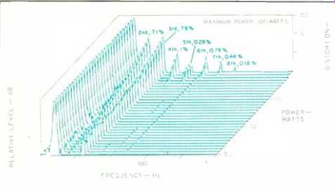
Fig. 15-Harmonic distortion products for the musical tone E1 (41.2 Hz).
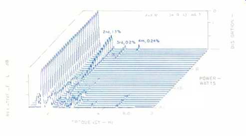
Fig. 16-Harmonic distortion products for the musical tone A2 (110 Hz).
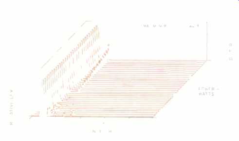
Fig. 17-Harmonic distortion products for the musical tone A4 (440 Hz).
Power linearity over the entire frequency range is plotted in Fig. 19. The curve shows the power input and frequency at which the acoustic output fails by 1 dB to respond in a linear manner. Woofer distortion limits output in the range from 20 to 80 Hz. A mechanism unknown to me limits the electrostat between 200 Hz and 10 kHz, and my power amp protected itself from the 1-ohm load above 10 kHz. I would recommend 100 watts per channel for the woofer and a robust 200 watts per channel for the tweeter.
Figure 20 is the Monolith's time response at 1 meter with an analysis of energy centered around 10 kHz. The initial peak is quite sharp, considering that the tweeter is physically spread out over 8 square feet. Energy at a reduced level is radiated for several more mS. This could be the arrivals from panel segments which are off axis, diffraction from the frame, or traveling waves in the diaphragm.
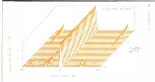
Fig. 18--IM distortion on 440 Hz (A4) produced by 41.2 Hz (E1) when mixed
in one-to-one proportion.
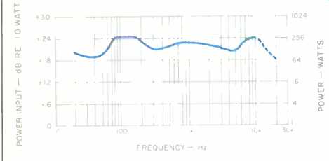
Fig. 19--Power linearity.
Input power handling (approximation based on 0.1 V into electronic crossover) versus frequency for 1-dB compression of the output.
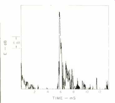
Fig. 20--One-meter on-axis energy-time response.
Use and Listening Tests
I first set up the Monolith in my home listening room, which is approximately 18 feet x 25 feet with an 8-foot ceiling. For aesthetic reasons, I placed the speakers less than 3 feet from the wall behind them and angled them in slightly. The sound bothered me until I installed an equalizer and reduced amplitude in the range from 200 to 500 Hz.
Still, it didn't sound quite right; vocals lacked presence.
Before I could find time to experiment with repositioning, I purchased a large rear-projection TV. This was installed between the Monolith speakers and forced me to move back other furniture. I was now able to pull the speakers out more than 4 feet from the wall behind them. Whether it was the increased distance or the large object between them I don't know, but the sound was dramatically improved. The equalization was no longer needed and the absence of presence was, well, absent.
In addition to stereo music, I used the Monolith in conjunction with four dynamic speakers in a video surround sound system. The source was a digital LaserDisc player feeding a Sony TA-E1000-ESD DSP preamp in surround mode. Despite the sonic mismatch between the dynamic speaker in the center and Monolith speakers on the left and right, the effect was quite good. Much of the center information is dialogue and the music is mainly left and right so it worked out. Occasionally, when an effect, such as a passing car, would pan from left to center to right, the difference in tonality was somewhat distracting.
I mention this use because I believe that a top-quality audio system can co-exist with a surround-sound video system. The best of the LaserDiscs have CD-quality digital sound. I find it most enjoyable to view an orchestra or related scene while listening. In addition to surround-encoded films, I listened to and watched the following Laser Discs: Antonin Dvorák, Symphony No. 9, Vaclav Neumann, Pioneer MC036-22LD; New Year's Eve Concert 1987, Herbert Von Karajan and Vienna Philharmonic, Sony SLV4598J; The Six Brandenburg Concertos, J.S. Bach, Nikolaus Harnoncourt and the Concentus Musicus, London 071 204-1; Jimi Live at Monterey, Jimi Hendrix, HBO Video ID6573HB. Next, I moved the speakers to my lab and its adjacent listening room, which measures 18 x 27 x 10 feet. This room has variable acoustic panels, and I elected to make the area behind the speakers reflective but with diffusion for the rear sound radiation. I placed the Monolith pair about 6 feet out from an 18-foot wall, about 8 feet apart and angled inward about 20°. Angling was somewhat critical for high frequency balance and maximizing acceptable listening area, but as it happened, the first position tried just worked.
At the listening location, about 10 feet away, the Monoliths sounded much like other high-quality speakers, especially dipoles like the Magnepan and Quad ESL. Image height was a bit high, but it was easy to get used to. Overall timbre was a bit on the dark or rich side, with extended, clean bass. There is no criticism implied here, just an observation such as one might make about a tine concert hall. High frequency sounds were never forward or obvious, but neither was the sound dull. I discovered that I could pick out and follow single instruments in a complex orchestration with uncanny ease.
Imaging on the stereo centerline was very accurate and uniform across the soundstage. Centered, forward vocals could have been a little more tightly focused. Likewise, distant pickup, such as the bass and conga of "Tinden bara Gar," Opus 3, Test Record 1, CD 7900, could have been rendered with more stage depth. However, on the really difficult stuff with orchestra, organ, and choir, like Andrew Lloyd Weber's Requiem (EMI CDC 7 47146 2), the Monolith came through with the chilling sense of space, texture, and power contained in this music.
Hosting a local Audio Engineering Society meeting presented an interesting opportunity to test the Monoliths. An old friend of mine, Don Fostle, is writing a book on the Steinway piano company and wanted to compare the sounds of four brands of concert grand pianos. I agreed to provide a sound system and blind comparison of the four piano recordings he had. The professionally made recordings were of the same artist performing the same music in the same hall on the same day. Only the brand of factory tweaked piano changed.
There were 15 AES members crowded into my listening room to judge the recordings. The Monoliths had no trouble reproducing the full volume of a concert grand. Despite some difficulty in covering the entire listening area with upper-mid and high frequencies, there were numerous comments regarding the remarkable clarity, detail, and openness.
These speakers will play very loudly even though they never sound like they are blasting. Uncompressed recordings of percussion can cause temporary ringing in the ears if you are careless with the volume control. Ultimate woofer output will not satisfy bass freaks, but it is adequate if no bass boost is used.
The Monolith woofer deserves special comment. At first viewing, this ordinary looking 12-in. woofer in a sealed box would seem to be a mediocre solution, at best, to the electrostat's problem with low bass frequencies. Not so.
This woofer integrates flawlessly with the dipole upper range, thanks to its low distortion and the finessing of the crossover slopes. No buzzes or distortion were heard on music. When overdriven, it simply stopped getting louder in a graceful manner. This is a better speaker than many so-called subwoofers on the market.
If you get the impression that I am mightily impressed with the Monolith, you are right. Is it the best that I have heard? It is a contender for the honors, but I would have to make that judgment from a side-by-side comparison of speaker/room systems. The Monolith demands space. From my experience, they must be placed well out from the wall behind them and used in a room not much smaller than 18 x 25 feet. If you are an avid audio enthusiast with the space and the money, you must hear these speakers.
-David L. Clark
(Source: Audio magazine, Sept. 1991)
Also see:
Martin-Logan SL3 Speaker (Auricle; Jan. 1996)
Electrostatic Speakers: Theory and Practice -- Part 1 (Mar. 1989)
= = = =