Manufacturer's Specifications:
Frequency Response: 20 Hz to 20 kHz, +0,-0.15 dB.
THD: 0.06%.
S/N: 95 dB, A-Weighted.
Input Sensitivity: 60 mV.
Voltage Gain: 18.8 dB at full volume.
Maximum Output Voltage: 8 V rms.
Input Impedance: 10 kilohms.
Output Impedance: 47 ohms.
Dimensions: 17 in. W x 3 1/2 in. H x 8 in. D (43.2 cm x 8.9 cm x 20.3 cm); 19-in. (48.3-cm) front panel optional.
Weight: 15 lbs. (6.8 kg).
Price: $595; 19-in. panel, $100.
Company Address: Mondial Designs, Two Elm St., Ardsley, N.Y. 10502.
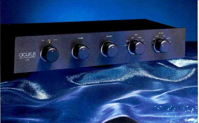
The Acurus L10 is one of a number of products manufactured by Mondial Designs Ltd. under the Acurus brand name. Other products in this line include the A250 stereo power amplifier and the P10 MM/MC phono amplifier.
The L10 is a minimalist design, to improve the odds on maintaining signal integrity. Functionally, the unit has a high level signal selector with a balance and volume control and a line-output amplifier. Additionally, a tape-output selector permits recording a source different from that selected for listening. Like the dual selector systems on many other preamps, however, this one allows the user to accidentally interconnect the output and input of a tape deck or external processor by selecting the deck or processor as both the listening and recording source. The feedback resulting from this could damage one's speakers and even one's ears. The manual does at least warn of this possibility, saying that the design was done this way to avoid putting another switch contact into the signal path.
The L10 features six signal inputs, plus dual outputs to simplify biamping; connectors are gold plated. The output amplifier uses discrete, matched transistors. Metalized poly propylene capacitors are used in the signal path, and resistors are 1% metal-film types. The volume and balance controls are custom designed, with die-cast cases and large swept areas for low contact resistance. The unit also has dual-mono d.c. supplies with separate, discrete regulation for both the positive and negative rails of each channel.
Five rotary controls grace the front panel, all equally spaced, which create a very attractive overall look. From left to right, the controls are: "Off/On/Mute," "Volume," "Balance," and the "Listen" and "Record" signal selectors. On the rear panel are the signal input and output connectors and the a.c. line cord.
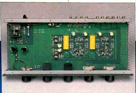
The large p.c. board that takes up the entire interior of the L10 is a study in beauty and simplicity of layout. The power supply (to the left, as seen from the front of the unit) takes up about 20% of the board, 60% more is taken up by the discrete output-amplifier circuitry and power-supply regulators, and the 20% between the output and power supply is empty. All front-panel controls are mounted to the p.c. board. All in all, a very neat and tidy unit, with excellent components and construction.
Circuit Description
The six inputs are all routed to the two selector switches. The "Record" selector feeds the two tape output jacks through individual buffer resistors. The "Listen" selector feeds through the balance control into the volume control, which in turn feeds the line amplifier through two resistors in series. The muting switch works by shorting the junction of these resistors to ground, in both the "Off" and "Mute" positions. The preamplifier is designed to be powered all the time, and the "Off" position does not actually turn its power off.
The input stage of the line amp is composed of a complementary differential amplifier using bipolar transistors. There is some emitter feedback, and emitter-supply current is through resistors instead of active current sources. The input stage is directly coupled into the second stage, a complementary circuit of common-emitter amplifiers that also uses bipolar transistors. The collectors are tied together and direct-coupled to the output stage, which consists of large-junction FETs connected as source followers. Overall negative feedback is taken from here back to the inverting input of the input differential amplifier. Signal output is coupled through a 10-uF film capacitor and individual, small-value buffering resistors to the two output jacks. This basic circuit topology is fairly common in solid-state power amplifiers, and I have seen it used in some preamps as well.
The power supply consists of a full-wave capacitor-input plus and minus supply. Resultant filtered d.c. voltage is regulated down to the working supplies of ± 18 V by zener regulators feeding emitter-follower pass transistors. There is an individual pass transistor for the positive and negative supplies to both channels.
Measurements
Gain and input sensitivities as a function of output loading are presented in Table I. No surprises here except for the relatively high loss into the IHF load at the tape output jacks, due to the 2.5-kilohm value of series buffer resistors used.
Frequency response at the main output jacks with the volume control at maximum and balance centered, is shown in Fig. 1 for instrument, IHF, and 600 1-ohm loads. With the volume control set at the-6 dB point, which usually rolls off the highs more, the response was substantially the same in the measurement bandwidth shown. With the 600-ohm load, low-frequency response is rolled off due to the value of the film output-coupling capacitor.
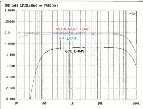
Fig. 1--Frequency response.
Table I--Gain and Sensitivity, all inputs.
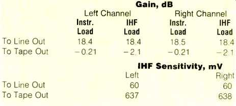
Table II--Noise levels vs. bandwidth. The IHF S/N ratios were 92 dBA for either channel, with 500-mV input signal and volume control set for 0-dB gain.

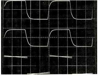
Fig. 2--Square-wave response, for 100 kHz into IHF load at full volume (top)
and with volume about 6 dB down (middle), and for 20 Hz with both instrument
and IHF loads (bottom). Scales: Vertical, 5 V/div.; horizontal, 2µS/div.
for 100 kHz, 10 mS/div. for 20 Hz.
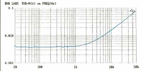
Fig. 3-THD + N vs. frequency, for 10 V output into IHF load.
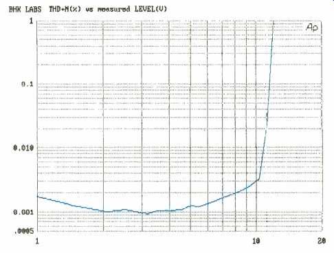
Fig. 4-THD + N vs. output voltage into IHF load, at 1 kHz.
Table II-Noise levels vs. bandwidth. The IHF S/N ratios were 92 dBA for either channel, with 500-mV input signal and volume control set for 0-dB gain.

Square-wave response is illustrated in Fig. 2, and it's first rate. The top and middle traces are for a frequency of 100 kHz. In the top trace, with the volume control at maximum and an output level of 10 V peak to peak, the beginning of slewing is apparent. Rise- and fall-times are about 0.8 uS here. Taking off the IHF load doesn't materially change the waveform. Driving the output to a higher level yielded a slew rate of about 30V/RS. In the middle trace, the volume was set at about-6 dB and the input level was increased to again produce about 10 V peak to peak. Rise- and fall-times have' increased to about 1µS. Low-frequency tilt for instrument and IHF loading is shown in the bottom trace for a frequency of 20 Hz. Square-wave performance of the L10 is excellent indeed.
Total harmonic distortion plus noise versus frequency at an output level of 10 V rms into the IHF load is shown in Fig. 3. The measurement bandwidth used here was 500 kHz, to best illustrate the way distortion increases with frequency.
The steady reading of approximately 0.4% at frequencies below 1 kHz is mostly out-of-band circuit noise. Figure 4 shows how THD + N at 1 kHz increases with output voltage into the IHF load. Here, measurement bandwidth is 22 kHz, to portray distortion more accurately. Distortion at realistic working levels is vanishingly low.
Referred input noise for various bandwidths, and IHF signal-to-noise ratios, are enumerated in Table II. Noise is low enough to be inaudible in most situations.
The volume controls tracked within 1 dB down to levels of -70 dB. This is reasonable for a control that Acurus calls an undetented stepped attenuator and is presumably executed with film technology instead of with discrete resistors.
Interchannel crosstalk was measured with the undriven input terminated in 1 kilohm. With the volume at full rotation, crosstalk was at least -90 dB or better at frequencies up to about 1 kHz, and then increased at 6 dB per octave to reach -60 dB at about 35 kHz. With the volume turned halfway down, which reduces this preamp's gain by 20 dB, crosstalk was about -85 dB up to 1 kHz, again increasing at 6 dB per octave to about -60 dB at 35 kHz. These results were just about the same for either right-to-left and left-to-right crosstalk.
Output resistance measured a low 48 ohms for both channels. Input impedance depended on the volume control setting; it was lowest at about 9.8 kilohms with the volume full up and increased to about 12 kilohms with the control at mid position. The overall input-to-output phase is noninverting.
Use and Listening Tests
Signal sources used to evaluate the Acurus L10 line-level preamplifier included an Oracle turntable fitted with a Well Tempered Arm and Spectral Select MCR pickup, a Krell MD-1 CD transport used with VTL Reference and VTL Straight Line converters, a Nakamichi 250 cassette recorder, a Technics 1500 open-reel recorder, and a Nakamichi ST-7 tuner. Vinyl records were played using a step-up tube phono preamp fed into one of the inputs of the L10. (This circuit can drive the L10's 10-kilohm inputs pretty well, as far as distortion and low-frequency response are concerned.) Other preamps on hand during the review period included a Quicksilver and a First Sound Reference II passive unit.
Power amps used included an experimental, 50-watt/channel switching amp designed by a friend of mine, prototype Quicksilver 135-watt mono tube units, and a pair of Carver Silver Sevens. Speakers used were Win Research SM-10s.
Most of my listening was done with the little switching amp. Overall sound was quite clean and musical with good space and dimension. When things got loud and complex, I noted a bit of congestion in the sound that I didn't hear with the First Sound passive unit. When I paired the L10 with the Crown and Quicksilver amps, the resulting sound wasn't as good as with the switching amplifier, which is unfortunate as this is an experimental amp.
Be all that as it may, when I stop playing Supercritic and bear in mind that the Acurus L10 is less than one-third the price of the other preamps, then I must say that the Acurus performs pretty well. It gave me good musical satisfaction when paired with the right amp, with a clean, musical sound that included good spatial characteristics. "Completely satisfactory" is the opinion that I'm sure many listeners will form when they audition this preamp.
-Bascom H. King
( Audio magazine, Sept. 1992)
Also see:
Acoustic Research Limited Model 2 Preamp (Equip. Profile, Aug. 1994)
Acoustic Research Turntable (July 1984)
Acoustic Research 338 Speaker (Nov. 1995)
Acoustic Research AR98LS Speaker (Equip. Profile, Jan. 1985)
= = = =