MANUFACTURER'S SPECIFICATIONS
Speeds: 15, 7 1/2, and 3 3/4 ips. Reel Size: 7 in. max. Motor: 4-pole hysteresis sync. Frequency Response: 20-32,000 Hz at 15 ips, (30-25,000 Hz ± 3 dB); 20-28,000 Hz at 71/2 ips, (30-23,000 Hz ±3 dB); 20-15,000 Hz at 3 3/4 ips. Wow and Flutter: Below 0.09% at 15 ips; below 0.09% at 71 ips; below 0.13% at 33% ips. Signal-to-Noise Ratio: 53 dB or more. Input Sensitivity: Microphone, 0.3 mV; Phono-1 (ceramic or crystal), 100 mV; Phono-2 (mag), 2 mV; Aux-1, 30 mV; Aux-2, 100 mV. Outputs: (fixed) 1.0 V. (variable) 0 to 1.0 V. Headphone Output: 55 mV across 8 ohms.
Dimensions: 17 in. W., 18 1/2 in. H., 8 1/2 in. D. (upright position).
Weight: 33 lbs.
Price: $ 329.95.
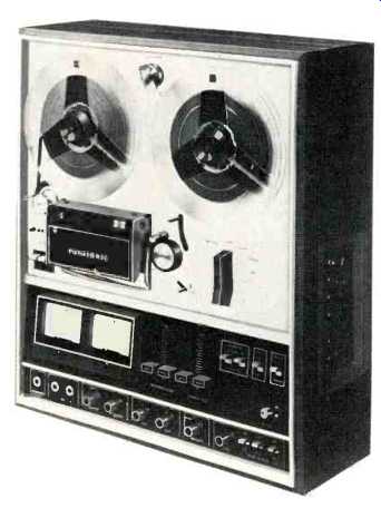
As the average recordist becomes more proficient in his hobby, he is likely to want to try some "professional" assignments in which he plans to end up with some commercially produced phonograph records, and for this purpose, he will want to use a higher speed than is usually available on the average recorder. The Panasonic RS-736US will answer his desires for the higher speed--15 inches per second. At the same time it provides the usual 7 1/2 ips which he will use for his not quite so important work, as well as the economical 3 3/4 ips which he is likely to use for recording the spoken word or possibly for casual programs recorded off the air. And in all these speeds, this machine will give him adequate service, as well as the sort of flexibility he needs for his various activities.
When we speak of flexibility, we are referring to the many uses to which this deck can be put, since it provides a wide range of inputs-two pairs of PHONO inputs, two pairs for AUX (all of which are phono jacks), and two standard phone jacks for MICROPHONE inputs. In addition there are two pairs of phono jacks for outputs-one pair with a fixed output and one variable, and controllable from the front panel with separate slide controls for each channel. Since the machine has three stereo heads, you can monitor while recording from either source or tape so you can determine during the process if you are actually getting anything on the tape, as well as comparing the quality of the two. You can make sound-on sound recordings monophonically, enabling you to create a quartet, for example, from a single performer. You can add echo, record a "language-lab" procedure in which the instructor records on one channel while the student listens to the playback of this channel and then records his own reply on the other. All these facilities are simplified by the provision of separate level controls for most of the inputs. While these level-set controls are ganged to operate on both channels at once, you still have separate recording level controls for each channel. It is a very flexible machine.
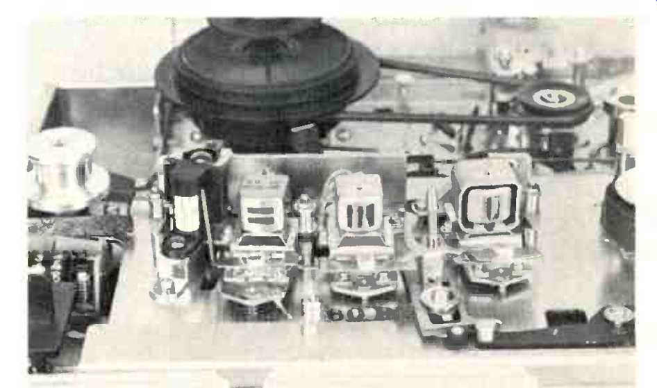
Fig. 1--Close-up of the head assembly. Heads are of hot-pressed ferrite
material for long wear.
Physically, the RS-736US has the usual two reel hubs across the top of the panel, with the speed control knob between them at the very top of the panel. At the left center is the left tension lever around which the tape is passed before passing the guide roller. For ease in threading, the tension level locks its maximum counterclockwise position, giving easy access to the guide roller. The head cover is just to the right of the guide roller, and its upper part covers the wiring to the heads and accommodates the power indicating pilot light. The lower two thirds of the head cover hinges upward to make threading as easy as possible, as well as to give access to the heads for cleaning. The tape next passes the capstan and the large idler roller, thence past the right tension arm and upward to the takeup reel. Underneath the idler or pinch roller is a small lever which serves to disable the retracting mechanism when winding rapidly to cue the sound to aid in locating the desired portion of the tape.
The pinch roller is removable, and to change from 7 1/2 ips to 15, it is replaced with a smaller one, and at the same time the small capstan screw is replaced with a large screw which holds the larger capstan sleeve. Thus the two lower speeds are selected by the knob on the panel, using the small capstan screw and the large pinch roller, while the selector switch remains in the 7 1/2-15 position and the screw and roller are changed for the highest speed. This is a method that has been in use on U.S.-made machines for perhaps 20 years, and it is effective and serviceable. Next to the right is the function lever which controls tape motion.
The lower third of the front panel is given over to the amplifier and its controls. In the upper portion are the two 4-in. meters, flanked by the two recording-level slide controls-one for each channel. Next come the two slide controls for output level-again one for each channel-followed by the two monitor switches which select between SOURCE and OFF-THE-TAPE monitoring--one for each channel. Next is the NFD switch--which actuates the noise-level control that reduces highs during the absence of a sufficiently high level of sound in the output.
This is followed by the tape selector switch, which should be actuated whenever low-noise tape is being used. It serves to decrease high-frequency equalization slightly.
Along the lower section of the panel a number of jacks and controls are located. First there is the three-circuit headphone jack which is fed from a transistor stage through a transformer to feed the usual low-impedance stereo headphones. Next are the two microphone input jacks. The next item is a knob which actuates a switch that selects inputs from MICROPHONE, PHONO 1, and PHONO 2. This is followed by an input level-set control for the selected source of the preceding switch. The next two knobs control, respectively, AUX 1 and AUX 2 input levels.
These controls all operate on both channels with dual controls, but individual channel level control can be handled by separate recording-level controls-one for each channel. The next knob controls the equalization required for the three tape speeds, both for record and playback.
Next is the level control for the specialized functions-sound-on-sound and echo. This is followed by three switches which control these functions-first is the SOUND-ON-SOUND switch, then a switch which selects whether you are recording from right to left or left to right, and finally there is the echo switch with its ON and OFF positions.
The two recording levers are on the upper panel just to the left of the head cover and under the guide roller. In addition, separate indicator lights are illuminated when any of the three specialized function controls are turned from the OFF position.
For aid in locating the actual gaps on the recording, erase, and playback heads, their positions are marked on their shield for easy readability.
On the right side of the cabinet in the lower portion is another panel on which are mounted the two PHONO-1 (ceramic or crystal) input jacks, the two PHONO-2 (magnetic) input jacks, the two pairs of AUX jacks--low level and high level--and the two pairs of OUTPUT jacks-fixed and variable. Then there is a five-terminal DIN receptacle for connection to receivers and amplifiers similarly equipped to provide both record out and playback in connections, a ground terminal, and two convenience outlets-one switched and one unswitched. The power cord also enters at this panel.
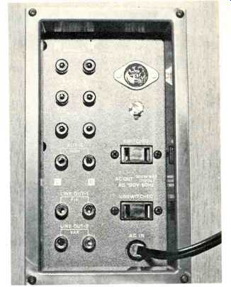
Fig. 2--Connection panel located on the lower right side of the cabinet.
Circuit Description
The unit contains two separate amplifiers for each channel--one for recording and one for playback. The record amplifiers employ six transistors each. The first two provide the pre amplification for microphone and Phono-2 for magnetic pickups, and the required equalization is furnished by feedback around these two transistors in the preamp section. The low-level AUX input connects directly to the input of the following stage, while the high-level Aux-2 input feeds through a resistor to one of the specialty controls.
The remaining four stages serve to provide further amplification, with the last stage being equalized for recording at the three speeds, using resonant circuits across the emitter resistor. The output of this last stage feeds the record head directly, with controllable bias voltage being furnished through a capacitor and a variable resistor.
The playback amplifiers each have seven transistors, with playback equalization for the three speeds around the first two stages, monitoring selection between the preamp section and the next stage. The ensuing three stages provide the necessary gain to feed the output lines, with the remaining two used to drive the headphone amplifier and the metering circuit.
The NFD noise suppressor circuit utilizes two additional transistors to which are fed the outputs of the two playback amplifiers, and then, in turn, furnish a d.c. voltage which causes the high frequency response of the amplifiers to be reduced, thus reducing the apparent noise. One additional transistor serves as a voltage regulator to supply a constant source to the amplifiers, and two more are employed as the bias/erase oscillator. (For a basic schematic of Panasonic's NFD circuit, see Fig. 1 of H.W. Hellyer's article in this issue.)
Performance
We tried out the machine in all its functions and found that it performed just as described. Measurements on all the possibilities would take up more space than is available, so only the most important response curves are shown. As to details, bias/erase frequency was measured at 187 kHz, which is well above average. Most measurements were made at 71 ips, with the exception of the frequency responses at all three speeds. Distortion was found to be 0.4% at 10 dB below indicated zero level, increasing to 0.8% at zero, and rising to 3% at an indicated level of +8 dB. Fast forward and rewind times for 1200 feet of tape were 2 minutes and 40 seconds. Wow checked out at 0.05 per cent at 15 ips, 0.08 at 7 1/2, and 0.11 at 3 3/4; flutter at the three speeds was measured at 0.08, 0.1, and 0.14 respectively. Signal-to-noise ratio was a comfortable 55 dB below the 3% distortion point, and with the NFD noise suppressor in operation the S/N was increased by 6 dB. Fig. 3 shows the response from a standard tape for playback response, along with a comparison of the phono equalization provided in the PHONO-2 position (magnetic pickups) with the standard RIAA curve. Note that they are with ± 2 dB throughout the range.
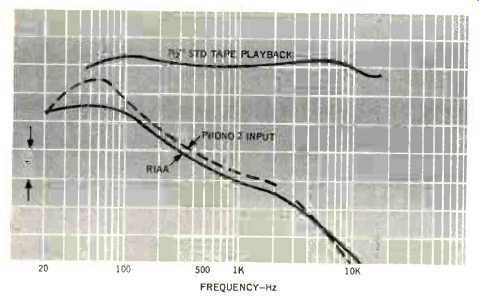
Fig. 3--Comparison between RIAA curve and that of the PHONO-2 input shown
in the lower section. Upper curve is playback from a standard tape at 7 1/2
ips.
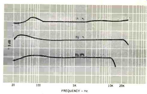
Fig. 4--Frequency response at the three speeds of the machine.
The frequency response curves in Fig. 4 were made from the Bruel & Kjaer sweep record QR-2009, which extends from 20 to 20,000 Hz. The output of a Stanton 681EE cartridge was equalized to within 1 dB of the RIAA curve over the entire range and fed to the Aux-2 input. The output was then recorded on a graphic recorder. For the phono equalization curve of Fig. 3, the cartridge was fed directly into the PHONO 2 input of the Panasonic, and the output similarly recorded.
To sum up, the machine is easy to handle, and with the exception of a slight loosening of the tape tension when the machine is stopped after fast winding, no problems were encountered. It is a handsome machine, and it is certain to provide all the flexibility the average user could imagine.
-C. G. McProud
-----------
(Audio magazine, Oct. 1972)
Also see:
Panasonic Model SA-5800 AM /FM Stereo Receiver (Equip. Profile, Aug. 1972)
Link | = = = =