All About Tape Recorder Equalization
By Herman Burstein
FROM READERS' QUESTIONS and things that appear in the popular audio literature, it seems that tape recorder equalization is less well understood by audiophiles than its importance deserves. The mystery tends to be compounded by the variety of equalization characteristics necessitated by an assortment of tape formulations and tape speeds, as well as by the occasional promulgation or advocacy of new equalization standards.
Therefore the Tape Guide seeks to explain what tape recorder equalization is all about--why it is needed; how it is achieved; how it can be modified to optimize the interdependent requirements of extended treble response, low noise, and low distortion; the nature of the NAB equalization standards, and how equalization is affected by such things as tape speed, tape formulation, use of the Dolby system, etc.
For the most part the discussion assumes that tape speed is 7 1/2 ips. Despite the greatly improved performance obtainable at lower speeds, 7 1/2 ips is the NAB (National Association of Broadcasters) standard speed and is the one generally preferred for high quality home recording. (In fact, some home recordists prefer 15 ips.) In any event, what we have to say applies in principle to all tape speeds.
It is further assumed that the tape machine has: (1) clean and demagnetized heads so that no treble losses occur due to poor tape-to-head contact or magnetization; (2) heads in perfect azimuth alignment (gaps exactly at right angles to tape length) co eliminate treble losses owing to incorrect azimuth; (3) bias set for approximately minimum distortion at mid-frequencies, specifically at 400 Hz.
Why Equalization Is Necessary
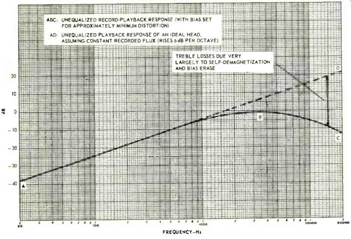
Fig. 1--Unequalized record-playback response of a tape recorder at 7 1/2
ips.
Suppose that the tape machine we have just described has no equalization circuits to alter frequency response, and that it is employed to record and play a tape at 7 1/2 ips.
Further suppose that input signals of constant level are recorded throughout the 20-20,000 Hz range and then played back. A meter connected to the output would typically show the machine's record-playback response to be quite similar to Curve ABC in Fig. 1: Record-playback response climbs steadily at virtually 6 dB per octave (20 dB per decade, to be precise), reaches a peak around 3,500 Hz, and drops substantially thereafter.
Clearly, bass boost is needed to compensate for the drooping bass portion AB, and treble boost is needed to compensate for the drooping treble portion BC. That is the role of equalization-to provide bass and treble boost made necessary by the inherent nature of the tape recording process.
To help us see why Curve ABC is the way it is, Fig. 1 supplies line AD, which is the response of an "ideal" (perfect) playback head if a tape were recorded flat; that is, if the tape contained recorded flux of equal magnitude at all audio frequencies. At this point let us carefully note an important distinction between applying a flat signal to the tape and recording a flat signal on the tape. Losses, which we describe shortly, take place in the treble range of the recorded signal. However, line AD assumes there are no such losses so that a flat signal is recorded on the tape. In sum, AD is the playback response of an ideal head if the tape is recorded flat. AD rises steadily at 6 dB per octave because the head is a velocity device. That is, the head is an electromagnetic generator with a voltage output proportional to the rate of change of the magnetic field of the tape. The field changes at a rate corresponding to the audio frequency. Hence the voltage output of the head is proportional to audio frequency.
For example, at 10,000 Hz the playback head produces twice as much output as at 5,000 Hz, and 10 times as much as at 1,000 Hz. (That is why we say line AD rises 6 dB per octave or 20 dB per decade, since 6 dB represents (very nearly) a doubling of voltage, and 20 dB represents (exactly) a 10-fold increase).
Beyond approximately 800 Hz the record-playback curve fails to continue its 6 dB per octave climb due almost entirely to magnetic losses that occur in recording and become more severe as frequency increases. These losses are of two kinds, self-demagnetization and bias erase, and we shall return to them in a moment. There are also slight losses-especially slight at higher speeds-attributable to the playback head.
Winding capacitance of the playback head may result in treble loss. And there may be some treble loss due to gap width (the wider the gap of the playback head and the slower the tape speed, the greater the loss.) But with a playback head that is well made and boasts a gap as narrow as 40 or 50 microinches, capacitance and gap losses at 7 1/2 ips are usually quite negligible-on the order of 1 dB or less at 20,000 Hz. Thus we are principally concerned with recording losses described by the terms self-demagnetization and bias erase.
Self-demagnetization refers to the fact that the recorded signal on the tape in effect consists of a series of bar magnets end to end. The higher the frequency, the more bar magnets are recorded per inch of tape, so that each magnet is necessarily shorter. But the shorter the bar magnet, the closer together are its north and south poles, and the more their opposing magnetic fields tend to cancel; that is, the signal tends to self-demagnetize. In sum, with increasing frequency the strength of the recorded signal-the amount of magnetic flux on the tape-tends to weaken.
Bias erase is a side-effect of the high frequency signal, typically 75,000 Hz or higher, which is fed in moderate amount to the record head to minimize distortion and generally maximize the amplitude of the recorded signal; this is called bias current. In much greater quantity, about 10 times as much, the oscillator current powers the erase head. Unfortunately, bias current in the record head has the deleterious side effect of also accomplishing erasure-not nearly as effective as the erase head, but erasure nonetheless. Bias erase increases with frequency because the higher frequencies penetrate the tape less deeply and hence are more vulnerable to an erasing field. Altogether, bias current produces treble loss; the larger the bias current (for reduced distortion), the greater the treble loss.
The magnitude of the magnetic losses in recording is indicated by the interval between Line AD and Curve ABC. Recall that AD is the response of an ideal playback head in the absence of recording losses, and that an actual high quality playback head is close to ideal. Therefore the interval between AD and ABC represents recording losses. For example at 15,000 Hz the interval shows a loss of about 30 dB. Roughly 20 dB of this may be ascribed to self-demagnetization and the other 10 dB to bias erase.
Equalization for Flat Response
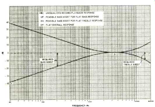
Fig. 2--A feasible pattern of equalization for a tape recorder at 7 1/2
ips.
A major goal of high fidelity is of course flat frequency response, output signals having the same relative levels as the input signals at all audio frequencies. In other words, for constant level input there should be constant level output in the range of approximately 20 to 20,000 Hz. Hence flat response is represented by a straight horizontal line, such as EF in Fig. 2.
Record-playback Curve ABC from Fig. 1 is repeated in Fig. 2, and a feasible scheme of equalization for flat response is straightaway evident. The interval between EB and AB may be interpreted as bass loss, and therefore represents the bass boost needed for flat bass response. Similarly the interval between BF and BC represents the needed treble boost.
Accordingly, GF is a suitable bass equalization curve, rising in a fashion that mirrors the decline AB. And EH is a suitable treble equalization curve, rising in a fashion that mirrors the decline BC. Together, GF and EH complement record playback Curve ABC to produce flat response.
Figure 2 is a workable scheme of equalization and something fairly like it is used. However, matters are not all that simple. In addition to flat response, high fidelity has low noise and low distortion as major goals. For reasons connected with improving the signal-to-noise ratio, actual equalization (the generally employed NAB standard) is a modified version of GF and EH in Fig. 2. But we must postpone, and pave the way for, discussion of NAB equalization in order to deal first with the question of where equalization takes place in a tape machine so as to best serve the triad of goals-flat response, low distortion, and low noise.
Where Equalization Takes Place
We begin with an important observation. Figure 1 shows great treble losses in recording, reaching about 30 dB at 15,000 Hz and 36 dB at 20,000 Hz. Yet Curve EH in Fig. 2 indicates that a treble equalization curve with only 10 dB of boost at 15,000 Hz is needed. The seeming paradox is explained by the fact that treble boost is not required to fully make up for treble losses. Only enough treble boost is needed to achieve flat response. Putting it differently, the rising response of the playback head (the portion of AD above 800 Hz in Fig. 1) compensates for a substantial part of the treble losses. Only the remainder of the treble losses must be made up by Curve EH in order to achieve flat response in the treble range. Thus we note that rising response of the playback head has a key role in treble compensation.
Where should equalization circuits be placed in the tape machine? One might expect that they could be placed in the record amplifier, or in the playback amplifier, or in a combination of the two. However, not just any combination will do, because some offer better results in terms of noise and distortion, while others offer worse.
Without yet explaining anything, one may offer a descriptive general rule: Playback losses are equalized in playback and record losses in recording. Thus Curve GF in Fig. 2 would be supplied by an equalization circuit in the playback amplifier. And curve EH would be supplied by an equalization circuit in the record amplifier.
Why this general rule? If the large amount of needed bass boost were supplied in recording, this would tend to apply excessive signal (magnetic field) to the tape and overload it, resulting in excessive distortion. Alternatively, one would have to greatly lower the recording level, resulting in a poor S/N ratio. Therefore bass boost is applied (largely or altogether) in playback. Moreover, Curve GF in Fig. 2 may be viewed in the guise of a treble cut characteristic. In this vein it serves to reduce noise of the entire tape recording system when used in playback.
Turning to treble boost, we must consider that noise, while prevalent at equal amplitude throughout the audio spectrum, is usually most evident from about 3,000 Hz upward. This is partly because of the human ear's sensitivity in the vicinity of 3,000 to 5,000 Hz. Mainly it is because of the increasing amount of random noise energy as one goes up each octave of the audio spectrum; the more frequencies per octave, the more must be the noise energy. (Clearly there are more frequencies between, say, 3,000 and 6,000 Hz than in the preceding octave of 1,500 to 3,000 Hz.) Thus we characterize tape and amplifier noise as high-pitched (hiss, spitting, frying, etc.) even though low-pitched noise is also present. If treble boost were applied in playback, it would magnify tape noise and noise of the record and playback amplifiers, resulting in a poorer S/N ratio. Therefore treble boost is applied instead (largely or altogether) in recording, where it only magnifies noise of the record amplifier.
A logical and important objection is in order at this point; Won't the treble boost in recording overload the tape (much as a large amount of bass boost might)? The answer would be yes if, for typical sounds, all frequencies had equal peak amplitudes. But for most recorded sounds desired by humans, particularly music, amplitude is usually a good deal less at high frequencies than at mid-range ones, as suggested in Fig. 3. This figure shows for a typical orchestral selection the relative peak levels of audio energy throughout the spectrum.
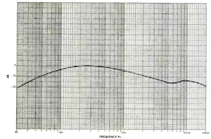
Fig. 3--Smoothed approximation of relative peak amplitudes for a typical
orchestral selection.
Compared with peak amplitude at 400 Hz, there is a drop-off of 15 dB or more at higher frequencies. Therefore, in dealing with the kind of sound generally recorded, a good deal of treble boost is feasible in recording.
This boost is offset by the decline in amplitude of the higher frequencies, which helps prevent the tape from being overloaded. (Another preventative, when necessary, is reduction of recording level by the user.)
A Modified Pattern of Equalization
We have already noted that low noise is one of the three major goals of high fidelity. Put differently, we are interested in high S/N (signal-to-noise ratio). This can be achieved by recording more signal on the tape, especially at high frequencies, where the extra signal can mask the noise.
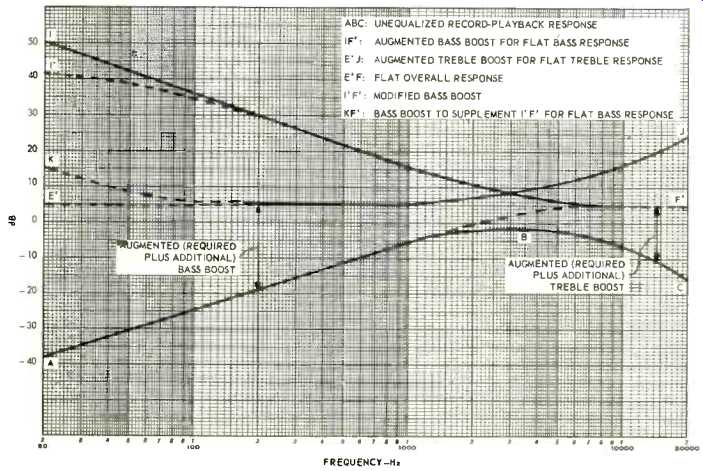
Fig. 4--A modified pattern of equalization to obtain signal-to-noise ratio
(at 7 1/2 ips). improved
Figure 4 shows a modified pattern of equalization that uses additional boost in recording yet results in flat response.
Desired flat response is denoted by Line E'F'. It is 6 dB higher than the corresponding line EF in Fig. 2, reflecting an improvement of 6 dB in S/N ultimately achieved at higher frequencies.
Curve ABC, as before, is the unequalized record-playback response. The interval between AF' and ABC is the treble boost needed to approach flat response at the higher frequencies; that is, response 3 dB below flat at about 3,200 Hz, and increasingly flat as frequency rises. We may refer to this interval as "augmented" treble boost, consisting of the amount originally required in Fig. 2 plus an additional amount for higher S/N. (The interval between BC and the 0 dB line is the originally required treble boost, so that the remainder of the interval between AF' and ABC is the additional boost.) Thus Curve E'J is the augmented treble equalization needed for flat treble response. (E'J is the same distance from E'F' as ABC is from AF'.)
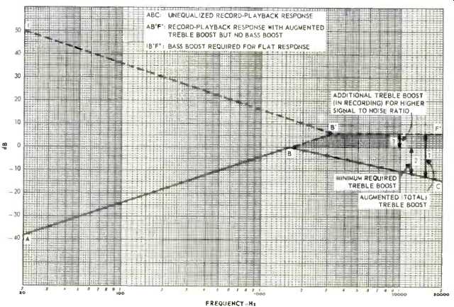
Fig. 4A--Basic scheme of the modified pattern of equalization.
The required bass boost is the interval between flat response E'F' and drooping response AF' (keep in mind that AF' represents the response of an ideal head to a recording made with treble boost E'J). We may refer to this interval as "augmented" bass boost because it consists of the amount originally required in Fig. 2 plus an additional amount.
(The interval between AB and the O dB line is the originally required bass boost, so that the remainder of the interval between AF' and E'F' is the additional bass boost. Thus Curve IF' is the augmented bass equalization needed for flat bass response. IF' is the same distance from E'F' as AF' is from E'F'.)
The story told by Fig. 4 is somewhat complex. It can be made more clear by presenting its essentials in simpler form in Fig. 4-A. (We haven't yet finished with Fig. 4 and shall return to it shortly.) ABC in Fig. 4A represents in linear form the unequalized record-playback response. Line AB'F' shows the record-playback response that would result if there were only augmented treble boost and no bass boost.
Augmented treble boost is depicted by Arrow 1, minimum required treble boost by Arrow 2, and additional treble boost by Arrow 3. Additional boost is further spelled out by the shaded area between BB'F' and BC. Given record-playback response AB'F', it remains to supply bass boost IB'F' in order to achieve overall flat response. AB'F' in Fig. 4-A corresponds to AF' in Fig. 4; and IB'F' in Fig. 4--A corresponds to IF' in Fig. 4.
Returning to Fig. 4, we may ask: Why stop at a 6 dB improvement in S/N at the higher frequencies? Why not add yet more treble boost in recording to achieve still higher S/N. The answer lies in Fig. 3, which shows that, relative to 400 Hz, the higher frequencies are down roughly 15 dB at 15,000 Hz and a bit more at 20,000 Hz. Correspondingly, this allows treble boost of about 15 dB at 15,000 Hz and a bit more at 20,000 Hz without excessive risk of serious tape distortion. Treble boost curve E'J does just about that, with no margin of safety to spare. In other words, in the present state of the art, treble boost in recording which approximates E'J is about as far as one dare go without risking excessive distortion in the upper end of the treble range. (Here lies the reason why some recordists still prefer 15 ips. Treble losses in recording are less than at 7 1/2 ips, so that less treble boost is needed in recording and there is less risk of overloading the tape due to such boost. The recordist speaks of the greater "headroom"-margin between the amount of treble signal applied to the tape and the amount which causes tape saturation-available at 15 ips.) It is difficult in practice for a tape amplifier to fully supply the amount of bass boost indicated by Curve IF' in Fig. 4.
For one thing, an enormous amount of amplification is needed to achieve bass boost which at 20 Hz is up 44 dB from the reference line E'F' and still rising. High amplification is costly, may unduly magnify hum frequencies, and entails the risk of oscillation owing to phase shift or stray feedback. Therefore a preferred course is to allow bass boost to level off, as shown by I'F' in Fig. 4. Now bass boost is up about 35.5 dB at 20 Hz and soon reaches a maximum of 36 dB below 20 Hz.
To compensate for the leveling off of bass boost in playback, some bass boost may be introduced in recording, as shown be Curve KF' in Fig. 4. However, this isn't always necessary, because at low frequencies the playback head often tends to exhibit a slight rise in response owing to what is called the contour effect. Low frequencies correspond to long wavelengths (bar magnets) on the tape. In the presence of long wavelengths, the entire playback head, not only its gap, tends to react to the magnetic flux of the tape. The resultant rise in bass response may approximate KF' well enough to obviate the need for bass boost in the record amplifier.
If bass boost is supplied in recording because the contour effect is minimal, ordinarily this raises no problem of overloading the tape. Figure 3 shows that the typical decline of peak amplitudes at low frequencies would easily offset the bass boost of Curve KF'. A final and key note on Fig. 4: Comparing this with Fig. 2, we observe that an equalization pattern which calls for increased treble boost in turn requires greater bass boost.
Conversely, a decrease in treble boost is accompanied by a decrease in required bass boost. In sum: A given recording characteristic implies a complementary playback characteristic; or a given playback characteristic implies a complementary recording characteristic.
NAB Standard Equalization
The approach of Fig. 4 is followed by the NAB standards for tape recorder equalization. In fact, I'F' is the NAB playback equalization characteristic for 71/2 ips (and for 15 ips as well). For greater clarity, I'F' is repeated in Fig. 5. We underscore the word "characteristic" because the NAB standard does not merely describe the frequency response of an equalization circuit in the playback amplifier (as is the case for RIAA phono playback equalization and for FM tuner equalization). True, measured frequency response of the tape playback amplifier is ordinarily quite close to Curve I'F', but it is not necessarily the same as I'F' in order to achieve flat response. The NAB playback characteristic in Fig. 5 is the sum of playback equalization provided by the tape amplifier plus irregularities in frequency response of the playback head. As already discussed, these irregularities tend to consist of some boost in the low bass region and a slight drop-off in the high treble region.
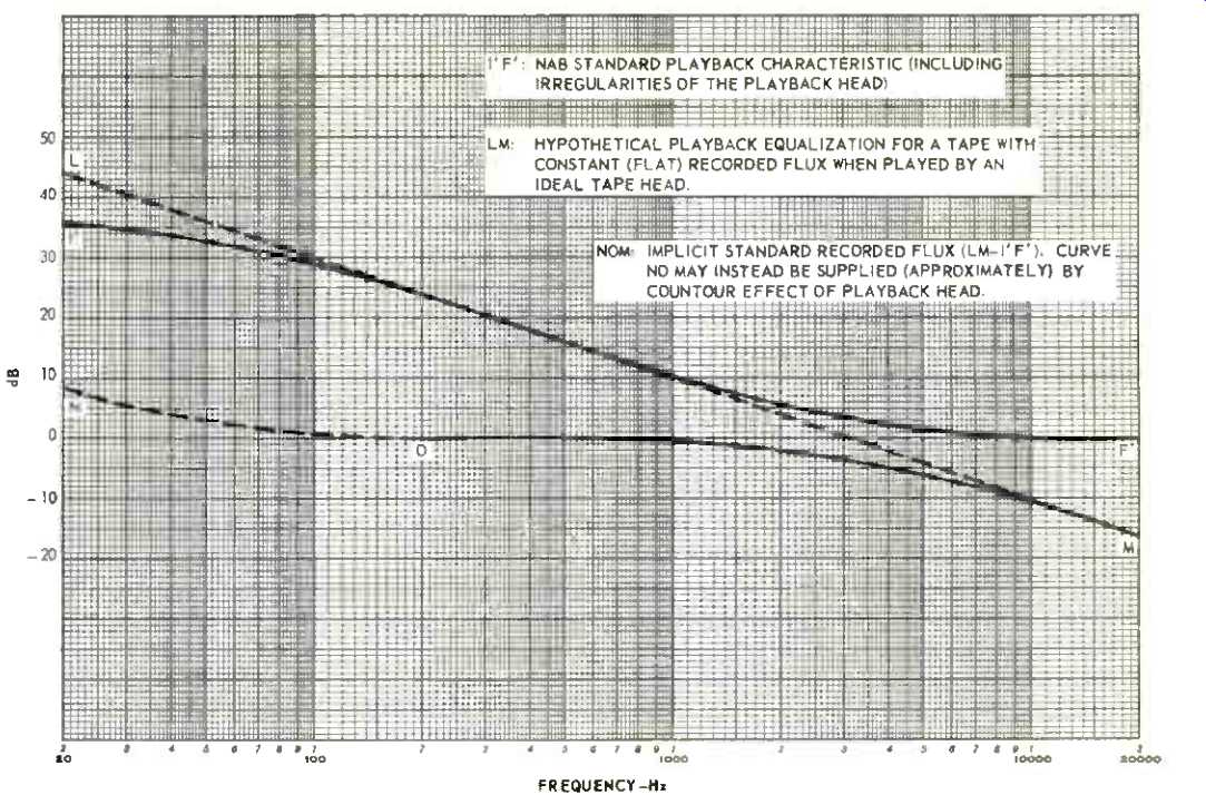
Fig. 5--NAB standard playback equalization and recorded flux.
To illustrate, assume that a playback head is significantly deficient in high treble; that is, its output rises with frequency but at less than the theoretical 6 dB per octave rate of an ideal head throughout the audio spectrum. Then, if flat response is to be maintained, the playback amplifier must supply enough treble boost to compensate for the head's deficiency. Together, the amplifier and playback head supply the NAB playback characteristic, Curve I'F' in Fig. 5 (or something like I'F' if the contour effect is pronounced). Without elaborate test equipment, how is one to ascertain whether a tape machine (playback amplifier plus playback head) provides the NAB playback characteristic? The answer lies in a standard test tape. (This is supposed to have been available from NAB by now, but hasn't yet been released.
In its place, the Ampex test tape is customarily used.) The test tape contains a series of audio signals recorded at such relative levels that a tape machine with the NAB playback characteristic will provide flat response when playing this tape. That is, a meter connected to the machine's output will read equal output level for all the test frequencies.
Accordingly the manufacturer of a tape machine designs the playback equalization circuit to yield flat response when playing the standard test tape. The equalization circuit allows for bass and/or treble irregularities of the playback head he uses-that is, departures of the actual head from the response of an ideal head (AD in Fig. 1). Some machines include adjustments which enable the technician or the user to touch up playback equalization on the basis of a test tape. It is then merely necessary to connect a meter to the machine's output, play the test tape (after making sure heads are cleaned, demagnetized, and aligned for azimuth), and touch up the playback equalization for flattest response as indicated by the meter. In some machines the VU meter can serve this purpose.
Now, what about treble boost in recording? Does NAB specify a treble recording characteristic in terms of what gets on the tape? Or does it specify a given amount of treble boost in the record amplifier, such as Curve E'J in Fig. 4? The answer is that, at least directly, NAB does neither. What NAB specifies is that, after playback equalization has been adjusted for flat response when playing a test tape, the record equalization should be adjusted for flat record-playback response.
There are good reasons for NAB snot specifying a specific treble boost curve in the record amplifier: (1) Treble losses in recording vary among types and brands of tape, so that the amount of required treble boost varies according to the tape which the manufacturer envisions will be used with his machine. (2) These losses vary according to the amount of bias the machine manufacturer elects to use. He tries to come fairly close to the bias which achieves minimum distortion. However, minimum-distortion bias may entail excessive treble loss, causing the manufacturer to reduce bias somewhat rather than increase treble boost in recording and thereby heighten the risk of overloading the tape. In other words, the manufacturer may find that the increased distortion resulting from a slight decrease in bias is not as bad as the increased distortion which would occur if more treble boost were used.
The NAB Recording Characteristic
Indirectly, NAB does stipulate a recording characteristic in terms of the relative levels of recorded flux on the tape at various frequencies in the audio range. To explain, let us repeat our dictum on recording/playback characteristics: "A given recording characteristic implies a complementary playback characteristic; or a given playback characteristic implies a complementary recording characteristic." Hence the NAB recording characteristic is Curve NOM in Fig. 5. Given playback characteristic I'F' and flat response, then the flux recorded on the tape must vary with frequency in the manner portrayed by NOM. NOM is derived as follows. We draw LM to show the hypothetical playback equalization required if the recording characteristic were flat and if an ideal playback head were used (or a playback head with its irregularities fully compensated in the playback amplifier). That is, LM declines 6 dB per octave with increasing frequency, thereby complementing the playback head's 6 dB rise per octave. However, any departure of the actual playback characteristic (I'F') from LM implies a corresponding (complementary) departure of recorded flux from a flat characteristic. Thus NOM is the difference between hypothetical and actual equalization, namely between LM and I'F'. At the low end, I'F' supplies less than the hypothetical bass boost. Therefore the deficiency must be made up in recording by bass boost NO (unless the deficiency is made up by the contour effect of the playback head). At the high end, I'F' does not drop as rapidly as LM; thus I'F' in effect is contributing treble boost. And a corresponding drop in treble must occur in recording, namely the treble decline of recording characteristic NOM. The implied recording characteristic NOM--flux on the tape--is the sum of magnetic losses in recording, equalization in the record amplifier, and response irregularities of the record head. All told and together with playback characteristic I'F', they produce flat response.
If, after all, there is an NAB standard recording characteristic, why doesn't NAB specify this explicitly (in the way that the RIAA phono recording characteristic and the FM broadcast characteristic are specified)? The answer lies in the kind and quality of laboratory test equipment required in order to measure recorded flux. It is far easier for the manufacturer, technician, or user to check the playback characteristic with the aid of a test tape and meter than to measure recorded flux. Since a playback characteristic implies a matching recording characteristic when overall response is flat, then if the playback characteristic is known to meet the standard (on the basis of playing a test tape) the recording characteristic perforce also meets the standard.
This signifies that if my tape machine and yours both have flat record-playback response, and if both produce flat output when playing the standard test tape, mine will record tapes that play back flat on yours, and vice versa.
We have several times commented on NO in Fig. 5. To bring things together, at the cost of repetition, this slight bass boost may be achieved by an equalization circuit in the record amplifier, by the contour effect of the playback head, or by a combination of the two. Even if there is no appreciable contour effect, the manufacturer may choose not to supply bass boost in recording. This is consistent with the NAB standard for frequency response, which permits record playback response to be down 3 dB at 50 Hz.
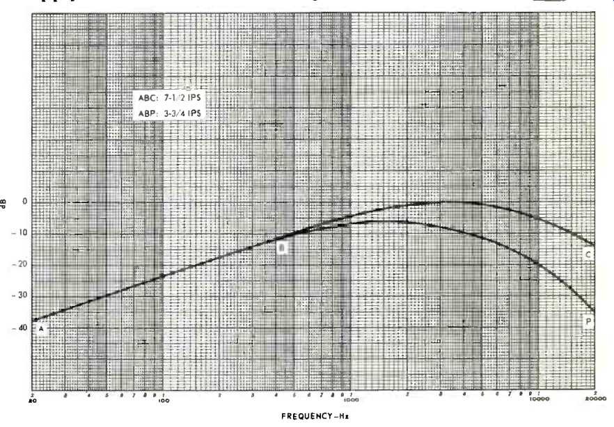
Fig. 6--Comparison at 7 1/2 and 3 3/4 ips.
Other Speeds, Other Tapes, Other Matters
All that we have said about problems and techniques of tape equalization at 7 1/2 ips also applies in essence to the lower (higher) speeds in home use. However, as speed is reduced, equalization must be changed, the principal reason being the greater magnetic losses that occur in recording at reduced tape speed. This is illustrated in Fig. 6, which compares unequalized record-playback response at two speeds, 7 1/2 and 3 3/4 ips.
Why do recording losses increase with reduced speed? The answer lies in the fact that these losses actually depend on recorded wavelength rather than on frequency as such.
We refer again to the length of the bar magnets that in effect are recorded on the tape. At a given frequency, a corresponding number of bar magnets are recorded per inch of tape. To illustrate, consider a 1,000 Hz tone, which is recorded as 2,000 bar magnets-one magnet for each positive portion of an audio cycle and one for each negative portion.
At a tape speed of 7 1/2 ips, the 2,000 magnets are recorded on 7 1/2 inches of tape, so that the length of each magnet is 7.5/2,000 inches or .00375". But at 3 3/4 ips, the length is 3.75/2,000 inches or .001875"-half as long. Earlier we pointed out that the shorter the wavelength (bar magnet), the greater the loss due to self-demagnetization and bias erase. Thus at a given frequency the wavelength is reduced and the recording loss is increased as tape speed is reduced. In going, say, from 71/2 to 33/4 ips, losses are of the same magnitude at 5,000 Hz as they were at 10,000 Hz at the higher speed; losses are of the same magnitude at 10,000 Hz as they were at 20,000 Hz; etc.
To offset the greater treble loss at low speed, more treble boost is needed in recording. But the requisite amount would of unequalized record-playback response overload the tape and cause excessive distortion. A viable alternative is to reduce treble boost and match this with reduced bass boost in order to attain flat response. As pointed out in our dictum on record/playback characteristics (in conjunction with Figs. 2, 4, and 4-A), reduced treble boost correspondingly calls for reduced bass boost in order to achieve flat response.
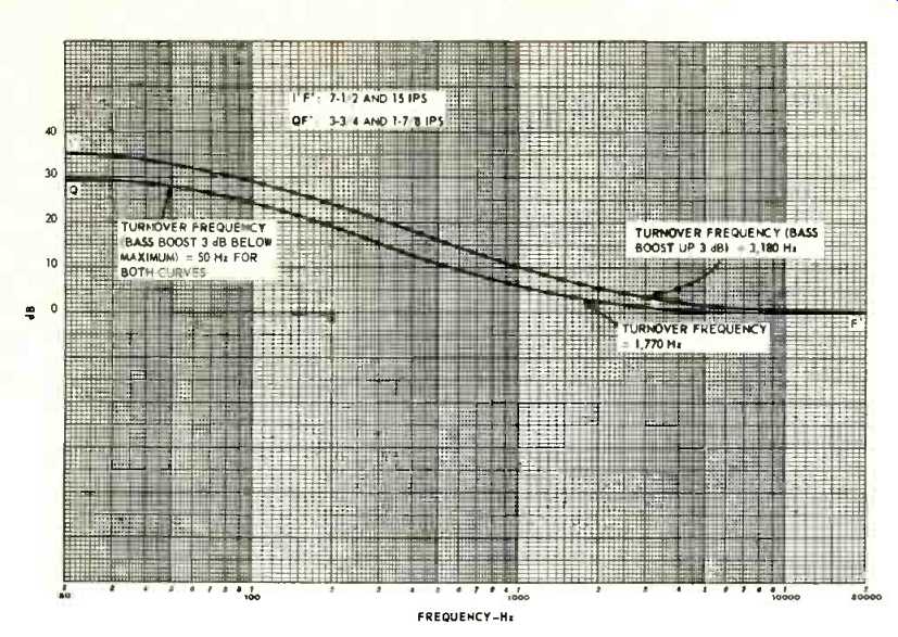
Fig. 7--NAB standard playback equalization curves (including playback head
characteristics).
In this light the NAB standard for 3 3/4 and 1 7/8 ips calls for a playback characteristic with 5 dB less bass boost than the characteristic for 7 1/2 ips (which is also the playback characteristic for 15 ips). Fig. 7 shows the two playback characteristics. Curve I'F' is the NAB standard characteristic for 7 1/2 and 15 ips, and QF' is the standard for 3 3/4 and 1 7/8 ips.
I'F' entails a total of 36 dB bass boost; QF', 31 dB. In technical terms, I'F' is described as having turnover frequencies of 3,180 and 50 Hz (or, respectively, time constants of 50 and 3,180 microseconds). This signifies that the curve has achieved 3 dB boost at 3,180 Hz, and at 50 Hz is 3 dB below maximum boost. QF' has turnover frequencies of 1,770 and 50 Hz (or, respectively, time constants of 90 and 3,180 microseconds), signifying 3 dB boost at 1,770 Hz, and boost 3 dB below maximum at 50 Hz. (The relationship between time constant t in microseconds and turnover frequency f in Hz is expressed by t = 159,155/f. The factor 159,155 derives from the technical relationship between the values of capacitance and resistance needed in an equalization circuit to achieve a 3 dB change in frequency response.) According to Fig. 7, two playback equalization characteristics are used for four speeds, one characteristic for 7 1/2 and 15 ips, and the other for 3-3/4 and 1-7/8 ips. But the sense of this article is that each tape speed requires its own equalization in order to obtain optimum results with respect to frequency response, S/N, and distortion. In other words, why don't we have four standard equalization characteristics instead of two? The indicated answer is that four characteristics would complicate matters too much for those making tape machines, and perhaps for those using them. An equalization characteristic appropriate for a given speed can be used for the next higher speed without undue departure from optimum performance. So all in all, two playback characteristics for four speeds affords a practical compromise without unduly deleterious consequences.
What happens to equalization requirements as tape formulations change, resulting in higher output, lower noise, better treble, different bias requirements? So far as playback equalization is concerned, the answer in essence is nothing, or very little. Essentially it is only record equalization that changes (except in the unlikely event that changes in tape formulation would someday result in a new standard playback characteristic, which would be a very unhappy day for those with substantial collections of recorded tapes). If a new tape has increased treble output, the tape machine manufacturer may choose not to extend treble response but to reduce the amount of treble boost supplied by the record amplifier, thereby lessening the chance of tape saturation. Alternatively, he can leave treble boost about the way it was, and increase bias to achieve less distortion, yet without reducing treble. Or, in increasing bias, his purpose may be not to reduce distortion but to permit recording at a higher level at the same distortion as before, thus improving S/N. Or the manufacturer may follow a compromise course which results in some combination of improvements in treble response, distortion, and S/N. If a new tape has higher output, the machine manufacturer can in similar fashion take advantage of this to improve S/N, treble response, distortion, or a combination of them.
Higher tape output enables the machine to apply somewhat less signal to the tape without sacrificing S/N; hence there is less danger of tape saturation, permitting more treble boost for better treble response; or permitting more treble boost together with more bias for lower distortion. Higher tape output enables the machine to reduce recording level for less tape distortion. Higher output enables the machine to keep bias and treble boost as before, with an increase in recording level to achieve higher S/N, yet without increase in distortion.
In similar ways, reduction in tape noise not only permits higher S/N but can also be translated into improvements in distortion and treble response, which might entail changes in treble boost, bias, or recording level. Changes in a tape's bias requirements do not in themselves entail changes in treble equalization. However, changes in bias requirements for a tape tend to accompany changes in noise, treble, and output characteristics of the tape, and it is then that the machine manufacturer may find it advisable to change record equalization.
Does use of the Dolby noise reduction system (or other noise reduction systems such as the Burwen) affect tape equalization? The answer, essentially, is only in recording if at all. Introduction of the Dolby system in a tape recorder installation does not necessarily call for a change in recording equalization. One records as before, except than the incoming signal first goes through a treble-boosting Dolby circuit; and one plays as before, except that the playback signal afterward goes through a matching treble-reducing Dolby circuit to achieve noise reduction and restoration of flat response. Overall record-playback response is not changed by Dolby, which therefore does not compel a change in tape equalization.
On the other hand, the Dolby (or a similar) system may invite changes in equalization for reasons already suggested here. To illustrate, assume that Dolby achieves a 10 dB reduction in noise. The tape machine manufacturer might decide to sacrifice part of this improvement, say 4 dB, in exchange for better treble response. He could adjust the tape machine (adjust the reading of the record-level indicator) to operate at 4 dB lower recording level, permitting 4 dB more treble boost without increase in danger of tape saturation. Or he could exchange part of the Dolby reduction in noise for improvement in distortion, by using more bias along with more treble boost, as well as a lower recording level. Or he could achieve some improvement in all three respects-noise, treble response, and distortion.
(Audio magazine, Oct. 1972; Herman Burstein)
= = = =