By Robert Berkovitz and Kenneth Gundry [Dolby Laboratories, Inc. ]
The Dolby B-Type Noise Reduction System
The Dolby B-Type circuit is a specialized form of compandor which avoids the usual deficiencies of compandors. The operational principle of the B-Type system is complementary low-level compression and expansion in a frequency range which varies in bandwidth as the signal changes.
Most objectionable noise encountered in home listening is at middle and high frequencies, from about 500 Hz to the upper limit of audibility. In the interest of circuit economy, the action of the B-Type circuit has therefore been limited to this range. A feedback control circuit adjusts system parameters automatically as a function of signal level and spectrum, so that the system's action complements the psycho-acoustic masking of noise which occurs naturally in the course of the program. A block diagram of a Dolby type of noise reduction system is shown in Fig. 3. The circuits used for encoding (during recording or transmission) and decoding (during playback or reception) are quite similar and can be considered as the same circuit, switched to operate in either mode.
The compression and expansion characteristics of the Dolby B-System are fixed and are referred to Dolby Level, a specific internationally standardized reference level. In the case of cassette tape, Dolby Level is a flux of 200 nWb/m; in FM broadcasting, Dolby Level is ± 37.5 kHz deviation.
Figure 4 is a block diagram of a switchable (encode-decode) B-Type circuit. There are two paths which the input signal follows: a main path (at the lower part of the figure) in which no change other than linear amplification occurs, and a secondary path, a variable filter through which only low-level, high frequency components of the input signal are allowed to pass. To encode the signal, the output of the secondary path is combined with signal in the main path additively; this boosts low-level, high frequency portions of the signal. Decoding is accomplished by feeding the secondary path from the circuit output, which is opposite in phase to the input (note phase inverter in Fig. 4); the secondary path is then part of an a.c. negative feedback loop which reduces output, i.e., the output of the secondary path is combined with the main path subtractively. In the decode mode, therefore, the circuit reduces the level of precisely the same information which was increased in level during encoding.
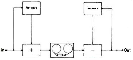
Fig. 3-Block diagram of Dolby type noise reduction circuit as used in
typical record-reproduce chain.
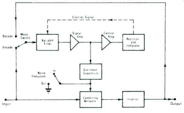
Fig. 4-Block diagram of Dolby B-Type noise reduction circuit. The configuration
shown can be switched to encode or decode the signal.
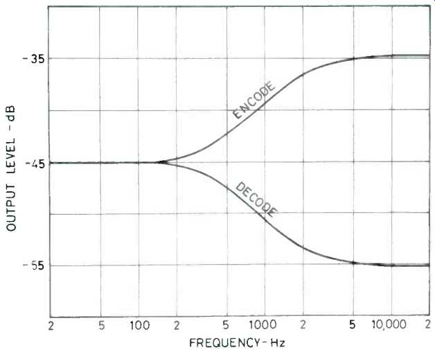
Fig. 5-Output of B-Type encoder and decoder circuits under low-level
input signal conditions. The two operations are symmetrical and the result
is an overall frequency response which is level.
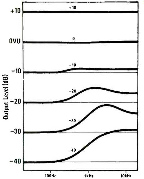
Fig. 6-Characteristics of encoding processor at several levels. The
gradual reduction in boost with increasing level avoids possible tape
overload.

Fig. 7-Effect of the B-Type circuit on a tone burst; frequency = 3 kHz;
burst duration, 12 milliseconds; low level = 40 dB; high level = +6 dB;
(A) Input to system; (B) Encoded, (C) Encoded and Decoded.
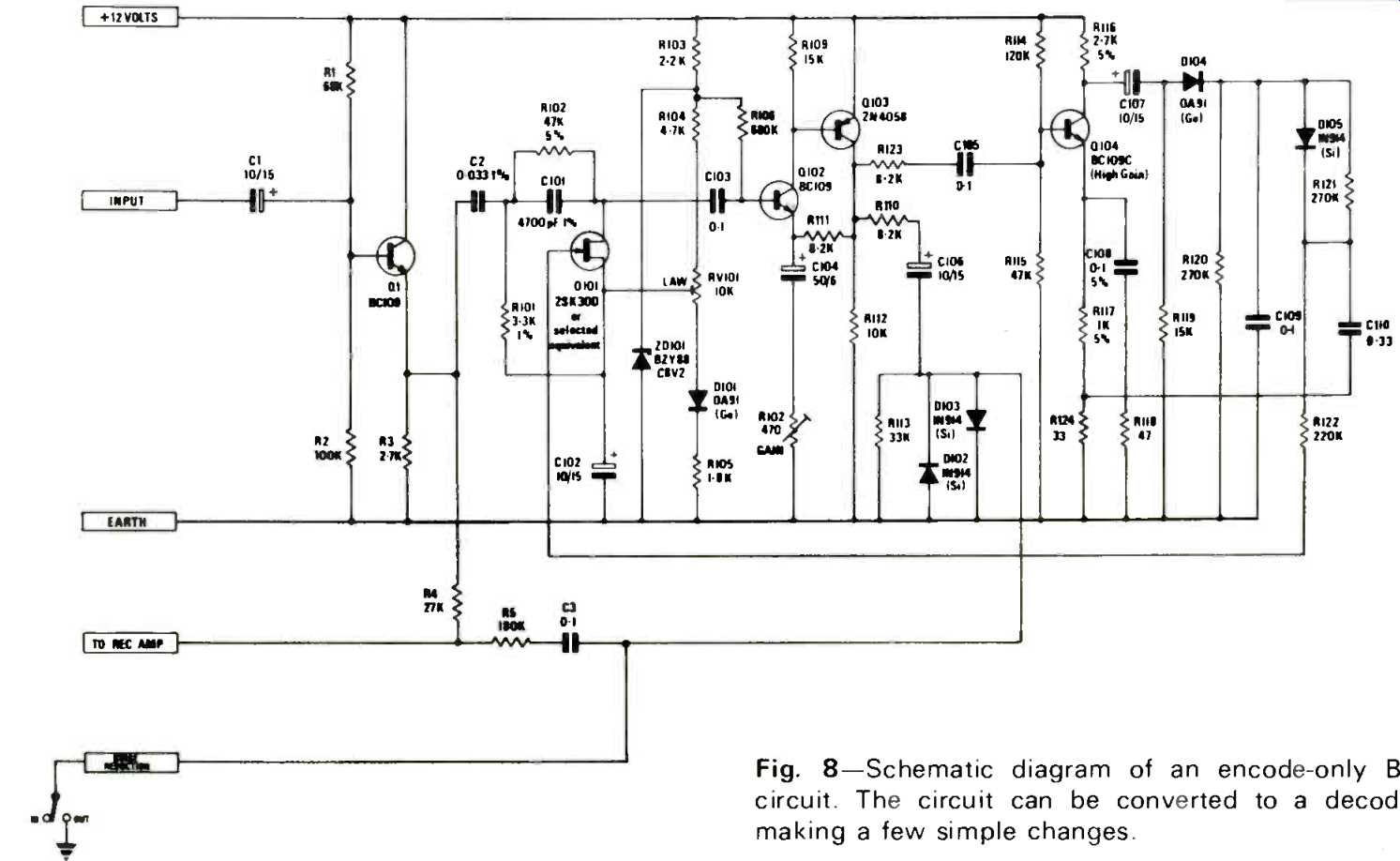
Fig. 8-Schematic diagram of an encode-only B-Type circuit. The circuit
can be converted to a decoder by making a few simple changes.
As Fig. 4 indicates, the action of the B-Type circuit is controlled by the output of the filter in the secondary path.
Above a fixed threshold level, the bandpass of the filter, in turn, is modified by the d.c. feedback loop.
At very low levels, i.e., below the threshold, which at high frequencies is about 40 dB below Dolby Level, the output of the filter is not sufficient to generate d.c. feedback; consequently, the output of the secondary path is simply proportional to signal level within the filter pass band. The output of the circuit is then essentially as shown in Fig. 5.
As signal level rises above the threshold level, the rectified filter output is returned to the FET gate where it is applied as negative feedback; raising the filter cutoff frequency so that the output of the secondary path, while still increasing, no longer does so in proportion to the change in signal level.
As signal level becomes even larger, the increasing d.c. feedback generated restricts the filter bandwidth further, and near Dolby Level the output of the secondary path remains relatively constant. The net effect is that the secondary path has no audible effect on output at low frequencies, and increasing effect with increasing frequency and decreasing level to about 40 dB below Dolby Level. At high levels, the effect of the extra signal is so small as to have no significance; at low levels, in the spectral region in which noise reduction is required, the increase during encoding is as much as 10 dB, and is of considerable importance.
The manner in which the secondary path changes from constant-gain to constant-output is determined by the adjustment of gain within the feedback loop. In addition, the exact variation in filter bandpass with changing level is set optimally by making the control amplifier frequency-dependent. The overall frequency response of a B-Type encoder circuit for different input levels is shown in Fig. 6.
A compandor operating over a wide frequency range must be designed to take into account the problem of noise modulation discussed above. If some high-level passages in the program differ sufficiently in frequency content from the noise components present, the latter will remain audible during the program in many cases. However, these passages cannot be increased in level when encoded, because of the danger of overmodulation. Under these conditions, compression may be applied intermittently, and high-frequency noise modulated audibly by mid-frequency components of the signal. The B-Type circuit overcomes this problem because it continues to function when a high-level signal occurs within its operating range; instead the feedback control shifts the range upward in frequency. This avoids the danger of over-modulation, but retains full noise reduction at frequencies higher than those masked by the signal.
The attack time of the B-Type circuit is dependent on the amount and rapidity of the signal change, due to the nonlinear design of the integrator, varying from about 100 milliseconds to as little as 1 millisecond. The recovery time of the rectifier-integrator is shorter than that of the human hearing system, about 100 milliseconds.
All compressors exhibit overshoot, including the B-Type circuit. However, the dual-path approach used makes it possible to reduce the amplitude of overshoots significantly.
Overshoot, which can occur only in the secondary path (where it can be suppressed without affecting the main signal) is comparatively small, and essentially disappears when the signal is decoded again. When signal levels are low, or when changes in signal level take place slowly, there is no overshoot problem; when signal changes are large and rapid, diodes in the overshoot suppressor stage limit the peaks of the overshoot. Since this takes place in the secondary path, the result of the suppressor action is to limit overshoot to a relatively small fraction of the full-level main path signal.
Further, by restricting overshoot suppression to the secondary path, it is possible to avoid introducing audible distortion to the encoded signal. Because a complementary action takes place during decoding, the small remaining overshoot in the encoded signal is eliminated, and as with other effects produced during encoding, the original signal is restored.
Figure 7 shows the result of encoding and decoding a short burst of 3 kHz, which changes in level from -40 dB to +6 dB.
Figure 8 is a typical schematic diagram of an encode-only B-Type circuit; the circuit for decoding-only is similar. As can be seen, only five transistors plus an FET are required; the parts cost of the circuit is approximately $2.40. Figure 9 is the schematic diagram of a B-Type processor which has been designed to integrate noise reduction with other tape recorder electronics requirements as much as possible. The resulting circuit provides 26 dB of gain, whether or not noise reduction is in use, bias and multiplex filtering, and meter and monitor amplifiers. In fact, the only additional electronics needed to complete the recorder are a bias oscillator, recording amplifier (one transistor) and a microphone and head amplifier (two transistors). With the active elements used in the record/play switchable processor shown (eight transistors and one FET), the total used in the recorder, for two channels, is 22 transistors and two FET's.
The cost to a manufacturer of the components shown in Fig. 9 is about $3.20, excluding the bias and multiplex filter components, which are, of course, necessary in the circuits of any properly designed tuner and recorder.
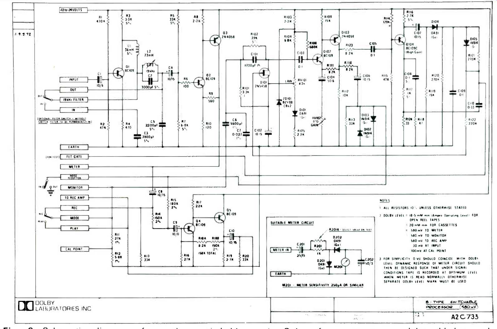
Fig. 9--Schematic diagram of complete switchable gain. Only a few more
parts need be added to make encode/decode circuit for use in tape recorder,
including complete record/play electronics for one channel of HF filtering,
meter drive, monitor output and 26 dB of the recorder.
Dolby Laboratories and Signetics have collaborated in the development of an integrated-circuit version of the B-Type circuit. The IC is expected to offer manufacturers economy of assembly, elimination of adjustments, and somewhat smaller space requirement than the discrete-component version.
The characteristics of Dolby B-Type noise reduction can be summarized as follows:
1. Program recovery characteristics, with regard to frequency response, phase response, transients, and signal dynamics, are theoretically perfect; in practice, this ideal is attainable to any desired accuracy. Distortion in practical B-Type circuitry is considerably lower than that ,of the tape recorders or tuners with which it is used. Any type of program material can be encoded and decoded without audible loss.
2. The circuit is 'simple, inexpensive, and small in size, either in discrete-component or IC form.
3. The circuit is easy to manufacture and use because of the absence of critical components or adjustments. The circuit can be quickly and easily calibrated during manufacture, after which further calibration is not required. In use, only a simple level adjustment is necessary if tape of significantly different sensitivity is substituted for that formerly used.
4. No modification of broadcasting or duplicating practice is required to incorporate B-Type encoding. The use of the noise reduction system often makes worthwhile other improvements, however, such as extension of frequency response and dynamic range, or reduction of distortion by use of lower modulation levels, or some combination of these.
Effects Upon Noise Spectra
Figure 10 is a multiple exposure of the screen of a 1/3-octave real-time analyzer, allowing a direct comparison of the noise spectra at the output of a high-quality cassette recorder when different kinds of tape were used with and without the Dolby B-Type noise reduction circuit. Curve I is that produced by C90 ferric oxide tape; curve 2 is that of C90 chromium dioxide tape; curve 3 is produced by the same tape used for curve 1, but the B-Type circuit is, switched "in," and curve 4 represents the noise spectrum of the chromium dioxide tape with the circuit in. The tapes shown were biased before the measurements were made; no changes in gain or other control settings were made during the tests, other than to set equalization differently for the chromium dioxide tape from (70 microsecond). In fact, most of the improvement in noise level obtained when chromium dioxide tape is used appears to be due to the change in equalization; if this change is not made, there is little advantage in chromium dioxide tape from a noise point of view. On the other hand, the combination of chromium dioxide tape, 70 microsecond equalization, and B-Type noise reduction results in an excellent noise figure, 57 dB below Dolby Level in the example in the photograph (DIN 45405). The advantages of B-Type noise reduction are also obtained when the system is used for FM broadcast transmission and reception, i.e., the improvement in signal-to-noise ratio obtained by use of the B-Type circuit is approximately the same as that produced by a 10 dB increase in field strength.
The significance of this improvement can be appreciated when it is realized that such an increase would usually require an increase in transmitter power by a factor of ten.
Considerable experimentation and broadcast experience in the USA have demonstrated, as one would expect, that the area in which listening is satisfactory is greatly extended by use of the B-Type noise reduction system. Several American classical music FM stations are already broadcasting fulltime using Dolby B-encoding.
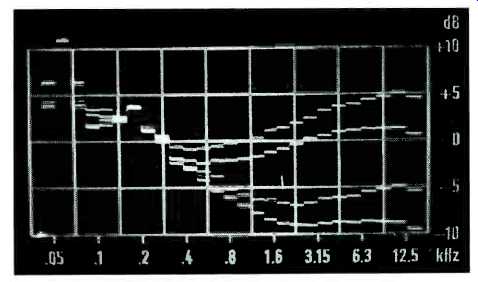
Fig. 10--Noise spectra at output of cassette recorder during playback
of four kinds of tape. All tape was biased and control settings were
the same for the four tests. (1) Ferric oxide C90 low-noise,-45.7 dB
DIN 45405; (2) Chromium dioxide C90,-48 dB; (3) Same as (1) with B-Type
noise reduction, -55 dB; (4) Same as (2) with B-Type noise reduction,
-57.1 dB. All noise measurements referred to Dolby Level = 200 nWb/m.
Compatibility
When any improvement is made in a system as widely used as the compact cassette system, it is highly important that the new development should be fully compatible with existing equipment. Improved cassettes must be playable on any machine which can play old-type cassettes, and fortunately this is true of Dolby B-Type cassettes. Such cassettes are subjectively compatible (i.e., generally pleasing to the listener) when played without decoding circuitry, to a great extent because of the unique approach taken in the B-Type circuit.
Because most low-cost cassette machines are deficient in high-frequency response, the increase in low-level high frequency content in a B-Type cassette is usually welcomed by listeners with such equipment. Cassette recorders of higher quality, or the associated equipment with which they are used, contain tone controls which permit the balance to be adjusted to suit the taste of the listener. It is quite likely that many of the millions of B-Type encoded cassettes which have been made commercially are owned and played by listeners who are unaware of the special nature of the program material they hear. In any case, the subjective difference between encoded and other cassettes is sufficiently unobtrusive that none of the recording companies offering "Dolbyized" cassettes have found it necessary to offer old-type cassettes as an alternative.
It is worth noting that almost all pre-recorded cassettes are already compressed, for only in this way can the audibility of low-level passages be preserved in programs of wide dynamic range. B-Type cassettes differ mainly in that the listener now is able to remove the compression by pushing a button on his cassette machine restoring program dynamics and reducing noise. This is only possible because B-Type compression is standardized, while other types of compression vary considerably.
Commercial Use
Within a few years of its introduction, the Dolby B-Type noise reduction system has been licensed to most major manufacturers of consumer tape recorders. At the present time there are more than 40 licensees manufacturing over 100 different B-Type products. Licensee payments for use of the circuit are on a sliding scale, based on quantity, from a maximum of 50¢ ( U.S.) to 10e per circuit. Royalty charges are typically 60e per stereo unit for a major manufacturer.
In addition, most of the pre-recorded cassettes now made in the United States, the United Kingdom and Japan are "Dolbyized," and many of the largest recording companies issue their cassette output in this form, among them Ampex and CBS in the United States, Decca and RCA in England, and CBS-Sony, Nippon Columbia, King, and Apollon in Japan. Pre-recorded open-reel tapes and 8-track cartridges are also becoming available. In the United States, a number of FM stations have already started to broadcast regularly in B-Type encoded form, and this procedure is under study in other countries as well. There is no royalty payable for encoding cassettes or other tape recordings, or broadcasts.
Conclusions
The reduction of background noise by the Dolby B-Type noise reduction system has contributed importantly to the improvement in quality of home tape recording and playback. It has helped to make the extension of frequency response, the reduction of wow and flutter, and other improvements worthwhile, particularly in cassettes. The unique characteristics of the B-Type system permit excellent noise reduction without program losses, noise modulation and other drawbacks which have afflicted earlier attempts to solve the noise problem. The simplicity and economy of the B-Type circuit facilitate its use in consumer products at all price levels.
==========
(adapted from Audio magazine, Oct. 1973)
Also see:
Dolby B-Type Noise Reduction System--Part 1 (Sept. 1973)
Dolby C-Type Noise Reduction (May 1981)
Introducing Dolby S-Type Noise Reduction (Jun. 1990)
EQ & NR: Striking A Balance (Aug. 1988)
Deck to Deck Matching and NR: Straightening the Mirror (Aug. 1986)
= = = =