by M. B. Martin [Memorex Corporation]
THE PURPOSE of this article is to discuss a relatively small number of factors which affect the quality of recording and reproduction from cassette tape. The discussion is confined to considerations which came to light as part of the work of developing a new cassette tape and no attempt is made to completely analyze the cassette recording system.
The modern cassette tape system has reached a point where high fidelity sound recording and reproduction is a proven fact and effective competition with the phonograph disc is technically feasible. The development from the high noise, low quality system to the present state has been unusually rapid; one of the reasons being that the standards of tape speed and recorded track width have been adhered to, thus permitting technical development to be applied to improving quality and not to achieving greater economy of tape or providing a larger number of tracks per unit width. In the past, technical improvements in magnetic recording have, to a large extent, been applied to the economics of the system; whereas, with phonograph records, the standards have been fixed over long periods of time permitting developments to be applied to the improvement of quality thus, at the consumer level, the phonograph record has always been able to compete with tape from a quality of sound viewpoint, as well as being a more easily handled medium at a lower price per playing minute.
As part of the design project for a new cassette tape, the cassette recording system was analyzed to better understand demands made upon the recording media by the hardware and current recording standards. The work included a study into the effects of noise reduction systems, the relationships between recording head gap length and coating thickness, and some brief investigation into the energy spectra of music. The latter investigation confirmed the belief that, in many ways, the best method of testing to provide the most meaningful results, in relation to music recording, is to use as the signal source pink noise, the energy of which reduces at the rate of three dB per octave as frequency increases.
The Test System
Much of the data presented was generated by the use of white or pink noise as the signal source and a General Radio Real Time Analyzer, Type 1921, as the detection system. Frequency response curves, music spectra, and spectrum analysis of noise are printed out by the analyzer on an X-Y Plotter.
When white noise is used as the signal source, the analyzer is adjusted to have a sensitivity which reduces by 1 dB for every third octave with increasing frequency; under these conditions a system with a flat frequency response will produce a horizontal line printout. When pink noise is used, the analyzer is set to a flat response so that a system with a flat response will also produce a horizontal line printout.
The frequency response data presented here was analyzed using an integration time of eight seconds, system and tape noise spectra were taken with an integration time of eight seconds, and a variety of integration times up to 32 seconds were used for the analysis of music spectra. This method of taking data has a number of significant advantages; two worthy of mentioning are:
1. Families of related curves can be plotted in a period of time short enough to permit the exclusion of system drift effects from consideration as affecting measurement accuracies.
2. The use of pink noise tests the tape and system under conditions which are a good approximation to those generated by modern music incorporating electronic synthesizers, heavy percussion, and electronically assisted string instruments.
All data presented in this article was taken on recorders which have very low electronics noise and, therefore, the signal-to-noise performance is dependent on the tape characteristics alone. Unfortunately, in real life, this is not always the case; the author has seen more than a few so-called high fidelity cassette recorders where the electronics noise predominates.
With modern solid state circuitry, this is unforgivable particularly when, as so often happens, the recording amplifier is so noisy that the recorded noise completely obscures the bias noise of the tape. Obviously, with such a machine, there is no way that a better tape can improve the situation.
Tapes
Reasonable high fidelity recording and reproduction can be achieved with four classes of tape. Listed in order of appearance on the market as cassette tape, they are:
1. Low noise, high output tapes;
2. Chromium dioxide tapes;
3. Chemically modified gamma ferric oxide tapes-cobalt or Fe2O4 (magnetite) doped particles, and
4. Highly developed gamma ferric oxide tape such as MRX2.
The characteristics of the tapes are determined by the magnetic particle used. Within each of the four categories, there will be differences in performance from manufacturer to manufacturer determined by the differences in the processing and formulations of the binder system used by each company.
Category 1: Low noise, high output tapes, use a magnetic particle which is unmodified gamma ferric oxide (gamma F2O3). The improvement in performance over the earlier ferric oxide tapes is achieved by a reduction of particle size and some improvement in shape. The particle still is troubled by the presence of protuberances known as dendrites and holes and the important length/width ratio varies from 4:1 to 6:1.
Category 2: Chromium dioxide, is a synthetic compound with magnetic properties that are, in some ways, superior to those of ferric oxide. The fundamental particle size is approximately the same as the iron oxide particles in category 1, but its shape is almost perfect, being a single crystal with a length to width ratio of 8:1 with no dendrites or holes. In addition, the coercivity is higher, 500 oersted as compared with 300 approximately. As a result of the better shape, the particles can be more accurately aligned in the direction of tape travel which, with the high coercivity, results in a much improved magnetic performance at the short wavelengths; i.e., high frequencies.
Category 3: The chemically modified gamma ferric oxide particles, are, in size and form, the same as the pure ferric oxide used in category 1. The improvement in performance is obtained by the addition of carefully controlled small amounts of impurities; either metallic cobalt or magnetite (Fe2O4), another oxide of iron. The effect of these impurities is to raise the coercivity of the particle and increase its magnetic efficiency. The formation of the crystal is not improved.
Additionally, there is a tendency for chemical instability which results in some magnetic instabilities under certain conditions which can easily occur in practical use. There have been several short-lived attempts to make tapes from these types of particles over the past 38 years. Time alone will tell whether today's particle chemists have solved the problems.
Category 4 uses a pure ferric oxide particle chemically identical with that used in category 1 which means that it has all the inherent stability and other properties which have made gamma Fe2O4 the only wholly successful magnetic compound of iron for tape since its introduction in 1936. The improved performance is obtained entirely because of a perfected crystal shape with a length/width ratio of approximately 10:1. The absence of dendrites and holes gives the tape designer the capability of increasing the magnetic density and, hence, the magnetic efficiency of the coating. Much better orientation is also achieved and the resulting tape is considerably more efficient at all frequencies. Because of the better particle packing, dispersion, and orientation, the undesirable modulation noise effects caused by magnetic discontinuity are significantly reduced. At the time of writing, we believe MRXZ is the only cassette tape containing this magnetic oxide.
Figure 1 shows the differences in the frequency response of these four categories of tape at 1 7/8 ips when recorded with the bias carefully optimized for each and the signal recorded at a level 20 dB below that level which gives 2% total harmonic distortion at low frequencies. For the purpose of showing the differences in response between these tapes, the recording pre-emphasis was maintained at the optimum for the perfected gamma ferric oxide. The chromium dioxide essentially has the same output; i.e., the same sensitivity at low frequencies as the low noise, high output tape, whereas the cobalt modified and the perfected particle have a higher output at the long wavelengths resulting from approximately 2 dB greater sensitivity and the ability to accept a higher recording signal. The perfected particle also has a greater efficiency at the high frequency or short wavelengths which result in up to 8 dB more sensitivity at 10 kHz at 1 7/8 ips when compared with high output, low noise ferric oxide tapes and about 2.5 dB less sensitivity than chromium dioxide tape.
Figure 2 gives typical bias output curves for each of the four types of tape at three signal frequencies, 333 Hz, 3kHz and 10 kHz. The optimization points for the three ferric oxide tapes are very similar provided the criteria of optimization is that over-bias which reduces 10 kHz signal by 3' dB. As is well known, chromium dioxide requires approximately 40% more bias current to provide adequate biasing field. Decreasing the bias slightly would obviously improve the high frequency performance; however, this is undesirable from the point of view of long wavelength distortion and it also increases the susceptibility to drop-outs caused by surface asperities.
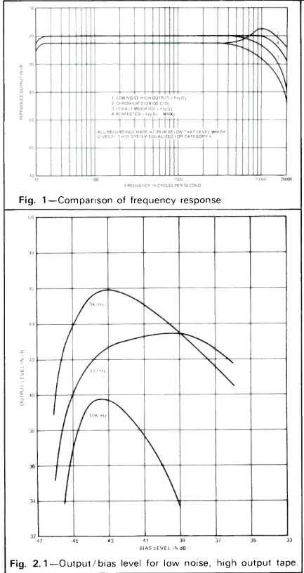
Fig. 1--Comparison of frequency response. Fig.
2.1--Output/bias level for
low noise, high output tape.
As with any other magnetic recording system, the highest biasing frequency possible should be used to minimize modulation noise and beat effects. The data given later in this article was taken with a bias frequency of 102 kHz and the even harmonic distortion present in the bias waveform was 0.05% second harmonic. This low even-order harmonic distortion is essential to minimize the effects of d.c. noise and second harmonic distortion of the signal due to unbalanced bias waveform.
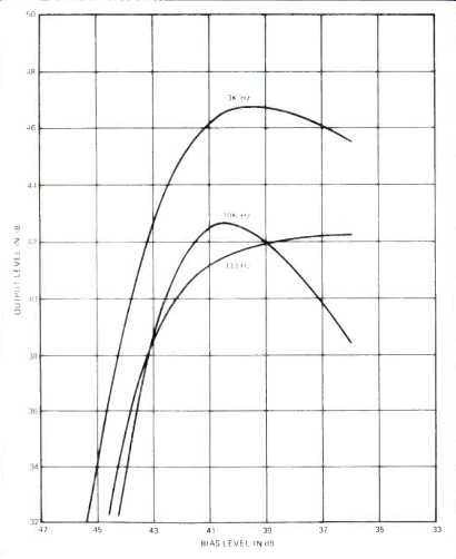
Fig. 2.2--Output/bias level for chromium dioxide tape.
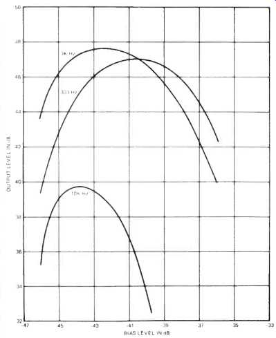
Fig. 2.3-Output/bias level for cobalt modified tape.
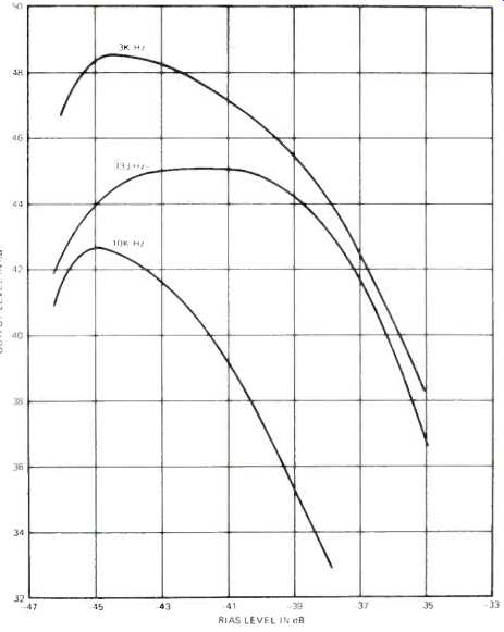
Fig. 2.4-Output/bias level for improved gamma ferric oxide tape
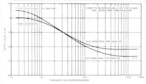
Fig. 3--Equalization energy standards.
Equalization
The standard replay equalization for cassettes operating at 1 7/8 ips has a bass roll-off created by a circuit with a time constant of 1590 microseconds and a high frequency boost with a 120 microsecond time constant. Recently, a second equalization standard has been proposed to permit fuller use of the characteristics of modern tapes, specifically chromium dioxide. The new proposed standard has a low frequency roll-off of 3180 microseconds with a 70 microsecond equalization curve at the high frequency and recorders are now on the market which use this proposed standard.
The two replay characteristic curves are shown in Fig. 3. The old standard has the advantage that with improved high frequency performance of tapes, the high frequency compression generated by tape overload is significantly reduced because of the reduced recording pre-emphasis required to produce a flat frequency response. However, under these conditions, the use of chromium dioxide would not significantly improve signal-to-noise ratio of the system when compared with the same system using low noise tape; it would only result in an extended frequency response and reduced modulation noise. The proposed new standard improves the signal-to-noise ratio at the expense of the greater risk of high frequency compression; however, with chromium dioxide, this compression is no worse than with low noise, high output ferric tapes using the 120 micro-second equalization curve.
Excellent results can be achieved by using the same recording pre-emphasis for both chromium dioxide and low noise tape by switching the bias and replay equalization leaving the recording pre-emphasis the same for both tape types.
The change at the low frequency end reduces the risk of low frequency distortion. A good case can be made for eliminating all low frequency pre-emphasis in the recording process and, thus, removing the need for the roll-off at low frequencies on replay. With modern solid state circuitry, the elimination of power line generated noise is relatively simple and inexpensive. The reason for the low frequency de-emphasis on replay was to simplify the electronics designers' problems with hum. The reason no longer exists with cassette tape and the heavy bass which is characteristic of much modern music makes it painfully difficult for a duplicator to record a satisfactory cassette without low frequency overload.
The elimination of this bass equalization would significantly assist in this problem.
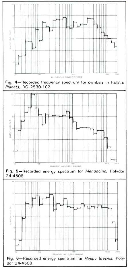
Fig. 4--Recorded frequency spectrum for cymbals in Holst's Planets,
DG 2530-102.
Fig. 5--Recorded energy spectrum for Mendocino, Polydor 24-4508.
Fig. 6--Recorded energy spectrum for Happy Brasilia, Polydor 24-4509.
Music Before considering further the demands placed upon cassette tape by equalization and signal-to-noise ratio improvement systems, it is appropriate to examine the energy spectra of the musical sources available. The most likely source of high quality signal within the scope of the home user is the phonograph record; few users have a better source of quality music, such as high speed master tapes, and with the average standard or quality exhibited by today's FM broadcasters, even when they are transmitting from tape, the transmission quality is such that it rarely reaches the fidelity available from even moderate quality discs.
Analysis of the spectra of two or three disc selections by means of the GR Real Time Analyzer gave the spectra shown in Figs. 4 through 6. Figure 4 is the spectrum of a cymbal crash from Deutche Grammophon's recording of the Boston Symphony/Steinberg performance of the Holst Planets Suite.
As can be seen, there is considerable high frequency energy to the limits of the analyzer at 20 kHz and the energy from 125 Hz through 5 kHz approaches a horizontal line which, with the setting of the analyzer used, means that the energy was reducing at the rate of 3 dB per octave with rising frequency. Figure 5 is from a record made by a combination using a wide variety of percussion instruments with very strong electronically generated bass. In this record, energy is concentrated around the bass tones at 80 Hz and falls off fairly rapidly up to the limits of 10 kHz where apparently the record cuts off. Figure 6 is of some Latin American music, using heavy orchestration with percussion, electronic instruments and brass; this disc has an energy spectrum approaching that of pink noise. These examples by no means represent an exhaustive study; however, they do point to the fact that discs can easily be found with a very wide recorded bandwidth and high energy levels at the extremes of the band.
The duplicator of music cassettes obviously has to cope with tape masters having energy at high levels over the whole of audible band which present a formidable problem to him.
It would appear from these analyses that the use of pink noise to study the behavior of a recording system is a test technique with greater validity than the use of pure sine waves at discrete frequencies.
The use of recording pre-emphasis which rises at high frequencies at a rate greater than 3 dB per octave will eventually result in tape overload when trying to record, from records such as those analyzed, if the record level indicators do not take account of the modified frequency characteristic created by the pre-emphasis. "Flat" level indication presumably is used by equipment designers on the assumption that musical spectra still conform to the classical spectra published in most of the literature which show considerably reduced energies at the very low frequencies and at frequencies above 5 kHz. Modern orchestration involving the use of synthesizers and electronically reinforced instruments has changed the picture.
The Compromise
The problem of establishing good high fidelity performance and the choice of equalization resolves itself into a compromise between tape overload or compression at the short wavelengths and a good signal-to-noise ratio. Pre-emphasis in the recording mode reduces the replay equalization necessary at the price of the reduction in high frequency performance at high signal levels with, consequently, high intermodulation distortion; the benefit of this choice is that the reproduced tape noise is lower than with a system where most of the equalization for high frequency losses is done on replay.
Within the limits of the existing standards, the biggest contribution the tape designer can make is to increase the sensitivity of the tape and/or maximum usable output from the tape at all frequencies, without deteriorating the fundamental bias noise of the tape or the frequency response and, thus, provide greater output on playback. The tapes developed with this aim include categories with chemically modified particles and the improved gamma ferric oxide particle. As has been stated, chromium dioxide does not increase the sensitivity of the tape over the whole band but does provide much improved performance at the very short wavelengths (i.e., the high frequencies); therefore, it does not meet the goal. The cobalt and magnetite doped gamma ferric oxide particles provide a much increased sensitivity at all frequencies and the improved gamma ferric oxide, of the MRX2 type, gives a greater improvement in the performance at the short wavelengths. All three types will give an improved signal-to-noise ratio by virtue of replay output which is increased by as much as 4 dB. The improved gamma ferric oxide tape of category four has the added advantage of significantly improved short wavelength performance which enables the recording pre-emphasis to be reduced by up to 8 dB at 10 kHz at 1 7/8 ips. Thus, with this type of tape, not only is there an improvement in signal-to-noise ratio, there is an improvement in high frequency overload or compression. As will be seen in the following discussion, this reduction in compression improves the situation when signal-to-noise reduction systems such as the B Dolby are used; it results in improvements in system tracking when compared with the response errors which can occur with tapes which have significant compression problems.
Noise Reduction Systems
For practical purposes, this discussion is limited to the B Dolby signal-to-noise improvement system, since other systems are either similar in behavior or are not seriously affected by the behavior of the recording system. Also, the majority of the machines equipped with a noise reduction system use Dr. Dolby's circuitry and the only "stretched" pre-recorded cassettes in production by duplicators use the B Dolby mode.
During the recording process, the Dolby circuit detects the high frequency levels of the incoming signal. When these signals are below a pre-determined level, the gain of the amplifier is increased to boost the high frequencies before they are recorded; in addition, the frequency at which the boost starts is varied in relation to the HF signal level. The maximum boost at the lowest HF signal level is in the order of 10 dB. No account is taken of the low frequency signal level; low frequencies are recorded unmodified. On replay of the recording, the process is reversed.
From the viewpoint of the tape, the Dolby provides a variable high frequency pre-emphasis, the degree of which is dependent on the high frequency signal level; the lower the level the, greater the pre-emphasis. A difficulty with this system is that the degree of tape magnetization does not take account of frequency, but responds to the sum of the energy at all frequencies at any given instant. Therefore, if one has the situation where the low frequency signal level is very high, approaching the usable recording limits, and riding on this high level of bass there is a high frequency signal at lower level, such as sibilance on a voice or a quietly brushed cymbal, the Dolby circuit will boost the level of these high frequencies and can drive the tape further into high frequency compression. On replay, because of the recording errors, the high frequency signal level is lower than it would have been if there had been no compression; therefore, the Dolby will react, to this low level and reduce the gain at high frequencies by an amount which is greater than the boost which was applied during the recording process.
The result of this tracking error is a loss of brilliance and an increase in distortion which is not a fundamental fault of the recording system, neither is it a malfunction of the signal-to-noise improvement device.
Figure 7, Curve A, shows the transfer characteristics of a cassette system at 10 kHz using low noise, high output tape.
Curve B is the transfer characteristic of 10 kHz recorded and played on the same system in the presence of an 80 Hz tone recorded at "0" level, that is, at the same level as the pronounced energy peak shown in Fig. 5. Curve C is the transfer characteristic of the same 10 kHz signal in the presence of 80 Hz at "0" level but with the use of B Dolby. The increase in compression at the "0" level at 10 kHz caused by the presence of the 80 Hz signal is 1.0 dB and the use of Dolby gives a further response error of 2.0 dB. A more significant problem is probably the increase in distortion; the lower frequencies will produce audible harmonic distortion and the high frequencies whose harmonics are outside the system pass band produce intermodulation products within the replayed bandwidth.
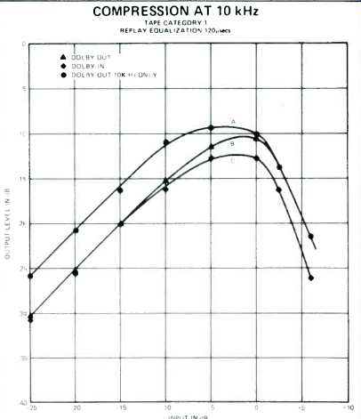
Fig. 7--Dolby B System transfer characteristics.
If compression effects described above are to be avoided using conventional tapes and a Dolby stretcher, the recording level must be reduced. This, in turn, reduces the replay level and decreases the basic signal-to-noise ratio which, of course, reduces the effective improvement achieved by the use of the Dolby.
Another effect, which can easily be avoided with the self-contained recorder, but is a little more difficult to establish control over with pre-recorded cassettes using the B Dolby characteristic, is the effect generated when the recorded bandwidth is greater than that which can be reproduced. Most recording systems are capable of recording to shorter wavelengths than the replay channel of the recorder can satisfactorily reproduce; the limitation being the replay head gap length. If a wide band signal is received by the recorder such as that shown in Fig. 4, the lower high frequency levels; i.e., from 12 to 20 kHz, will be sensed by the Dolby and be preemphasized before recording. If now the recorder only reproduces up to 12 kHz, these signals will not be received by the Dolby circuit on replay. Therefore, the Dolby loop is not correctly closed and there is no corresponding reaction from the replay circuit to correct the level change generated in the recording mode. In a severe case, this tracking error results in a frequency response with a significant dip at low levels in frequencies around 5 kHz as shown in Fig. 8. The frequency responses shown in Fig. 8 are taken at 10 dB intervals with the top one at a level equivalent to maximum recording level. Responses B and D are taken with the recording bandwidth wide open and A and C were the controlled recording bandwidth. The mid-frequencies would not be significantly boosted during the recording process, but on replay the B Dolby HF gain reduces to its minimum because of the much reduced high frequency energy in the replay signal. A possible solution to this problem for the duplicator is to limit the bandwidth which activates the Dolby, during the recording of music cassettes, to about 10 kHz. With a cassette recorder, another solution is to design the recording amplifier to have the same bandwidth as the replay system.
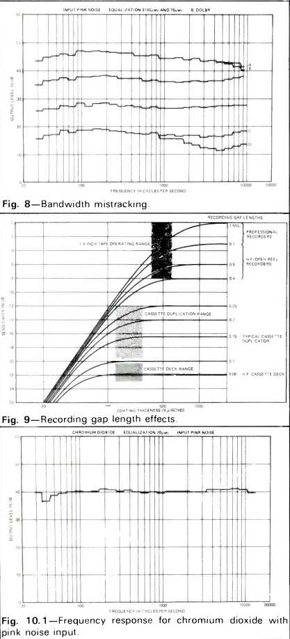
Fig. 8--Bandwidth mistracking.
Fig. 9--Recording gap length effects.
Fig. 10.1--Frequency response for chromium dioxide with pink noise input.
Recording Gap Length
The full presentation of the study into the gap-length/ coating thickness relationship will be published as a separate article. However, it is appropriate for the purposes of this article to publish the theoretical relationships shown in Fig. 9.
These have been verified experimentally. As can be seen with recording gaps which are shorter than the coating thickness, the performance of the tape/record head combination is not dependent on the coating thickness because they do not utilize the whole coating. Gaps which are significantly longer than the coating thickness record through the whole of the magnetic layer and, therefore, the sensitivity of the system at long wavelengths is coating thickness dependent.
Apart from the fact that a duplicator operates at speeds which are much higher than 1 7/8 ips, the principal difference between recording on a duplicator and a consumer cassette recorder lies in the dimension of the recording head gap.
Most duplicators use special record heads whose gaps are in the region of 150 microinches to 400 microinches long, whereas the consumer machines use dual purpose heads which have a gap whose dimensions are determined by the desired replay performance. On high fidelity machines intended to record and play frequencies up to 15 kHz, an 80 micro-inch or smaller gap is essential. Typical cassette tape coating thicknesses lie in the range from 120 microinches for C-120 product to 250 microinches for some C-60's.
The development of higher efficiency ferric oxide particles of the type used in MRX, tape gives the tape designer the freedom to optimize the coating thickness for overall performance on a duplicator at coating thicknesses considerably thinner than has been the former practice. This has several advantages:
1. The coating thickness can optimize to the biasing requirements at the short wavelengths without sacrificing distortion and output at the long wavelengths and this bias can be adjusted to be approximately the same as with conventional gamma ferric oxide tapes when using a typical duplicator record head. Because of the improvements in the oxide, the output available from the thinner coating is 4 dB greater than with high output low noise tapes at low frequencies and 8 dB at high frequencies.
2. The same coating thickness can be used for all configurations.
3. The thin coating of approximately 130 microinches does not sacrifice any performance when used in a blank cassette on a consumer machine.
Practical Systems
Two separate high fidelity systems have been used for tape evaluation and the parameters chosen for both systems are based on the study described and utilized consumer type cassette decks carefully adjusted to meet our requirements.
Most of the listening tests and demonstrations of recorded quality have been performed without the use of any noise reduction system; although some testing has been carried out to determine whether the data presented earlier is, in fact, important in relation to what is heard. The recordings used were made from very high quality 15 ips stereo masters and which have recorded signals at significant levels to 20 kHz.
There is little doubt that where the high frequency energy is present in the input signal, the variable frequency response generated by the B Dolby System is audibly worse than with the same tape and recorder used without the Dolby in circuit. Apart from this reason, the noise reduction system was not used because the objective of our study was to evaluate tapes under development; for this purpose it is better to compare tape performance with as little intrusion from electronics as possible.
The first system was designed for chromium dioxide and incorporated the new proposed replay equalization at 3180 microsecond bass curve and 70 microsecond treble curve.
Figures 10 and 11 respectively give the frequency response and the noise spectra of this system using Memorex chromium dioxide tape. As a matter of interest, the response is presented in the form generated by the noise/analyzer system and the more conventional presentation taken manually with sine wave signals. The dip in the response at 40 Hz is caused by the contour of the record/play head. The unweighted signal-to-noise ratio is 53 dB referred to 333 Hz at the level which gives 2% total harmonic distortion. At mid-frequencies, the slot noise is -65 dB. The second system used for the improved gamma ferric oxide MRX, used the standard replay system of 1590 microseconds bass curve and 120 microsecond HF curve. The response of this system is shown in Fig. 12; Fig. 13 shows the spectra of the bias and the system noise. The unweighted signal-to-noise ratio is 52.5 dB referred to 333 Hz and 2% total harmonic distortion and the slot noise is 71 dB at mid-frequencies. The excellent signal-to-noise ratio of the MRX, ferric oxide system is due to the 2 dB extra sensitivity of this tape at long wavelengths plus the capability of accepting 2 dB more recording drive without the bias noise having been deteriorated in comparison to low noise high output tapes. Thus, the unweighted signal-to-noise ratio is 4 dB better than one would obtain from standard ferric oxide particles. The slot noise at mid-frequency is 6 dB better than with chromium dioxide but because the 120 microsecond replay equalization was used for MRX, and the 70 microsecond for chromium dioxide, the final signal/noise ratios are approximately the same. However, MRX, exhibits less high frequency compression than chromium dioxide when the two tapes are equalized in these differing manners.
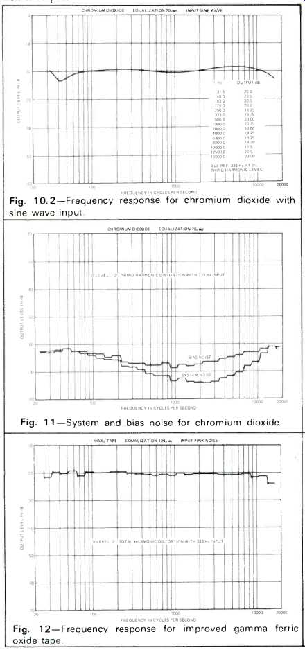
Fig. 10.2--Frequency response for chromium dioxide with sine wave input.
Fig. 11--System and bias noise for chromium dioxide.
Fig. 12--Frequency response for improved gamma ferric-oxide tape.
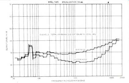
Fig. 13--System and bias noise for improved gamma ferric-oxide tape.
Acknowledgements
The author wishes to acknowledge the excellent experimental work carried out by Mr. Roy F. Nelson of Memorex Corporation, Audio/Video Group, without which this article would not have been possible. The curves for the recording head gap/coating thickness relationships were calculated by Mr. E. D. Daniel.
References
Acoustical Tests and Measurements, Davis; Published by Howard W. Sams and Company, Inc.; Page 60.
Chromium Dioxide Audio Cassette Tape, Jordan, Kerr and Dickens; Journal of the Audio Engineering Society, January/February 1972.
==========
(adapted from Audio magazine, Oct. 1973)
Also see:
Cassette Tape Recording Bias (Nov. 1973)
Dolby B-Type Noise Reduction System (Sept. 1973)
The 8-Track/Cassette Cold War Gets Warmer (Jan. 1970)
= = = =