by DICK CRAWFORD
INTEGRATED CIRCUITS are fast becoming an electronic way of life. But there are certain requirements that integrated circuits should fill before they can be adopted in the best of hi-fi equipment:
1. Low distortion.
2. Low noise.
3. Adequate output level.
4. Output short-circuit protection.
5. Input overdrive protection.
Long and sometimes sad experience in the misuse of audio equipment leads me to the last two requirements.
How do recent linear integrated circuits measure up to these criteria? Very well indeed, for low-level and preamplifier applications. The author has had the opportunity to use quite a few linear integrated circuits, and the experience has prompted the design of this tone-control circuit The Baxendall or feedback type of tone control circuit was chosen. Since it is a feedback type of circuit it achieves the tone-control action by varying the amount of negative feedback at different frequencies. This generally results in lower distortion than the more conventional tone control, where control is achieved by varying the loss at different frequencies. Secondly, it uses linear potentiometers, which implies better tracking between the two channels of a stereo amplifier insofar as the tone controls are concerned. Conventional tone controls use audio or logarithmic potentiometers, which, due to the way they are made, typically do not track as well as linear potentiometers.
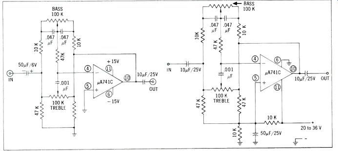
Fig. 1--Schematic of IC tone-control circuit. For stereo use, two identical
units are required. The numbers in circles indicate pin numbers. Both 100-k
pots are linear.
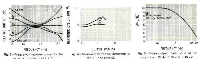
Fig. 2--Schematic of the tone control rearranged to work with a single positive
supply voltage. This requires two additional resistors and one extra capacitor,
but eliminates need for the negative supply.
Fig. 3-Frequency-response curves for the tone-control circuit of Fig. 1.
Fig. 4-Measured harmonic distortion of the IC tone control.
Fig. 5-Noise output. Total noise of the circuit from 20 Hz to 20 kHz is 10 µV.
A disadvantage of the Baxendall circuit is its relatively low input impedance. Another disadvantage is its nominally low gain, namely one. A third disadvantage of the typical circuit is that it requires a center tapped potentiometer, but this drawback has been eliminated in this design (see Fig. 1). The performance is very good. From Fig. 3 we note that nearly 20 dB of control are available at 20 Hz and 20 kHz. Control is proportional to rotation. The response is within plus or minus one dB from 20 Hz to 20 kHz when the controls are set in mid-position.
Distortion is exceptionally low, never rising to more than .025 percent for any output level up to 5 volts rms at 1 kHz (Fig. 3) . Actually the circuit will put out more than that; I just didn't test it any higher.
The circuit as shown in Fig. 1 operates from positive and negative supply voltages, as is typical with operational amplifiers (op amps) . In this mode its output will have less than one volt d.c. offset. Figure 2 shows an alternative arrangement for connections involving a single 20-to 36-volt supply. In this latter configuration the circuit must be a.c. coupled, as shown.
Figure 5 shows the noise characteristics of the tone control. This includes the impedance effects of the tone-control network, the noise characteristics of the integrated circuit itself, and a 600-ohm source impedance. As can be seen the noise is relatively constant at 100 nano-volts per square root Hertz up to about 1 kHz, where it begins dropping. This is probably due to the current noise of the IC and the impedance variation of the tone control with frequency.
At any rate, the noise including hum is very low, being only 10 microvolts from 20 Hz to 20 kHz. If the signal is 1 volt rms, then the signal-to-noise ratio is 100 dB. This unit could be built in a box as an adjunct to a present amplifier, but it is really intended as part of the control circuitry of a stereo amplifier or preamplifier.
The particular integrated circuit chosen is the Fairchild µA741C, of which the author is fond, but I, presume that others could be used. The National LM 307, Motorola 1539G, RCA CA-3029, and Signetics N-5709 are suggestions. Not all of these have internal frequency compensation, so you had best refer to the data sheets of those devices for recommended unity-gain compensation networks before plugging them in. The Fairchild distributors (try your phone book) are my source for the µA741C's. Amelco and Texas Instruments are also reputedly making the µA741C. The circuit diagram of the µA741C or as close to it as a user is apt to get, is shown in Fig. 6. A veritable forest of transistors, all on a silicon chip less than 1/16 in. square.
A perfect amplifier has been described as a straight wire with gain, his tone-control circuit has no mid-frequency gain, little noise, and almost no distortion. Perhaps it could be called a flexible wire.
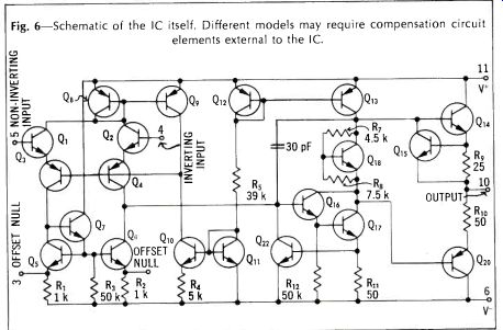
Fig. 6-Schematic of the IC itself. Different models may require compensation
circuit elements external to the IC.
--------------
(Audio magazine, 11/1969)
Also see:
Acoustical Matching of Sound Systems and Auditoriums
Behind the Scenes: A Professional Viewpoint
= = = =