PASSIVE CROSSOVER NETWORKS--FOR BI-AMPLIFIER SYSTEMS
Attributes of passive speaker crossover networks vs. electronic crossovers.
By BLAINE B. KUIST
ELECTRONIC CROSSOVERS are getting the spot-light in a resurgence of interest in bi- and tri-amplification (high, intermediate, and low frequencies split ahead of the power amplifiers) . A lot of hi-fi buffs might be interested in an alternative that is simpler to build (2 hours), not too costly ($50 for two channels with one crossover point), high in reliability with few components and top performance.
The alternative is the old workhorse-passive L-C filter networks.
An article about Electronic Crossovers , intrigued me with the potential of improved sound with bi-amplification. My hi-fi fever set in last spring after looking for a starter outfit with my teenage son. Casual looking and listening led to growing interest.
I wondered why a treble speaker like the Altec-Lansing 802-D driver and 511-B horn couldn't be teamed with a good 15-in. speaker, thus covering the whole audio range with just one crossover. By now I had eagerly waded through some of the good handbooks for hi-fi hobbyists, such as "Speaker Enclosures," by A. Badmaieff & Don Davis,2 and "Hi-Fi Projects for Hobbyists, by Leonard Feldman .3 From current literature from manufacturers like Sony, Bozak, C/M Labs, and Pioneer, a tailored design (for a selected crossover frequency and cutoff slope) of an electronic crossover appeared to be a tough project for a beginner to tackle.
1 C. G. McProud, "How to Build a 3-Channel Electronic Crossover, AUDIO, February 1968, p. 19.
Fortunately, I talked to a professional audio engineer about my interests. His reaction was, "Why not use high- and low-pass filters?" The key idea was to feed the filters from the pre-amplifier, matching the 600-ohm output impedance of the pre-amplifier with a 600-ohm input impedance of the filter. The 600-ohm output impedance of the filter was also matched and terminated by a 600-ohm resistor (in parallel with the 100-k ohm input impedance of the power amplifier). Thus the filter was matched at the input and output with 600-ohm constant impedances.
Settling on Filters
This sounded simple enough until I tried to find the filters. A search of electronic catalogs, stores, and magazines indicated filters were readily available with 18 dB/octave cutoff slope of the constant-k type but would have to be special-ordered for the 12-dB slope which was desired. Perhaps these are available from some professional audio equipment suppliers but my hurried searches failed to turn them up.
So it was back to the "do-it-yourself" method which didn't disappoint me, really. AUDIO'S articles on "Professional Audio Controls"4 had had a reference to Howard Tremaine's comprehensive handbook on Passive Audio Network Design. [5]
This had the practicalities of filter design and construction spelled out.
Again with simplicity in mind, I focused on parallel high- and low-pass L-C filters involving the familiar networks of conventional speaker crossovers except being designed for 600 ohms instead of the usual 4-, 8-, or 16-ohm speaker voice-coil circuits.
The filter networks selected and built are described as follows: Parallel, m-derived m = 0.6 for constant impedance over 85 percent of transmission band Impedance in and out: 600 Ohms Crossover frequency: 500 Hz Attenuation at crossover: 3 dB Slope of attenuation: 12 dB/octave The component values are derived from these formulas:
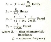
Where R. = filter characteristic impedance
f = crossover frequency
In rounding up material to build the filters, we found the capacitors were readily available but the inductances were another matter.
With values of 191 and 305 mH needed, air-core coils were out of the question because of large size and hence large resistance. Little usable information seems to be available for constructing iron-core inductors so it was back to the catalogs. Coils with desired characteristics were rarely listed and hard to find.
3. Alexis Badmaieff and Don Davis, Speaker Enclosures," Sams, 1st Ed., 3rd ptg., 1967.
4. Leonard Feldman, "Hi-Fi Projects for Hobbyists," Sams, 1st Ed., 3rd ptg., Nov. 1966.
5. A. C. Davis & Don Davis, "Professional Audio Controls," AUDIO, Feb., Mar., May, 1967.
6. Howard M. Tremaine, "Passive Audio Network Design, Sams, 1st ptg., Feb. 1969.
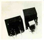
Fig.1--The passive networks are assembled in metal boxes, and connected ahead
of the power amplifiers-one for the highs, and one for the lows.
However, the United Transformer Company catalogs listed coils that covered the audio-frequency range with Q's of the order of 10 to 30 at the 500-Hz crossover point.
For the first pair of coils, the HVC Variductors were tried because they were adjustable and available at a nearby electronic store. The coils were finally set reasonably close to the desired values but they were sensitive to set, although once set, they held their settings and worked well.
For the second pair of coils, the MQA fixed inductances were chosen.
-------------------
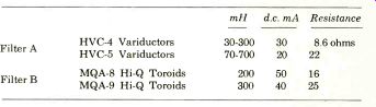
These high "Q" toroids with inductances of 200 and 300 mH ± 1 percent, the numbers closest to those desired without a special order. This compromise on inductance from the desired 191 and 305 mH was not significant.
A description of the coils used follows:
-------------
Filter A Filter B
HVC-4 Variductors HVC-5 Variductors MQA-8 Hi-Q Toroids MQA-9 Hi-Q Toroids mH d.c. mA Resistance 30-300 30 8.6 ohms 70-700 20 22 200 50 16 300 40 25
-------------------
Typical "Q" curves for the metal-core coils rise to a peak then fall off after the saturation point of metal cores is reached. The peak Q (about 160) for the MQA coils occurs at about 5 kHz. At the crossover of 500 Hz the Q is about 40. At 20 kHz, Q is about 25 and at 20 Hz it is in the range of only 1 to 2.
The HVC coils being adjustable, the peak Q falls somewhere in the lower half of the audio range depending on the setting. At 500 Hz the Q is in the range from 5-15.
Although the MQA coil had in general the higher Q characteristics, there was no audible difference in performance.
Filters Assembled
With the coils in hand, the remaining parts were really available and the assembly went fast. All the parts were mounted on a plastic board fastened to the cover of a 4" x 5" x 3" steel box. Steel was used for shielding although this was found later to be unessential.
The assembled filters are shown in the Fig. 1 with the back of the cover and the board exposed to show wiring and components for one low- and high-pass filter combination.
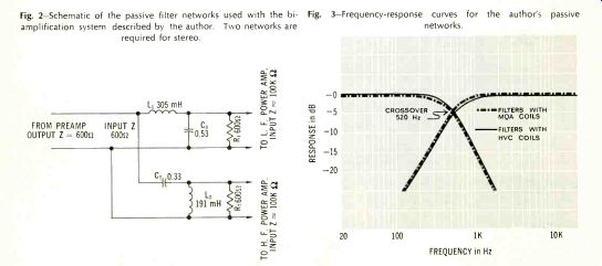
Fig. 2--Schematic of the passive filter networks used with the bi amplification
system described by the author. Two networks are required for stereo.
Fig. 3-Frequency-response curves for the author's networks.
Response vs. frequency curves were run with an audio generator and a VTVM with the results shown in Fig. 3. The 520-Hz crossover point was close enough to the 500-Hz goal.
The crossover point was down 3.5 dB from the bass plateau and 4.0 from the treble, vs. the goal of 3.0. Theoretically, the total sound pressure level should then suffer a bit of a drop in the crossover region.
-----------------
TABLE I COMPARISON OF CROSSOVER ALTERNATIVES
---------
PASSIVE
Ahead of Amplifiers
ELECTRONIC
Ahead of Amplifiers
CONVENTIONAL
After Amplifiers
--------------
Bass speaker: damping and transient response Permits performance to full damping ability of amps.
same as passive Reduces woofer response by resistance and reactive impedance between ampl. and speakers.
Amplifier performance IM distortion minimized by high and low frequencies going through separate amplifiers. Greater dynamic range due to separate amplifiers.
same as passive IM distortion due to hi and low going through same amplifier. Dynamic range limited because power peaks for hi and low are additive.
Speaker distortion Minimized None due to crossover frequency shifting.
same as passive Distortion added. Crossover frequency and phasing of hi and lows shift with actual impedance of speaker causing unwanted frequencies going into wrong speakers and dulling of stereo image.
Crossover network distortion <0.1% THD <0.1%o THD Coml. units 0.1 to 0.5% Can be <0.1% THD with top quality components.
Reliability Good-few components.
Has several fold more components with more chance for problems.
Good-few components.
Costs Crossover: parts $50 for 2
Ampl: Requires amplifier for each speaker.
Crossover: parts $50 for 2, ready-built $100-$200 for 2.
Ampl: Requires amplifier for each speaker.
Crossover: lowest cost
Ampl: only 1 stereo required.
Time to build by amateur 2 hrs. for 2 20-40 hours. for 2 2 hrs. if coils ready built; add time if coils to be wound.
Insertion loss (-) or gain (+)
3.5 dB 0 to +3 dB typical Some types,-6 dB Depends on quality (hi Q) of particular coils used.-0.1 to-2 dB typical.
-------
-------
Practically, this slight dip could not be measured in the total output from the speakers (audio generator input and microphone pickup) and certainly could not be detected by ear. The insertion loss was 3.6 to 3.2 dB (20 Hz and 20 kHz respectively).
As the textbooks state, distortion for the passive filter network should be practically nil. This was checked through the courtesy of a manufacturer's amplifier clinic and proved to be so. The filters were used between a Dynakit PAT-4 preamplifier and two Dynakit 120 amplifiers.
The THD was measured at 2 volts output, which would fully load the amplifiers when feeding 16-ohm speakers. No difference could be read in the THD with and without the filters in the output.
In my setup, the amplifiers were fed into the Altec-Lansing treble horns mentioned earlier and Klipschhorn bass corner horns. The defenders of the conventional crossover have pointed out that the electronic crossover (or filter) ahead of the amplifiers adds little or nothing to the damping of the bass speaker which is horn loaded like the Klipsch. Theoretically, this might be right. I have not had the opportunity yet to check this by A-B tests of conventional crossovers vs. filters with the horn-loaded speakers.
Probably the differences are less prominent than with direct-radiating speakers. All I can say at this point is that the sound from the horns with the filters ahead of the amplifiers is superb.
If you have been following the interesting articles and letters to the editor in Audio Magazine for the last year and a half on this subject, you are pretty well posted on the pros and cons of electronic crossovers vs. conventional crossovers after the amplifiers.
This article presents another alternative, the passive filter networks ahead of the amplifiers. Comparing filters with electronic crossovers, it appears that there is a lot to be said for the filters, especially for the audiophile who wants to build the device himself with minimum time and cost. Advantages and disadvantages of the three alternatives are listed in Table I. The debates continue on whether the sound . is significantly better (and worth the cost) with the crossover ahead of the amplifiers. To anyone who has listened to an A-B test with direct radiating speakers, there is no doubt about the result being audibly better with crossovers ahead of the amplifiers. And for the audio buff who is determined to get the best in sound, an easy, economical, and reliable way to it is with the passive filters.
--------------
(Audio magazine, 11/1969)
Also see:
Behind the Scenes: A Professional Viewpoint
= = = =