by Daniel Queen
RECENT INTEREST in equalization of sound reinforcement systems has resulted in many terms being tossed about. Included have been broadband equalization, narrow-band equalization, notch-filters, one-third octaves, direct-to-reverberant ratio, etc.
There is much dispute now on the relative merits and effects of these various measures. Before a sound contractor decides on a particular measure, he should know exactly what that measure is capable of doing but more importantly, what it is not capable of doing.
The technology of using notch filters for room equalization was popularized by C. Paul Boner after studying church reinforcement systems which appeared to exhibit several sharp response modes. When these modes were removed by means of filters only a few Hertz wide, the capability of the system to provide gain before howlback was enhanced. Boner's studies showed that many of the rooms with which he worked could be improved using as many as fifty or sixty such filters. It should be noted that Boner advocated the use of such filters only after the system had been built with high quality components and after the system was broadband equalized.
Herein lies the rub: The difference between broadband equalization and notch filtering is sometimes confused. Broadband equalization is accomplished after making measurements of the room response, usually by means of third-octave filters, then correcting the response in each of these third-octave bands. The usual approach is to make the third-octave measurements at various points in the room. A noise source feeds the amplifier or microphone. The response at the various locations is averaged, then estimates are made about which are the most significant factors to be corrected.
The equalization filters used to correct the system in this process are no, narrower than one-third octave. In the vicinity of I kHz such a filter is 200 Hz wide. In contrast, narrow band equalization is achieved by increasing the gain of the sound reinforcement system until either ringing or howlback occurs. A notch filter is then inserted at the frequency of the ringing or howlback. Such a filter is typically about 5 Hz wide at its half-power points.
Sources of Perturbations
Deviations from flatness in a sound reinforcement system, when in an actual room, are caused by characteristics of the room itself, of the electroacoustic components, and of the interaction between the room and the electro-acoustic components.
Every room acts somewhat like an organ pipe. For each major dimension, resonance frequencies occur at the frequency where the dimension is one-half wave length and at integral multiples thereof. Thus, a room 30 feet in length will have resonances at 15 Hz, 30 Hz, 45 Hz, etc. The other major dimensions will generate resonances at similar harmonic intervals. One can see that, as frequency increases, more of these resonance modes will occur (the "mode-density" will increase). In fact, in most rooms, the mode-density above 250 Hz is such that modes are separated by no more than 5 Hz, their Q is approximately equal, and they are distributed evenly about the room, resulting in an essential flat amplitude vs. frequency response when exited. Only when rooms are unusually shaped or have a very, uneven distribution of absorbing materials, can one expect the amplitude of any mode to exceed the average of all the modes--particularly within third-octave bands.
Thus, except at very low frequencies, the room itself contributes little to non-flatness due to individual modes. Instead the room characteristically shows greater absorption and therefore amplitude roll-off at the extreme ends of the band.
The roll-off at the low end is mainly due to vibration of walls, causing sound to leave the room, and at the high end by the absorption of materials on the walls or in the room.
The effect of such absorption is usually spread over a wide band, looking much like the effect of tone controls (Fig. 1).
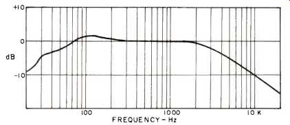
Fig. 1--The broadband steady-state response of a typical meeting hall (averaged
over tenth octaves).
The equalization for it is broadband. However, an unusual effect is caused when a loudspeaker or a microphone is inserted into a room. If the loudspeaker is spaced away from a reflecting surface, it will produce, a series of peaks and dips associated with the distance from the surface, as shown in Fig. 2. These peaks and dips go to a minimum when the speaker is actually put into the wall. Usually these peaks and dips are well inside the pass band of a third-octave filter and must be equalized by means of narrow-band filters.
A similar effect occurs with a microphone, the nearest reflecting surface being the floor or a lectern table top.
Similarly the effect is minimized by moving the microphone close to or into the table top or if possible, close to the floor.
The effect of floor reflections can be minimized by use of directional microphones provided they are truly directional in all planes (as we shall discuss later.)
Amplifiers and Signal Processing Circuitry
The amplifiers and signal processing circuitry in a sound reinforcement system generally can be depended upon to be free of amplitude perturbations. However, care must be taken that, due to unusual tone control circuitry, etc., excessive phase shifts that could throw a system into positive feedback do not occur.
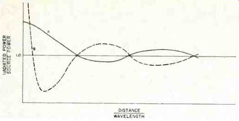
Fig. 2--The effect of locating a loudspeaker near a reflecting surface. Curve
A is for a hard surface; curve B for an absorbent surface. For any fixed distance,
the curves represent the amplitude-frequency characteristic of the radiation.
The sensitivity-frequency characteristic of a microphone follows similar curves.
Loudspeakers and Microphones
The characteristics most commonly specified for microphones and loudspeakers for sound reinforcement systems are frequency response and directivity. These should be the characteristics which would most affect the susceptibility of the system to howl-back. The freer of peaks the response is, the less the chance of howl-back at one of those peaks. The more directive the transducers can be, then the more direct sound from the talker and to the listener will be produced at a given gain setting of the system. Thus it would seem that a microphone specified with a flat response and with good directivity would be the best microphone to choose for the system. Unfortunately, the frequency response given with the microphone is usually the zero incidence response in a free field, that is, a non-reflective environment. If it is a directional microphone, the response at one or two other angles may be plotted. Loudspeakers are specified with the on-axis response supplemented by a polar plot of the loudspeaker at 4 or 5 frequencies. The polar plots are usually shown in two planes around the loudspeaker. This would be adequate to tell the performance if actual rooms had only the two planes measured in these response plots. Actual rooms, however, must be analyzed in three dimensions, so no single incidence or plot in a few discrete planes reveals the full performance of the transducer.
Incident and Reflected Sound
The problem can be better appreciated through an examination of the different sound fields that exist in an actual room. The fields are defined by time and direction: 1. The sound that goes directly from the sound source to the receiver; 2. The sound that goes from the sound source to the receiver with one or two reflections, and 3. The sound that goes from the sound source to the receiver with an almost infinite number of reflections. These are called, respectively, the direct field, the early reflections, and the reverberant field (Fig. 3). In most of the literature the early reflections and the reverberant field are differentiated on the basis of the sensitivity of human hearing to the relative time of arrival of sounds. If the reflected sound is heard less than 65 milliseconds after the direct sound, the human hearing process fuses it with the direct sound. After 65 milliseconds the human hearing process hears it as an echo or a discrete sound.
Speech intelligibility is usually found in the direct sound and the early reflections. Recent studies have shown that a low ratio of direct-early to reverberant sound acts similarly to a low signal-to-noise ratio in reducing intelligibility. Contrariwise, musical quality is found in all fields. Thus a non reverberant room, which sounds very good for speech, would sound dead for music.
One of the reasons for this lies in the transient characteristics of a room. The direct sound flows from the sound source to the receiver at the propagation velocity of sound in air, while dropping in amplitude 6 dB for each doubling of distance. The early reflections travel similarly, although the distance, naturally, is greater. However, the reverberant field acts like a capacitor being charged. In fact, its rate of build up is very similar to the exponential charging rate of a capacitor.
Thus the rapid transient sounds of speech will not excite the reverberant field as much as the continuous sounds of music. A room, which in combination with a loudspeaker, is found to have a direct-early to reverberant energy ratio at the center seats of 0 dB, when measured by steady state methods, may actually have a 10 dB direct-early to reverberant energy ratio for speech.
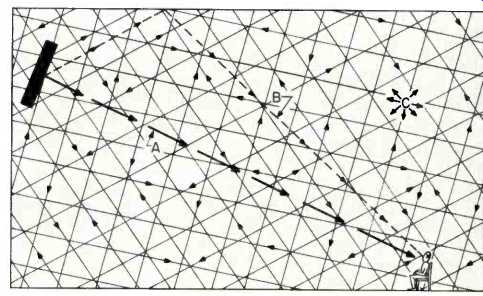
Fig. 3--The sound fields excited in a room by a loudspeaker. A is the direct
sound; B, the early reflections, and C, the reverberant field.
Therefore, for speech intelligibility, one would be most concerned with the response of a loudspeaker and microphone in the direction that would be normally between the sound source and the receiver. This would seem in concurrence with the specification of the microphones and loudspeakers in terms of frequency response at zero incidence.
The Acoustic Feedback Loop
However, good response in the direct field is meaningless if one cannot turn the gain up without getting howlback. Howlback occurs because, in the feedback loop shown in Fig. 4, the gain between the output of the loudspeaker and the input of the microphone becomes greater than one and in-phase at a particular frequency. If the phase and amplitude characteristics show some non-linearities, which they usually do, the system can ring without howling. It is obvious that this howlback causing path is not in the on-axis direction, since a microphone is usually not placed directly in front of and facing the loudspeaker.
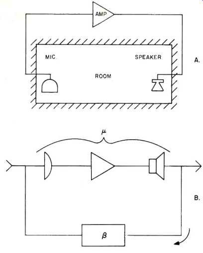
Fig. 4--Sound reinforcement system, A, and its electrical analog, B.
Direct-To-Reverberant Ratio
As shown in Fig. 3, the amplitude in the direct field drops in half with every doubling of distance. In contrast, when the sound source is continuous, that is steady state, the amplitude of the reverberant field is almost the same throughout the room (although peculiar shapes and unusual reflecting or absorbing surfaces can cause some variations). Thus, as one moves away from the sound source the amplitude of the direct field approaches that of the reverberant field (Fig. 5). Where the microphone and loudspeaker are completely directional, so that the loudspeaker radiates only in a forward direction and the microphone gathers only from its front, then, if the microphone and loudspeaker are not facing each other, the only path between the microphone and loudspeaker would be the reverberant field. It would be only the peaks in the reverberant response of the room that would cause howlback problems (provided we selected microphones and loudspeakers with flat response). Yet, we have shown that above about 250 Hz the room should be essentially flat (except for broadband variations). Why then is it still found necessary to use narrow-band filters? The answer can be seen by examination of the off-axis characteristics of the transducers.
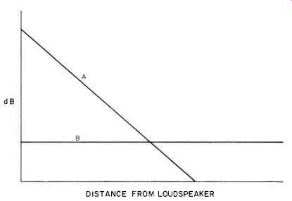
Fig. 5--The relation of sound fields to distance from the loudspeaker; A,
the 6 dB loss per doubling of distance for the direct sound, and B, the reverberant
field.
Random Incidence Versus Axial Response of Microphones
The directional patterns are commonly designed into microphones as shown in Fig. 6. Although the figure shows them in two dimensions, they actually exist in three dimensions.
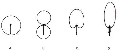
Fig. 6--Ideal microphone directivity patterns: A, non-directional; B, bidirectional;
C, cardioid, and D, super-cardioid.
The omnidirectional pattern is ideally a sphere with the microphone at its center; the cardioid pattern roughly the shape of a cherry with the microphone at the stem; the bi-directional pattern, two spheres end to end with the microphone between them; and the ultra cardioid pattern roughly the shape of a cucumber with the stem projecting behind the diaphragm. Ideally, these patterns are the same at all frequencies. However, just as there are no point sources in the real world, there are no ideal patterns in actual microphones.
There are two ways to measure the response of a microphone. One is the free-field response, in which a source closely simulating a point-source is placed at a fixed angle to the microphone in a room free of reflections at a distance many times the largest dimension of the microphone.
Using this method, the actual frequency-response is measured at various angles to the microphone. Thus its directivity pattern can be plotted.
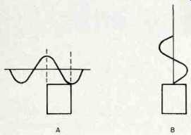
Fig. 7--A, a wave striking a microphone diaphragm with parallel (90°) incidence;
B, a wave striking the same diaphragm with perpendicular (0°) incidence. In
case A, simplified for illustration, the diaphragm sees equal negative and
positive pressure, causing a null. However, in case B, the perpendicular incidence,
the diaphragm sees only the wave front, so no null occurs at any wavelength.
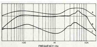
Fig. 8--Sensitivity-frequency characteristics of a cardioid microphone. A,
random noise incidence; B, on-axis (0°) incidence, and C, rear axis (180°)
incidence.
The second method is the random-incidence (sometimes called pressure) response. In this method the microphone is placed in a highly reverberant room at a point where it will receive very little direct sound from a source but will receive an infinite number of waves from an infinite number of angles to it. Using the random-incidence method, all the free-field responses from every angle are averaged. The difference in sensitivity level of a microphone between perpendicular incidence and random incidence is a measure of the perpendicular incidence directivity-factor of that microphone. It is obvious that a true omnidirectional microphone would have a directivity factor of 1, whereas the directivity factor of an ultra-cardioid microphone would be higher than that of the other types. However, for a microphone to respond to vibrations in the air, it must have a large enough diaphragm to absorb sufficient energy to create an electrical signal sufficiently above the thermal noise of the microphone structure to result in a useful signal-to-noise ratio.
Therefore, most omnidirectional microphones have diaphragms with diameters in the order of an inch. Figure 7 shows that when a wave having a length close to that of the diameter of the diaphragm falls on the front of the diaphragm it will respond the same as a wave having a length much larger than the diaphragm. However, if the wave comes in parallel to the diaphragm, it will tend to cancel itself out as it passes over the diaphragm. Thus, a microphone which is designed to be flat on-axis actually must have a hole in its response off-axis. If, on the other hand, it is designed to be flat in its random-incidence response, it will have a peak somewhere around 5 kHz on-axis. In one case, the microphone can be seen to have a non-flat response in the reverberant field, aggravating the howlback; in the other, the direct-early sound with be peaked and raspy.
Figure 8 shows the response of a typical, high-quality cardioid microphone. The on-axis response is shown to be very flat. The off-axis response at 180° shows some variations including peaks near 200 Hz. It is this off-axis characteristic which distorts the response in the reverberant field. It is possible, in fact, that the peak in the off-axis response of a directional microphone can be sufficient to put the loudspeaker into the direct field of the microphone, that is at that frequency, the signal directly from the loudspeaker can be louder than the signal that flows to the microphone from the loudspeaker through the reverberant field.
Loudspeakers
The directivity patterns of loudspeakers are even more subject to this type of inconsistency in directional pattern.
Because loudspeakers need radiating surfaces which are large compared to the shorter wave-lengths they must radiate, their radiation can be made consistent only by approximate methods. Thus every loudspeaker, even if its individual elements are nearly ideal, has many finite lobes as shown in Fig. 9.
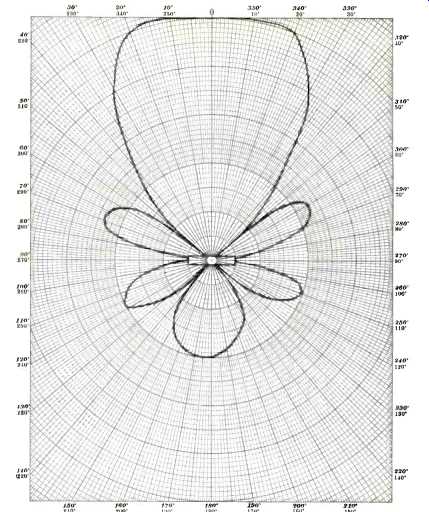
Fig. 9--Polar plot of loudspeaker radiation at one frequency on one plane.
Equalization for Defects
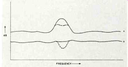
Fig. 10--Effect of a 10 Hz wide notch filter on A, reverberant field, and
B, direct-early sound field.
The peaks, which cause howlback at a lower gain than could be accomplished with ideal transducers, can be reduced with narrow band filters-but care must be used when doing so. Figure 10 shows the effect of a 10 Hz filter on a peak 30 Hz wide. Since the filter is placed in the signal processing circuitry of the sound system it also affects the direct sound that is delivered to the listener. The audible effect of the 10 Hz filter is very small and would probably not change the sound heard by the listener. Figure 11 shows the result of adding additional filters to reduce the peak even more.
As these additional filters are added, a hole begins to develop in the direct field response causing deterioration in the quality of the sound at the listener. It is for this reason, among others, that acousticians strongly warn against beginning narrow band equalization until one has carefully chosen and carefully installed the best transducers.
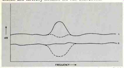
Fig. 11--Effect of additional filters on A, reverberant field, and B, direct-early
sound field.
Directivity Pattern Defects
As with microphone response, the response of loudspeakers can be measured in two ways. A test microphone may read the response from different angles to the loudspeaker in a free field. Similarly, the loudspeaker may be used to excite a reverberant room with a microphone placed so it picks up the reverberant field without receiving the direct field of the loudspeaker. The first method measures the free field response of the loudspeaker. The second measures the reverberant or power response of the loudspeaker. The power response is the characteristic that excites the reverberant field in an actual hall. Frequently, due to the lobes in the loudspeaker polar response or due to problems in the placement of the loudspeaker in the room, the power response of the speaker is very different from the direct field response. If, when measuring the response of a sound system preparatory to broadband equalization, the microphone is placed in the reverberant field of the loudspeaker and equalization is applied, the direct field of the loudspeaker may be severely distorted affecting the quality of the sound (Fig. 12).
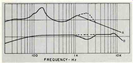
Fig. 12--Possible effect of equalization of the direct-early sound field (B)
on the reverberant field (A).
If, on the same loudspeaker, the microphone is placed close to the loudspeaker, in the direct field, then the reverberant field may be distorted to such a degree as to aggravate the howlback of the system (Fig. 13).
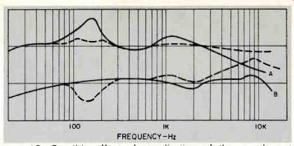
Fig. 13--Possible effect of equalization of the reverberant field (A) on the
direct-early sound field (B).
Effectiveness of Equalization
Thus, it can be seen that a system with severe transducer problems, that is, a substantial difference between the free field and reverberant field-responses of the transducers cannot successfully be equalized unless that equalization can be applied separately to the reverberant and direct fields--a condition which is rarely practical and is difficult to achieve.
To produce a system capable of high gain before howlback, the sound system designer must first obtain representative off-axis response curves for his transducers and compare these with the reverberant field and with the on-axis response. He must be sure that the combination of microphone and loudspeakers he chooses will not cause severe peaking in the reverberant field.
Secondly, the designer must take care in the placement of his microphones and loudspeakers so that he does not cause peaking due to reflective surfaces. He may then proceed to broadband equalization.
Broadband equalization may be achieved by placing the system microphone in the direct field of the loudspeaker, that is, close enough to the loudspeaker so that it will be mainly direct sound that is measured. Third-octave or broader filters are then inserted to flatten the response curve. Note that because the high frequency response in the reverberant field usually falls off as in Fig. 1, flattening the response with a microphone in this field will cause high frequency emphasis in the direct field resulting in a raspy sibilant sound.
Having thus flattened the direct field of the sound system, the system gain should be increased until howlback occurs.
Narrow-band notch-filters are then inserted to reduce the susceptibility to howlback. Such filters should be inserted until they begin to reoccur around the same frequencies. At this point the designer should go back to the direct field and see that his broadband equalization has not been distorted by the insertion of excessive narrow-band filters.
Conclusion
Sound system equalization should only be used as a last step in the design of a sound system and should never be used when care has not been taken in the selection and placement of loudspeakers and microphones. For speech reinforcement an effort should be made to place the direct sound of the talker at the ears of the listener. To accomplish this, microphones and loudspeakers should be as directional as possible, provided their off-axis response is as uniform as their on-axis response. If this is achieved, the improvement in gain before howlback achievable with directional loudspeakers and microphones will be proportional to the directivity factors of the loudspeakers and microphones. Improvements of gain in excess of 20 dB over systems commonly in use can be achieved by proper selection and placement of loudspeakers and microphones. The next step, the process of equalization, can achieve additional gains in the order of 6 to 15 dB.
References
1. C. P. Boner and C. R. Boner, "A Procedure for Controlling Room-Ring Modes and Feedback Modes in Sound Systems with Narrow-Band Filters," J. Audio Eng. Soc., Vol. 13, No. 4 (1965).
2. C. P. Boner and R. E. Boner, "The Gain of a Sound System," J. Audio Eng. Soc., Vol. 17, No. 2 (1969).
(Audio magazine, Nov. 1972)
Also see:
Constructing A Room Equalizer (Sept. 1972)
Psychology of Sound Reproduction (June 1972)
= = = =