By Leonard Feldman
IN THE COURSE of testing and reviewing various high-fidelity products for AUDIO Magazine over the past several years I have, from time to time, had to review various electronic products which are offered to the consumer in kit form. I've watched as construction manuals of various manufacturers have become increasingly "easy to follow" and as recently as two years ago I would have stated positively that kit-building manuals had reached a level of perfection such that even an unschooled chimpanzee could, "in just two evenings of spare time," assemble a stereo receiver using only "simple tools such as a screwdriver, cutters, long-nose pliers and a low-wattage soldering iron." I would have taken this position, that is, until I got involved in offering a kit product to the general public myself! The kit product that I offered was, from my point of view, as uncomplicated as could be. There was only one printed circuit board to worry about, some 20 or so resistors and an equal number of capacitors, a few transistors and an IC, some coils, parts for a power supply, a single chassis plate for mounting everything, and a plastic cabinet. I wrote a detailed, 8 page construction manual, replete with "helpful hints," line drawings, check lists, step-by-step instructions and (for the more technical user) a schematic of the finished product. After all, I had the benefit of having read many "professional" kit-manuals in the course of my work and could borrow the tried-and-tested techniques of the best of them! I started to ship my kits with justifiable pride, offering to help "trouble shoot" any unsuccessful efforts for a flat $5.00 fee. Since then, I had the deflating opportunity to examine about 100 "unsuccessful efforts"--and I've rewritten the manual no less than three times! Now admittedly, in any true "cross section of the buying public" I knew I'd find a few weird interpretations-but some of the fiascos that were returned to us are worth describing, not so much for the amusement of the experienced kit-builder (though we'll admit that we very often were doubled up in laughter), but for the forewarning of the neophyte who is about to take "the plunge."
The Parts List versus Taking Your Chances
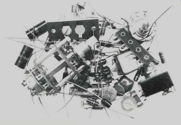
Most kit manuals start out by stressing the importance of opening up every package of parts and comparing the contents with the accompanying parts list. True, really elaborate kits usually subdivide the contents into individual envelopes or packages, but even the contents of one of these individual packages can resemble the panic-producing mélange shown in the photo of Fig. 1. If I were a kit builder embarking upon a first project, I'd rather skip the parts list check and take my chances on everything being there when I need it--still neatly packaged. I haven't run into a missing part for years, and if this misfortune should befall me in the future, I'll write to the manufacturer who would, I am sure, promptly make up the shortage. I find this approach much more practical than the piles of parts laid out on a workbench or table, especially since many electronic and hardware parts seem to be equipped with miniature motors which invariably propel them to the floor and don't shut off till the parts have rolled into a dark corner or under an immobile piece of furniture. The only caution I would offer is that you not throw away the shipping carton until all parts have been used up--as there may be one last envelope hidden amidst the packing material.

Fig. 1--HELP! Where do I begin?
Timing Estimates
Some kit producers insist upon providing the kit builder with an estimate of the time required to put together their product. Obviously, the intent is to sell kits by assuring the potential customer that he is not in for an endless task and I'm sure that in each such factory there is one (or more) technician who has the job of putting together a kit at breakneck speed so that the advertising agency can vociferously proclaim, ". . . build it in just one evening!" I've run into kits that would have to be transported to northern Greenland in the dead of winter to meet that requirement! Awake, kit manufacturers! DON'T start out by intimidating your potential customers.
They're going to try to equal or beat your time estimate and in doing so, you'll find yourself with more kits improperly wired or incomplete and your troubleshooting staff will soon be larger than your instruction manual writing staff! Awake, kit builder! The finished product you're trying to complete will probably give you good service for years to come-don't push it!

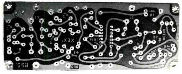
Fig. 2--The soldering side of a p.c. board.

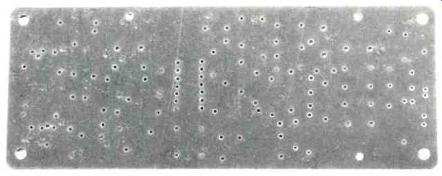
Fig. 3--The parts-insertion side of the same p.c. board.
Only a Few Simple Household Tools . . .
Many kit manuals approach the subject of a soldering iron apologetically.
The presumption, I suppose, is that most "households" are not normally equipped with a proper soldering iron for kit building. They therefore try to imply that a single 35 or 45 watt iron is all you need. Some even imply that a "soldering gun" can successfully be used for the multiple kinds of soldering required to put most kits together.
Nothing could be further from the truth. The very way in which a "gun" works will destroy the fragile copper patterns of a printed circuit board. Proper soldering of components on a printed circuit board involves the speedy but concentrated application of heat to the junction between the copper pattern and the component lead end emerging from the printed circuit board hole. A gun cools off quickly and reheats so slowly when the trigger is pulled that you end up holding the oversize "business end" of the gun against the printed circuit board for an agonizing length of time-often just long enough to separate the copper pattern from the base material of the board itself. We have found that a single, pencil-tip iron can do the entire soldering job for kits, providing you have more than one tip for it. Soldering of p.c. boards should be done using a pointed tip which flares to a diameter no greater than 1/8 inch. Heavier, chisel-shaped tips should be used for soldering directly-wired connections, such as wires to terminal strips, wires to socket terminals, etc.
If there is any "chassis grounding" to be done (soldering of electrolytic capacitor mounting tabs to chassis, etc.), an even larger tip may be required and, in some cases, a higher wattage iron may be required (65 to 90 watts). Before we leave the subject of soldering as related to printed circuits, we must tell you about one of the kits that was returned to us about a year ago.
Upon opening the carefully packed unit, we discovered, to our utter shock and disbelief, that the novice kit builder had inserted every single part in the p.c. board from the wrong side. That is, resistors, capacitors, transistors and IC's were all sitting nicely on the copper pattern side of the board. With all due respect to this kit-builder, we must say in his defense that he had somehow managed to solder every part from that side, by leaving a bit of exposed lead above each hole entry point. Needless to say, the board had to be scrapped.
We offered to replace the board and all associated parts at our cost, but I suspect the customer was too embarrassed to accept our offer and may, to this day, be carefully unsoldering each part and installing it from the correct side. The story may sound incredible, but when you stop to think about it, some manufacturers show board layouts as viewed from the copper side of the board, while others show layouts from the component side, with an X-ray view of the copper below, for purposes of "clarification." Make sure you understand the presentation in your kit manual before you start or it could happen to you. The really funny thing about this catastrophe is the fact that if we were dealing with passive parts alone (resistors, capacitors, coils, etc.), the board might actually have worked, but since there were three lead transistors and an IC involved, "bases" quickly became "collectors" in the mirror-image situation that resulted. Without belaboring the point, Figs. 2 and 3 show the P.C. board involved and parts are normally inserted with the Fig. 3 view facing you.
The list of tools usually recommended besides the controversial soldering iron consists of a screwdriver, cutting pliers, needle nose pliers (sometimes called "long nosed pliers"), and a ruler (for measuring prescribed wire lengths). It usually comes as somewhat of a shock to discover that most household screwdrivers have blades which are far too thick and broad to get into the slots of the miniature screws which usually accompany most kits. Often, Phillips head screws are supplied, and these usually stop the kit-builder dead in his tracks. I have found myself using no fewer than four different sizes and types of screwdrivers in building the average kit and having a variety of types and sizes on hand is a great convenience. I find, too, that the tool which I use more than any single screwdriver is one which is hardly ever mentioned-the "nut driver" (also popularly known by its trade name of Spin-Cite). This handy gadget (shown in Fig. 4) does for a nut what a screwdriver does for a screw. In mounting parts using machine screws and nuts, it is far easier to hold the screw stationary (with the blade of the screwdriver) while turning the nut with the nut driver than to rotate the screw with the screwdriver while trying to hold the nut stationary with oversize finger tips that never can get into the tight places required. A 1/4 inch and a 5/16 inch nut driver will cover most requirements, both dimensions referring to the distance between the parallel "flat" sides of the nut in question.

Fig. 4--A nutdriver used with a screwdriver helps assembly of hard-to-get-at
screws and nuts.
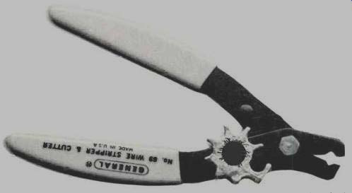
Although much of the work of kit building has been reduced to insertion of parts into p.c. boards, there still remain a goodly number of loose wires that are used to interconnect from one p.c. board to another or for inter wiring of such sections as power supply, power output stages in an audio amplifier, and other sections which do not lend themselves readily to p.c. board layout. What kit builder has not dreaded the familiar phrase, "strip N in. insulation from each end of a 12 in. piece of wire"? I must confess that I have been "stripping the ends" of wires with cutting pliers for nigh on to 20 years and every now and again, the wire in question becomes, successively, 11 5/8 in., 11 1/4 in., 10 7/8 in., 10 1/2 in., etc. as the sharp tips of the cutting pliers bite into the wire itself instead of just "stripping the insulation." A $1.98 solution to this problem is shown in Fig. 5. It's called (as you might have guessed) a wire stripper, and while there are varieties of this product that sell for several dollars, the type shown not only strips all sizes of wire you are likely to use (it's adjustable), but it doubles as a wire cutter too. About the only time I find I need cutting pliers now is for trimming the component leads of parts I have inserted into p.c. boards, where the pointed tip of the cutting pliers lets me get in close enough to cut off excess lead lengths so they don't "spill over" to adjacent copper patterns.

Fig. 5--A handy tool for stripping and cutting hook-up wire and reducing
kit building frustrations.
"Never Skip Ahead Of The Instructions ..."
Here, at last, is the one admonition given by kit-manual writers with which I must fully concur. I must confess that I too have been guilty of the cardinal sin of kit building-jumping ahead of the given order of step-by step instructions. Results have varied from the relatively mild punishment of having to unsolder several well soldered connections (to insert additional parts that were destined to go to the same terminal) all the way to having to unwire and remove a 12-lead power transformer because I just couldn't squeeze a fuseholder past its bulky mass to mount it on the back chassis flange. Let's face it, friends, despite fragmentary evidence to the contrary, most kit products have actually been assembled by their designers at some time or other and the printed assembly and wiring manuals are an outgrowth of that experience.
Now for Alignment and Test . . .
There is nothing quite so sad as completing a high fidelity component kit, checking all connections, turning it on, obtaining what seems like satisfactory performance and then proceeding to louse things up by second-guessing the alignment and test procedure. (Actually, I suppose an even sadder result is turning it on and having nothing happen at all. No, in the last analysis, I guess the most tragic event is turning it on and having something happen that isn't supposed to happen--like smoke pouring forth from the innards, or fuses blowing-or-well, let's not even pursue this any further ....)
"It Doesn't Look Factory Wired ... "
Unless you want to invest thousands of dollars in automatic wave-soldering units, automatic terminal connecting machines, riveting and eyeleting machines, solderless terminal connecting machines, tension wire-wrap machines, and the like, don't be surprised if your "end product" still looks a bit crude compared to the "factory wired" job. The somewhat archaic methods of wiring and assembling detailed in kit manuals persist not because kit-designers are oblivious to manufacturing progress, but rather in recognition of the limitations imposed by the needs of the "home builder" who is not expected to "capitalize" his kit building endeavors to the degree that a manufacturer might.
Happily, most kits today can be aligned with no test equipment at all. If that's the case, go to it, treating each successive step as if it were still part of the assembly and wiring process.
If a voltmeter or ohmmeter is required, don't proceed without one. If 'scopes and generators are required, don't try to bypass their use--even if it means taking your finished masterpiece to a friend who has such equipment. To salve your "pride of having done it yourself' (one of the main selling features of kits), perhaps he's a good enough friend to let you do the test and alignment, albeit with his equipment. If he insists on being the "engineer," that's still better than the thought of destroying your "one evening's work" (or one week's work, or one month's work) over a few minutes of checking and testing.
At the risk of further intimidating the faint-hearted (an outcome hardly initially planned for this otherwise helpful treatise), I'd like to conclude by quoting a paragraph from the section of my most recently acquired kit manual entitled:
"In Case of Difficulty"
After dealing with a host of troubleshooting hints, measurements that can be made and areas that can be visually checked and re-checked, the section concludes (as do I) with this immortal thought:
NOTE: In an extreme case, where you are unable to resolve a difficulty, refer to the service and warranty section of the "kit builders guide" and to the "factory repair service" information on page 143 of this manual.
(Audio magazine, Nov. 1972)
Also see:
= = = =