MANUFACTURER'S SPECIFICATIONS
FM SECTION. IHF Sensitivity: 2.0 uV. S/N: 70 dB. THD (Mono): 0.2%; (Stereo) 0.5%. I HF Selectivity: 70 dB. Capture Ratio: 1.0 dB. AM Suppression: 56 dB. Image Rejection: 70 dB. IF Rejection: 100 dB. Spurious Rejection: 90 dB. Frequency Response: 20 Hz to 15 kHz, 1 dB. Stereo Separation: Better than 38 dB at 400 Hz. 19 kHz, 38 kHz Rejection: 40 dB. SCA Suppression: 55 dB.
AM SECTION. IHF Sensitivity: 30 nV (external antenna). S/N: 50 dB at 50 mV/M. THD: 0.8%. Image Rejection: 50 dB. IF Rejection: 40 dB.
AMPLIFIER SECTION. Continuous Power Output: 60 watts/ channel, 8 ohm loads, 20Hz-20,000Hz; 70 watts/channel, at 1 kHz, 8 ohm loads, both channels driven. Rated THD: 0.2%. Rated IM: 0.2%. IHF Power Bandwidth: 15 Hz-35 kHz. Damping Factor: 50, at 8 ohms. Frequency Response: Phono: RIAA 1 dB; MIC: 100 Hz-10 kHz, +0,-3 dB; High Level Inputs: 10 Hz-70 kHz, +0, -3 dB. Input Sensitivity for Rated Output: Phono, 2 mV, Mic, 1.0 mV; High Level Inputs, 1 50 mV. Power Amp Input: 1 .0 V. Hum and Noise Level: (all referenced to rated input and rated output)
Phono, 72 dB; Mic, 65 dB; high level inputs, 90 dB. Power Amp Input: 110 dB. Tone Control Range: Bass: 10 dB @ 100 Hz; Treble: 10 dB @ 10 kHz. High Filter: 12 dB/octave above 9 kHz. Low Filter: 12 dB/octave below 50 Hz.
GENERAL SPECIFICATIONS. Power Consumption: 180 watts.
Dimensions: 18 1/4 in. w. x 6-3/16 in. h. x 14 3/4 in. d.
Weight: 33 ½ lbs.
Price: $499.50.
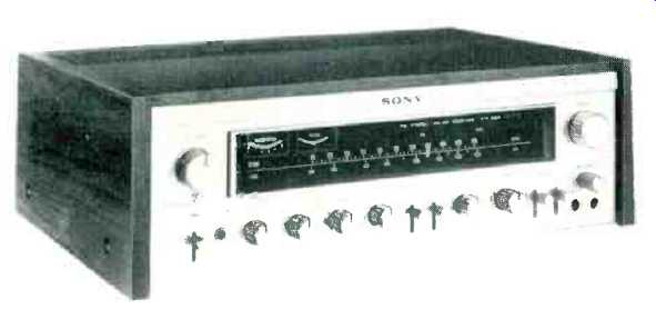
This top-of-the-line stereo receiver from Sony should help to maintain that company's well-earned reputation for elegance in design, both internally and visually. The massive gold colored panel, set back and framed by the side panels of the included walnut finished cabinet makes the STR-7065 eminently suitable for "instant use" on a shelf or table top. Removal of the cabinet discloses a complete metal enclosure rather than the exposed wiring of the chassis so commonly encountered with competitive units that come "complete with cabinet." Not only does this feature make sense for those of us who want to custom-mount a receiver behind a panel in existing furniture, but the extra internal cover provides shielding of low-level input circuits which might otherwise be subject to hum induction from other nearby components.
As for the front panel itself, the photo of the complete unit shows an orderly and carefully thought out arrangement of controls and switches surrounding a blacked-out dial scale area which, itself, is over 12 inches long. With power applied and selector switch set to all but radio functions, subdued green illumination of the dial area occurs and red program source indication appears at the upper portion of this area. When FM is selected, full dial illumination takes place, and both the signal-strength and center-of-channel tuning meters are brightly lit. In the AM mode, only the signal strength meter remains illuminated. At the left of the dial scale, a massive dual concentric knob/lever combination serves to adjust volume and balance, while a matching single knob at the extreme right is used for tuning stations in what is probably the smoothest flywheel action we have Yet encountered.
Along the lower portion of the panel are a lever-type power switch, stereo headphone jack, speaker selector switch (as many as three pairs of speaker systems can be connected to the STR-7065, with one or two pairs activated at any one time by this switch), dual concentric friction-loaded bass and treble controls, filter selector switch, mode switch (with full facilities for stereo, reverse, L+R, right or left only to both channels), program source selector and a microphone mixing and level control, located directly above a pair of microphone input jacks. In addition, there are lever-type switches for activating loudness and FM muting circuits and for selecting tape monitoring facilities for two separate tape inputs. In addition to their normal monitoring use, these tape inputs and outputs can be used for "dubbing" or printing from one tape recorder to the other, or vice versa, depending upon the setting of the program selector switch.
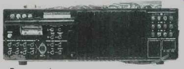
Fig. 1--Rear pear view.
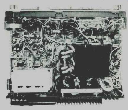
Fig. 2--Internal chassis view.
The rear panel, shown in Fig. 1, has the usual provisions for external program input sources plus the two sets of tape in-tape out jacks previously referred to. A standard DIN socket parallels the tape 1 inputs and outputs. Antenna terminals are provided for either 75 ohm or 300 ohm balanced antenna connections and there is a terminal for an external AM antenna as well, should the self-contained pivotable ferrite bar antenna prove to be inadequate for distant AM signal reception. Pre-amp out and main-amp input jacks are also included, which permit separate use of the preamplifier (to feed other power amplifiers-as in bi-amp or tri-amp electronic crossover arrangements) and power amplifier. The usual "jumpers" are absent from these jacks, since a separate slide switch is used to "make" or "break" this circuit interruption point. This thoughtful addition makes the circuit-interruption feature more useful, since the "preamp out" jacks are available for feeding programs to other amplifiers even when the amplifier of the STR-7065 is in use. Normally, the jumpers usually used to complete such circuits would prevent this additional usage.
Three sets of well-separated speaker terminals, two switched and one unswitched AC receptacle, and a separate ground terminal complete the back panel layout.
A view of the internal wiring of the chassis is shown in Fig. 2, and while at first glance the amount of harness wiring from module to module seems fairly great, we had no trouble identifying the various major circuits, which are well labeled for servicing, if required.
The sealed FM tuner section (front-end) uses junction FET's in both the r.f. and mixer stages, while the i.f. amplifier section uses permanently aligned ceramic filters and a high gain IC for limiting. The AM section has triple tuned ceramic filters as well, and a single IC circuit which includes an AGC circuit.
The amplifier section uses differential amplifiers and incorporates balanced positive and negative power supplies which permits direct coupled (output capacitorless) connection to the speaker terminals. The FM multiplex section includes an FET for high impedance isolation between the ratio detector and the input to a single IC stereo decoder circuit.
In all, the STR-7065 contains 5 IC's, 4 FET's, 49 bipolar transistors and 31 diodes--quite a handful of active devices for a single package!
Laboratory Measurements
FM performance measurements are shown in Fig. 3. IHF sensitivity measured 2.3 uV, which is not significantly worse than the 2.0 µV claimed by the manufacturer. Ultimate S/N reached 70 dB, as claimed, for all input signal strengths above about 80 V. Mono THD measured 0.18%-a bit better than the 0.2% claimed, while stereo THD measured just a bit over the claimed 0.5% at mid-band frequencies. 50 dB S/N was reached with a signal input of only 2.9 µ V. Muting action was positive and instantaneous, occurring at a signal input level of about 8 µV. In view of the excellent quieting characteristics observed, this parameter might better have been set at about 5 µV and, while no external adjustment is provided for the customer, potentiometer RT-201, which we located easily on the included schematic, could be trimmed to readjust the muting threshold if this is important to the user.
Stereo threshold occurs at an input of 4.5 µV, just exactly where we felt it should with a receiver of this quality, and the transition is smooth and positive. Stereo separation, shown in Fig. 4, reached 38 dB at mid-band, as claimed, falling off to about 28 dB at 50 Hz and about 20 dB at 10 kHz. Mono THD was below 0.5% at all frequencies from about 60 Hz to 7 kHz and barely reached 1.0% at 15 kHz. Stereo THD remained well below 1.0% from 50 Hz to over 2 kHz, above which "beats" between the internal 19 kHz and the test frequencies tended to produce high readings on our distortion analyzer.
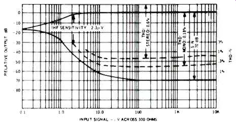
Fig. 3--FM performance characteristics.
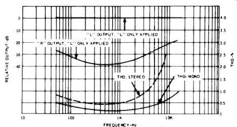
Fig. 4--Separation frequency.
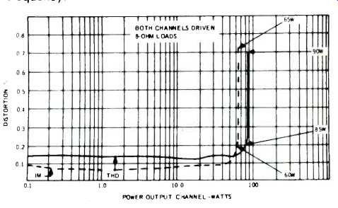
Fig. 5--Harmonic and IM distortion characteristics.
Amplifier Measurements
If the tuner section of the STR-7065 were categorized as basically meeting its excellent specifications, we'd have to rate the amplifier as one that exceeds its claims by far. As shown in Fig. 5, THD reached the manufacturer's rated (and very low) value of 0.2% at an incredible 85 watts per channel.
Remember, that Sony rates the amplifier at 70 watts mid-band, per channel and, even more conservatively, at 60 watts/ channel for all frequencies from 20 Hz to 20,000 Hz! At all power levels below 60 watts, THD measured well below 0.15%, while IM distortion measured under 0.1% for all power levels up to 45 watts, rising to the rated 0.2% at 60 watts and remaining at less than 1.0% even at 65 watts per channel and higher.
Even if we consider the nominal output rating of this receiver to be 70 watts per channel (its mid-band rating), power bandwidth exceeds manufacturer's claims, extending from 12 Hz to nearly 60 kHz, as shown in Fig. 6. Distortion versus frequency for 60 watt and 30 watt levels per channel is plotted in Fig. 7 and, even at 20 Hz, THD measured less than 0.3% for full power output (60 watts) and well below 0.2% for 30 watts of output power per channel.
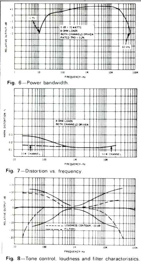
Fig. 6-Power bandwidth.
Fig. 7-Distortion vs. frequency.
Fig. 8-Tone control, loudness and filter characteristics.
Tone control, loudness and filter characteristics of the STR7065 are plotted in Fig. 8, and all conform nicely to manufacturer's claims. The use of 12 dB/octave low and high frequency filters, while requiring a few more component parts than the more commonly used 6 dB/octave types, clearly shows up advantageously when plotted against the tone control range as in Fig. 8. High degrees of attenuation at low, rumble frequencies and high "record scratch" frequencies become possible without materially affecting more important "musical" frequencies-as would be the case if tone controls or less steep cutting filters were used to correct for such problems.
Additional Measurements
Measurements not shown graphically include: capture ratio, which measured just under 1.0 dB at 1000 µV; FM alternate channel selectivity, which measured 68 dB at the same signal input level; AM suppression, which measured 58 dB; and spurious response rejection, which turned out to be higher than our 100 dB instrument capability. Hum and noise on phono (referenced to 3 mV input) read 75 dB--better than claimed by Sony, while the same parameter measured for the high level inputs was about 80 dB.
Listening Tests
The Sony STR-7065 served as our "listening set" for nearly a month (we rotate receivers and amplifiers regularly, using them for casual as well as concentrated listening for varying periods of time, depending upon backlog of sets to be tested). Largely because of its ease of handling and its excellent control features, we were unusually reluctant to displace it in favor of the next set ready to undergo our listening tests. It performed flawlessly during that long period and, a hasty check of a few FM and power measurements made before we re-packed it indicated that it was as good as the day we turned it on.
Calibration of the FM band is just about perfect, and there was no evidence of drift. AM performance was better than average for our location, and the FM band managed to pull in fifty-two useable signals, of which about 28 were stereo stations. The measured high alternate channel selectivity was obvious in our listening tests and, with our outdoor antenna properly oriented, we were able to get a few adjacent channels (only 200 kHz apart) with listenable quality.
The best thing that can be said about the amplifier section of the STR-7065 is that like all good amplifier designs, we were never conscious of its being there--it responded well at all listening levels, drove high and low efficiency speaker systems with equal ease and produced all the clean, audio power demanded by our varied listening situations. The microphone input feature will find favor with recording enthusiasts who can use it, instead of going directly into their tape recorder mic inputs. In this way, tonal deficiencies of your microphone (or even your voice) can be "sweetened up" just like the professionals do by simply connecting from the output of the "preamp out" jacks to the high level input of your recorder. This trick cannot be accomplished by feeding from the conventional "tape out" jacks--another virtue of the unique out-in arrangement provided on the Sony STR7065.
-Leonard Feldman
(Audio magazine, Nov. 1973)
Also see:
Sony Model TA-3200F Stereo Amplifier (Nov. 1970)
Sony ST-J75 FM Tuner (Equip. Profile, Apr. 1981)
Superscope R-350 AM /FM Stereo Receiver (Feb. 1974)
= = = =