Manufacturer's Specifications
Phono Section (to Tape Out) RIAA Deviation, 20 Hz to 20 kHz: ±0.2 dB.
Bandwidth: 20 Hz to 400 kHz, +0,-3 dB.
THD + Noise: Moving-magnet phono, 0.01 percent; moving-coil phono, 0.02 percent; both at 2.0 V into 600 ohms and 1000 pF from 20-Hz to 20 kHz.
S/N Ratio: Moving-magnet phono, 82 dB re: 5 mV/input; moving-coil pho no, 66 dB re: 0.5 mV input.
Phono Overload: Moving-magnet phono, 150 mV; moving-coil phono, 20 mV; both at 1 kHz.
High-Level Section (to Line Out) Bandwidth: 20 Hz to 400 kHz, +0,-3 dB.
THD + Noise: 20 Hz to 20 kHz, 0.005 percent; 20 Hz to 100 kHz, 0.01 per cent; both at 2.0 V into 600 ohms and 1000 pF.
S/N Ratio: 88 dB re: 0.5 V input, 0.5 V output.
Maximum Output: 10 V rms at Amp output; 7.5 V rms at Main output.
General Specifications
Dimensions: 14 in. (35.56 cm) W x 2.5 in. (6.35 cm) H x 9 in. (22.86 cm) D.
Weight: 5 lbs. (2.27 kg).
Price: $1,050.00.


The Bauman Pro-400 preamplifier-control unit is a straight forward looking component which, upon first encounter, evokes the question: "Why is it priced so high?" After putting it through a series of bench and listening tests, the question is partially answered. Sound quality delivered by the Pro-400 when used in conjunction with a top-quality power amp is certainly beyond reproach and there are definitely some rear-panel adjustment features which we found attractive and useful, but in our view, that doesn't fully justify the over-$1,000 price tag, even though each one is being built by hand by the President and Chief Engineer at the company's head quarters in Rosenberg, Texas.
The front panel of the Pro-400 contains six identical large black knobs, one of which is for a rotary power on-off switch. Bass and treble control knobs come next and are common to both stereo channels. Balance and volume control follow, while over at the left is a selector switch with settings for two Tape sources, Aux, Tuner and Phono. Once in the Phono position, a pushbutton switch at the lower left corner of the unit selects Phono 1 or Phono 2. Tape 1/2, tape monitor, and tape copy pushbutton switches are located between the selector and volume controls and almost a full page of the 13-page photo-offset (from a typewriter text) owner's manual explains how, by various combinations of the "TP1, TP2, TAPE MON" and "TAPE COPY" buttons, the user can do just about anything with two connected tape decks, such as dubbing from one to the other in either direction and monitoring of either one during the process, or dubbing while listening to yet another program source. Nothing truly unique here, but the unit is quite flexible. Additional push buttons near panel-center introduce subsonic filtering and defeat the tone control circuits. That's it for the front panel, whose combination of controls places the Bauman Research preamp somewhere between the "straight wire with gain" approach and the "multi-control with lots of switches and knobs" approach.
The rear panel is probably more interesting than the front. To begin, it has two pairs of phono input jacks with matching ground terminals just below. You might guess that in a preamp with double phono inputs, one of the input pairs would be set up for moving-magnet pickups while the other would be for moving-coil cartridges. Not at all! There, nestled in the same area of the back panel is another pushbutton switch which, if depressed, converts both pairs of inputs to moving-coil levels. It has been our experience that most audiophiles will have both a moving-coil and a moving-magnet phono cartridge, rather than two of each type, and this arrangement of switches just doesn't cover what we feel is the most common situation.
Near the phono inputs are two banks of small rocker switches- one bank for each channel. These select either 47 or 100 kilohm input impedances for moving-magnet phono cartridges as well as loading capacitances which can be set to between 50 and 350 pF. Actually, only three fixed capacitances per channel are built in, 50 pF, 100 pF and 200 pF, but a table in the aforementioned owner's manual shows you how, by flicking more than one of the rocker switches, you can arrive at other capacitance loading values. A small screw driver is required to activate the rocker switches- they can't be moved by human fingers which are too big.
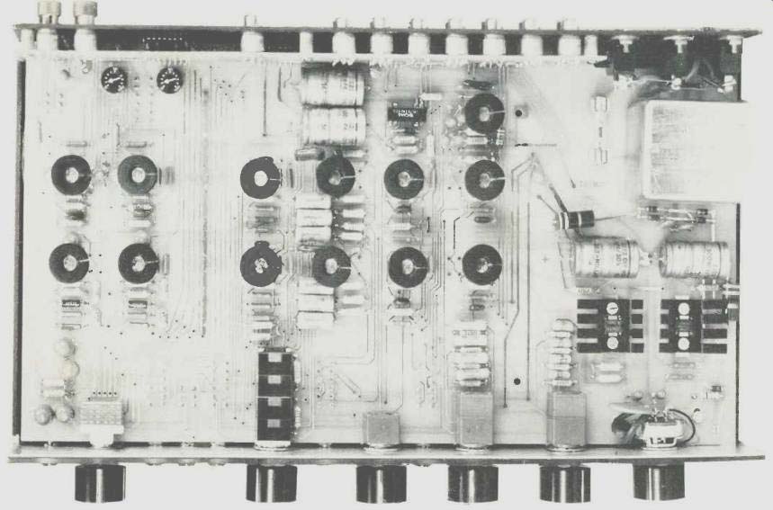
Speaking of tables, the owner's manual devotes four full pages to a listing of just about every make and model of moving-coil and moving-magnet cartridge and tells you what resistance and capacitance loading should be used with each. In case you are now wondering how moving-coil cartridges can be included in that list, what with their low out put-impedance requirements, fear not. Variable low-impedance loading for such cartridges has been included in the Bauman Research Pro-400 as well. The only hitch is that you have to remove the cover of the unit to get at them. You should follow the firm's admonitions regarding unplugging of the unit from a.c. power before poking around inside the unit, but once there you will find two small potentiometers inside, labeled Left and Right. These are calibrated in ohms, from 0 to 100, but what that really means is that additional "zeros" didn't fit on the small pots so, if you want a 500-ohm load value for your moving coil cartridge, you set each pot to 50 and mentally multiply by 10. Input jacks for the various program sources are centered on the rear panel, while out puts labeled Line Amp and Main are located next to two switched and one unswitched convenience a.c. outlets, none of which really has enough wattage capacity to work with a high-powered amplifier of the type that audiophiles using the Pro-400 are likely to want to connect. The Main output jacks will drive any impedance above 10,000 ohms, and the signal reaching them has been divided down by a full four- section master volume control for best signal to noise at all volume settings. The line-output jacks, on the other hand, will drive a 600-ohm load impedance, but to do so required bypassing the last two gangs of the volume control and routing the signal directly from the output amplifiers, thereby negating the advantage of the four-section control.
Although page one of the owner's manual says that the second half of the manual contains detailed technical descriptions, we weren't able to find anything concerning specific circuit topology, so on to the bench tests ....
Laboratory Measurements

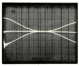
Fig. 1--Control range of the Bass and Treble tone controls.
RIAA equalization was absolutely perfect, with our VTVM needle remaining absolutely motionless as we switched frequencies from 20 Hz to 20 kHz using an inverse-RIAA input signal known to be accurate to within 0.05 dB across the audio band. THD through the phono inputs measured 0.008 percent at 1 kHz, 10 kHz, and 20 kHz, while for the moving-coil phono inputs, it measured just under the specified 0.02 percent. Moving-magnet IHF input sensitivity (for 0.5 V out put) measured 1.5 mV, while through the moving-coil phono inputs, it was 0.15 mV, indicating that the pre-preamp circuit used provides precisely 20 dB of gain. High-level input sensitivity for the same 0.5 V standardized output was 46 mV. High-level total harmonic distortion measured 0.0035 percent at 1 kHz, 0.0035 percent at 20 Hz, and 0.004 percent at 20 kHz--about as low as our test equipment can reliably measure. SMPTE IM distortion measured 0.003 percent.
Signal-to-noise ratio through the moving-magnet inputs measured a very high 85 dB (referenced to 5 mV input and 0.5 V output), while through the moving-coil inputs, it measured 69 dB (referred to 0.5 mV input and 0.5 volts output). Both S/N figures are "A" weighted in accordance with the new IHF Measurement Standards. S/N for the high-level inputs, referred to 0.5 V input and output, measured 92 dB, "A" weighted. Phono overload for the moving-magnet inputs was 200 mV at 1 kHz, while for the moving-coil inputs, it measured 30 mV before there was any evidence of clipping or overload. Frequency response for the high level inputs was flat from 3.2 Hz to 125 kHz, +0,-1 dB.
Range of bass and treble tone controls for the Bauman Research Pro-400 is shown in the spectrum analyzer sweep photo of Fig. 1, and the turnover points for both controls seem well positioned in that they do not affect midrange response materially. Maximum range of control for the bass control was ±11dB at 100 Hz, while for the treble control it was ±11 dB at 10 kHz. Maximum output before clipping was 11.0 V rms.
Use and Listening Tests
The cartridge loading system supplied in the Pro-400, despite its inconvenience for initial settings, is certainly a most useful feature of this product. We have long contended that the major differences heard between cartridges of similar price and quality was largely due to mismatching or incorrect loading, and a bit of experimenting with three moving-magnet cartridges in the $100-plus range, connected alternately to the moving-magnet inputs of the Pro-400 and adjusted properly, is indeed case. Signal-to-noise ratio was audibly improved using both these moving-magnet cartridges and a couple of moving-coil pickups currently in the laboratory. We preferred using the main-amp outputs for connection to our reference power amplifier, especially since no long cable run was involved. The four-section master volume control does keep S/N at its best even at lower listening levels.
In truth, we cannot fault the sound we heard using the Pro-400 in any way. The subsonic filter (with its 3-dB cut-off at 13 Hz) introduces no audible bass roll-off whatever from any program material we were able to audition. Overall sonic balance was excellent, with highs particularly clean and de void of any hardness often attributed to some solid-state preamp designs. Despite the question of the unit's price being only partially resolved, we are certainly willing to grant all sorts of accolades to Bauman Research for the basic bench performance provided by their Pro-400 unit, and cannot fault it sonically.
-Leonard Feldman
(Audio magazine, Nov. 1979)
Also see:
BGW Systems Model 203 Stereo Preamplifier-Control Center (Equip. Profile, Nov. 1977)
= = = =