Manufacturer's Specifications:
Frequency Range: 16 Hz to 20 kHz.
Bandpass Filters: 32 single-pole-pair 1/3-octave BW at 1/3-octave intervals.
Display Modes: 1/3 or 1 octave, switch selected.
Sensitivity: 15.2 mV unbalanced, 0.76 mV balanced for full-scale indication.
Display Accuracy: ±1.0 dB, full scale to -40 dB; ±1.5 dB to-50 dB; ±3.0 dB to -60 dB.
Detector Filtering: Dual section.
Time Constants: Fast, 15 mS and 47mS; slow, 15 mS and 375 mS.
Noise Generator: Pseudo-random type.
Repetition Rate: 2.1 seconds.
Pink Filter Accuracy: ±0.5 dB from 16 Hz to 20 kHz, bandpass limited at 10 Hz and 40 kHz.
Output Level: Variable, 1.1 V rms maximum.
Dimensions: 19 in. (483 mm) W x 7 in. (178 mm) H x 16 in. (419 mm) D.
Weight: 22 lbs. (10 kg).
Price: $2,195.00.
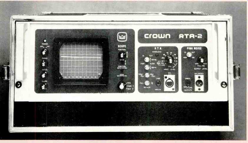
The Crown RTA-2 is an excellent configuration of a third-octave real-time analyzer and offers superior performance for a very reasonable price. The front panel is divided into three groups. The scope section uses a 5-in. CRT with an overlaid graticle. There are six vertical divisions, and scaling can be set for 5 or 10 dB/division. There are 11 divisions along the horizontal with octave-spaced center frequencies printed on the bottom, from 16 Hz to 20 kHz. The graticle, which adds blue filtering to the display, also has reference marks every one-fifth of a vertical division and every one-third division horizontally. The graticle itself has controllable illumination, a useful feature, particularly for photography or low-light-level situations.
There are also pots for controlling focus, trace intensity and vertical position, and three screwdriver-adjust pots for vertical gain, horizontal position, and gain. A rotary function switch selects RTA, AUX 1 or AUX 2. RTA, of course, is the normal real-time analyzer mode. AUX 1 or AUX 2 selects inputs from corresponding jacks on the rear panel for displaying external signals on the scope. This is a nice feature and it could be extremely useful to some, while the manufacturer can include it at relatively small cost. AUX 1, for example, could be used to display an X-Y phase comparison, and AUX 2 could be used to show a swept frequency response.
Low-signal-level detectors help prevent CRT burns by gating off the beam if there are no deflection signals, another example of careful design.
The RTA section has inputs for both line (phone) and balanced mike (XLR). The input level can be attenuated up to 70 dB in 10-dB steps, plus the 40 dB available with a continuous vernier. The switch also has HI and LOW calibration positions which feed pink-noise levels 20 dB apart internally to the scope for system calibration, a feature overlooked by some manufacturers. There are four push-button switches which select fast or slow detector responses for filters from 16 Hz to 630 Hz and from 800 Hz to 16 kHz, vertical scaling of 5 or 10 dB/division and /3 or full octave display. Any overload is indicated by a red LED.
The pink-noise section has both balanced (XLR) and un balanced (phone) output jacks. A button switch can be used to introduce 40-dB attenuation, which is necessary for micro phone level outputs. The output-level pot is pulled out to switch on the noise generator. On the rear panel, there are pin jacks for noise out, vertical and horizontal (sweep) out for external display, and vertical and horizontal in for both AUX 1 and 2. There are also screwdriver-adjust pots for set ting both sensitivities for the two inputs. There is a line input phone jack, which is overridden by use of a front-panel input jack. The astigmatism control for the scope is on the cover over the CRT base.
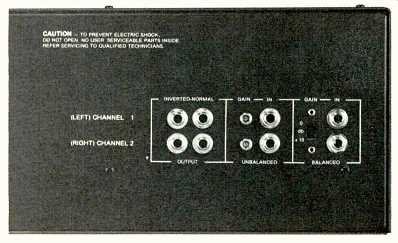
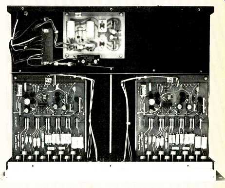
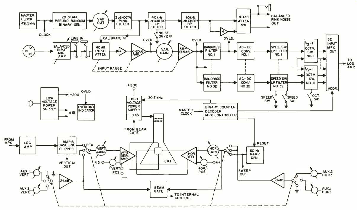
Fig. 1--Block diagram.
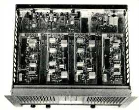
Both top and bottom covers were removed to get a really good look at the internal construction and design. There were two large PCBs for the 32 filters, one above the other.
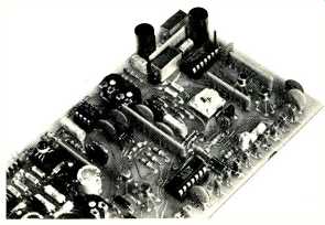
The removal of five hold-down screws allowed the upper board to swing up on three post hinges, but it was still connected electrically with a multi-pin cable. This scheme is one of the best I've seen for solid support of a PCB while providing ready access for adjustments and troubleshooting. The deflection PCB is mounted between the filter cards and the CRT. The input PCB, which includes the pink-noise genera tor, is mounted near the bottom of the unit. All of the soldering was excellent with very little flux residue. Components were of high quality, with precision polystyrene and polycarbonate capacitors and sockets for all ICs among the many examples. The line fuse was mounted internally in clips; my preference would be for an external holder. This is a very minor deviation, however, for this professional unit which is both rugged and refined.
Circuit Description
Figure 1 is the block diagram of the RTA-2, and I expect that most readers will be able to follow the various signal and control paths. Do note that the 491.5-kHz master clock drives the pseudo-random noise generator as well as the filter multiplex controller. One of the refinements of the unit's design is that there are FET speed, or smoothing, switches in each filter channel. The a.c.-d.c. converter, which is a precision rectifier, is followed by an op-amp with a 15 mS time constant, and it drives an RC network with a time constant of 47. mS. This configuration is used in all of the filter channels when they are set for Fast. When the speed switches are put in Slow, the FET switches add 33 uF to each RC net, increasing the time constant to 375 mS and smoothing the outputs greatly. CMOS switches are used to combine the outputs of sets of three filters to generate the octave-band display when this option is selected at the front panel. The filter multiplexer output feeds the log amp which drives the vertical channel of the scope. The horizontal 60-Hz ramp generator is reset with a countdown from the master clock.
Performance
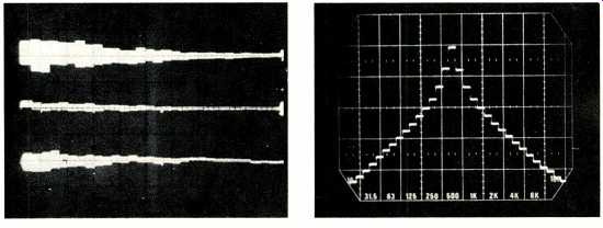
Fig. 2--Pink-noise responses.
Top: RTA-2 source with filters on Fast.
Middle: RTA-2 source with filters on Slow.
Bottom: Gen Rad 1382 source with filters on Slow.
(Vertical scale: 5 dB/div.)
Fig. 3--Display of sound-system response. (Vertical scale: 10 dB/div.)
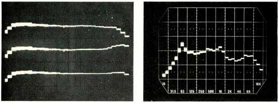
Fig. 4--Response to a 500-Hz tone. (Vertical scale: 10 dB/div.)
Fig. 5--Tape recorder setup. Top: Response before head alignment. Middle: After alignment, but before bias and EQ adjustment. Bottom: After adjusting bias and EQ. (Vertical scale: 5 dB/div.)
==================
A Brief Look at Analyzers
Whether we talk about music, noise or test signals, we can use either time or frequency domains. When such signals are displayed on a scope, we are observing the characteristics in the time domain. For steady test tones, such as sine or square waves, the display is steady and can be examined at leisure.
We may know that the square wave includes odd harmonics of the fundamental, but they are not laid out for us to see what all the components are. Without considerable experience, the examination of noise (or music) with a scope is an exercise in futility.
We can, however, use some form of Fourier analysis equipment and examine the signals in the frequency domain. This process is spectrum analysis, although the term "spectrum analyzer" usually refers to an instrument which is swept-tuned, with a fixed i.f. and filter, detector and "video" filtering, or smoothing. The output is displayed on a CRT, perhaps a storage type for use in slow sweeps. A wave analyzer per haps processes the signal the same way, but it may well be hand tuned, with a meter instead of a CRT. It is possible, of course, for analysis to be made with a set of full- or 1/3-octave filters, switching to each in turn for indication on a meter.
A great deal of attention in recent years has been given by both manufacturers and users to real-time analyzers. It may strike the observer of this scene that all equipments are not equal, or can't be, with prices ranging from $200 to over $20,000. In a great simplification, we can say that one man's "real time" is not another man's "real time." In one case, the criterion is that all incoming data are processed and displayed with essentially no delay. The criterion for the RTA types popular for equalization, however, is that the display show the entire spectrum continuously, showing changes only at a rate needed for the task. The time required to charge all of the filter, is accepted, as it is a small part of the time required for the task. This RTA design consists of a number of contiguous filters which are continually fed by the incoming signal. Most such units will not display the spectrum of a pulse, for the filter detectors are averaging type, rather than peak responding. The fast RTAs, however, using time compression or FFT techniques will even capture transients and display their spectra.
Turning our attention again to the spectrum analyzer (swept-tuned), we can see that it offers a major advantage over the lower-priced RTA ($4,000 or less), and suffers a major disadvantage for some purposes. The major advantage is that the i.f. filter has very steep slopes and the bandwidth can be set very narrow. This is just what is needed for the examination of the harmonic structure of a signal. Noise contributions are also reduced, and discrete components more than 70 dB below the fundamental are easily examined. The major disadvantage is that because it is swept-tuned and displayed, portions of the spectrum are shown in turn over a period of time, rather than simultaneously. The narrower the filter bandwidth, the slower the sweep must be, adding delay between the first part of the spectrum and the last.
The spectrum analyzer is the required instrument for the analysis of the distortion products, swept response of filters, TDS (time-delay spectrometry), and other such tasks. (The high-priced RTAs may have such capabilities, although some are limited in dynamic range, in comparison.) In general, spectrum analyzers do not analyze or display noise well with log sweep, which is preferred for checking the frequency response of an audio system. When we want to look at noise levels on an octave or 1/3-octave basis, the contiguous-filter RTA gives us the display we want, with the total spectrum divided neatly into a number of bands. The constant-percentage bandwidth of the filters combines with a pink-noise input for a flat display when the response is flat. Unless its filter skirts are steeper than most, this type of RTA will not display low-level distortion products. For equalization, recorder alignment, and even program monitoring with fast time constants, however, these RTAs are the best choice.
-H.A.R.
==================
The first check made of the Crown unit was of frequency response with a CW input signal. The peaks of all of the filter responses were within 0.2 dB from 16 Hz to 20 kHz over a wide range of input levels and attenuator settings. The center frequencies were accurate with no exceptions, usually within 1 percent. The RTA-2 response to pink noise was checked using both the internal generator and a separate Gen Rad unit. Figure 2 shows the results on a separate storage scope.
With the RTA-2's generator and fast filter responses, there is a noticeable spread at the lowest frequencies (5 dB/vertical division). With slow filter responses, the spread is greatly reduced. Note that with the Gen Rad source and slow responses, however, there is a greater spread. The reason is this: The Gen Rad output is truly random, and it includes some output levels that occur infrequently. The pseudo-random noise of the RTA-2 does not include some levels of lower statistical importance, so there is less spread in the display for the same smoothing.
Figure 3 shows a typical filter response to a single tone, 500 Hz in this case. The Q is fairly high for the single-pole-pair design, and the final 6 dB/octave slopes are reached at about ± 2 octaves. Filter sections crossed over accurately in frequency at the desired 3 dB down. Levels could be set and read accurately, whether set to 5 or 10 dB/div. As received, the measured scaling was 4.9 dB/div for one setting, and 9.7 dB for the other. These are excellent results, and a little touch-up of vertical gain resulted in a figure of 9.9 dB/div over the entire 60-dB range--superb. The input attenuator steps were exactly 10 dB, and the vernier had a 74-dB range.
The internally fed noise calibration levels were exactly 20 dB apart. Because the graticle is overlaid on the CRT, there is some parallax, which should be considered for high-accuracy work or making scope pictures. The range of the vertical position control was about three times the screen height.
The balanced-microphone input sensitivity was 0.71 mV, and that for the unbalanced line was 14.8 mV. The mike preamp gain can be adjusted internally from +10 to +26 dB; the RTA-2 is supplied with it set at +20 dB. The noise genera tor output was a maximum of 1.1 V, which the output pot reduced to 7 mV. With the 40 dB attenuation, the range was 11 mV maximum, down to 0.07 mV. All impedances were as specified. Checking the back panel jacks showed that the Sweep Out was from 0.0 to +10.8 V every 16.6 mS. Vert Out was an accurate 1V/10dB, with a range of 2 to 8 V, nominal.
This output is not affected by the scope position setting. The AUX input sensitivities were 65 mV/div vertical and 50 mV/ div horizontal. The input level pots allow reducing sensitivity to match high-level drive signals. With the removal of inputs, the low-signal-level detector gated off the CRT beam in 3 seconds.
In-Use Test
The first step was to listen to the noise output from the Crown unit. There was a bump-like sound that occurred every 2 seconds, but it was a small part of the total output, a minor distraction at most. The knobs on the unit are of good quality, but I would prefer a bar-type on the attenuator for greater ease in turning. Figure 4 shows the use of the RTA-2 in doing recorder alignment. This is one of my favorite uses for a third-octave RTA, and the response to 20 kHz helped to do a good job quickly. Figure 5 shows the display of a sound-system response with an E-V RE-55 mike used for the pickup.
is obvious immediately that the tweeter output is on the low side. A change in the level setting appears to be the best first step. The Slow response for the filters was used for these and other equalization-type tasks. The Fast mode was best for use as a music monitor, and it was very interesting to see the change in the display spectrum when changing types of music or to another FM station. Sharper filter skirts would have aided seeing the harmonic structure, particularly at the frequency extremes. A group of teenagers thought it was a marvelous addition to their disco lighting, and it certainly showed up well in the darkened room. Screen intensity could be set very high without significant trace widening, with the trace easily observable at a light level of over 3000 footcandles. That's outside, although not in direct sunlight which would probably need a shade.
There were a few times that I wished the RTA-2 included some form of memory, but including a storage-type CRT and its circuitry would have increased the cost significantly, to say nothing about the weight increase. Actually the purpose of the storage shown in Figs. 2 and 4 was to generate better illustrations for the article. The storage was not needed to do the tasks depicted; in fact, it delayed the recorder alignment.
An LED type of display might have saved some space, but a good part of the total volume of the Crown unit goes with the excellent accessibility for adjustment and maintenance.
An advantage of the analog display of the CRT is its higher resolution.
The instruction book consists of a three-ring notebook with a total of over 60 pages of material. There are several pages of general information and specifications, including response plots. It is true, as the manual states, that there are a good many possible uses, and some of them should have been more fully described to aid the user in the initial learning phase. There is an excellent block diagram, and some discussion of circuit theory, which would benefit from some expansion. There are excellent quality schematics and layouts of each of the PCBs. An interconnection diagram would be a desirable addition to facilitate following signal and power paths among the cards. There is a very detailed parts list, covering some 30 pages with each of the filter channels listed separately. Filter center frequencies should have been shown here, but were not. In toto, the information presented is quite broad, and there is great depth in important areas. The three-ring binder format should facilitate keeping the manual up-to-date, and adding application notes, troubleshooting guidelines, etc.
The Crown RTA-2 may now be purchased directly from Crown ($2,195.00), and they are making an AKG C451E system available for just $100.00! A portable field case is $100.00; a shipping case is $120.00. The RTA-2 offers outstanding performance for measuring system responses, equalization, recorder alignment, etc., for use in the laboratory, at the site, in the studio or on the road.
-Howard A. Roberson
=============
Crown AD:
THE RATIONAL AMPLIFIER, FROM CROWN.
Sound reproduction systems of the 1980's will include "smart" components--components that react to their environment, that know how to protect themselves, and know how to keep functioning in that environment.
They belong in your future.
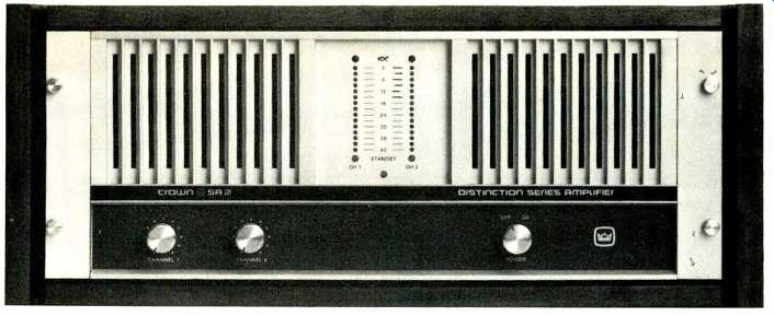
The Crown Distinction SA2 stereo power amplifier is a rational amplifier. It analyzes its own behavior in terms of its immediate environment.
It protects itself. It keeps on driving your speakers with power reserves that may amaze you. It's available now.
The SA2 has four on-board computers that constantly monitor and control the performance of the amp.
The SA2 knows when it can use its full power capabilities, and when it has to cut back in order to prevent damage to itself.
The SA2 is sonically so accurate that its distortion and response levels require highly sophisticated test instruments to measure. However you measure them, the SA2 translates into beautiful music.
The SA2 incorporates new system engineering concepts that won't easily be duplicated. It is unique.
SOA-it's important! The safe operating area (SOA) of a power transistor is defined by the internal temperature of the transistor.
That temperature must be kept below a critical level or the transistor will be damaged, an expensive and bothersome event.
Audio circuit designers have always known that SOA is difficult to measure, since it varies widely de pending on what the transistor is being asked to do. Designers have had to estimate arbitrary limits for output voltage or current in order to protect output transistors, leaving much of the capability of the power transistor unused. Such designs are not as efficient as the SA2 has proven to be.
SOA measured by Crown.
Crown's engineers several years ago developed a special test instrument to accurately measure the changing SOA of power transistors under varying loads. To the best of our knowledge, it's still the only such test equipment in the audio industry. From the work done on this instrument, Crown developed the mathematics of output device behavior needed to design the computer-con trolled protection system of the SA2 amplifier. That system makes it possible, for the first time, to utilize fully the capabilities of power transistors in an audio amplifier.
On-board computing.
The SA2 protected-power system starts with the output transistor data developed by Crown, which is now in computer memory at Crown. Analog computer circuits built into the SA2 are programmed from data about the SOA of the output devices. The on board computers obtain real-time input from sensing devices which re port current, voltage and thermal behavior of the output transistors.
The computers then describe, in real time, what the transistors have been doing, what they are being asked to do, and compute whether the result of all that could drive them outside their SOA.
If the on-board computers predict operation outside the SOA, the output is limited automatically and immediately. The computers also limit output only to the degree necessary, so that output power is always at the maximum safe level for the existing environment. The limiting is self correcting, and full output power is automatically restored as soon as the demands on the output devices no longer threaten their SOA limits.
All this happens in micro-second time, with the output devices being constantly checked.

=======
SPECIFICATIONS
Stereo Output Power:
220 WATTS PER CHANNEL MINIMUM RMS (BOTH CHANNELS OPERATING) INTO AN 8 OHM LOAD, 20Hz-20KHz AT A RATED RMS SUM TOTAL HARMONIC DISTORTION OF 0.05% OF THE FUNDAMENTAL OUTPUT VOLTAGE.
350 WATTS PER CHANNEL MINIMUM RMS (BOTH CHANNELS OPERATING) INTO A 4-OHM LOAD, 20Hz-20KHz AT A RATED RMS SUM TOTAL HARMONIC DISTORTION OF 0.08% OF THE FUNDAMENTAL OUTPUT VOLTAGE.
600 watts per channel minimum RMS (both channels operating) into a 2 ohm load, at 1KHz; rated RMS sum total harmonic distortion of 1.0% of the fundamental output voltage.
Monaural Output Power:
700 WATTS MINIMUM RMS INTO AN 8 OHM LOAD, 20Hz-20KHz AT A RATED RMS SUM TOTAL HARMONIC DIS TORTION OF 0.12% OF THE FUNDAMENTAL OUTPUT VOLTAGE.
440 watts minimum RMS into a 16 ohm load, 20Hz-20KHz, at a rated RMS sum total harmonic distortion of 0.08% of the fundamental output voltage.
1200 watts at 1KHz into a 4 ohm load, at a rated sum total harmonic distortion of 1.0°%o of the fundamental output voltage.
Stereo Hum and Noise:
115dB below rated output, "A" weighted.
Stereo IM Distortion:
Less than 0.01% from 0.25 watts to 220 watts into 8 ohms per channel.
Stereo Stewing Rate:
Greater than 30 volts per microsecond.
Stereo Frequency Response: +0,-1.5dB, DC-80KHz.
=======
Continuing safe output.
Output power is never, in the Crown SA2 system, limited arbitrarily. Your SA2 continues at full power as long as output transistor safe operating area is not violated. Where other amps would simply thermal out and shut down, the sensing and protection concepts employed in the SA2 keep the maximum safe power flowing to your speakers under any and all conditions.
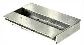
Unique heat sink design.
The Crown SA2 heat sinks may be new to most home audio system owners. The finned aluminum channels in these Crown-made heat sinks are much more efficient than castings because they rapidly dissipate large amounts of heat to keep the SA2 at its most efficient thermal level. In addition, a rear-mounted fan keeps a gentle flow of air moving through the amp. If the chassis should heat up, the fan automatically shifts to a higher speed until the amp returns to a cooler operating level.
And much more.
When we designed our rational amplifier, we didn't stop with the innovative protection system. The SA2 is built around a carefully thought out circuit design that contributes to immeasurably low distortion. For instance, a junction field-effect transistor (J-FET) input is incorporated into a multiple feed-back design to reduce noise and distortion while offering perfectly controlled transient response.
The main power supplies and transformers for each channel are separate. The SA2 mechanical design emphasizes sensible weight distribution and easy handling. The Crown IOC distortion indicating system notifies you about deviations in output waveform before any kind of distortion becomes audible. Sub-audio speaker protection is provided by monitoring the output and turning off the affected channel if necessary.
Indicating dynamic range.
You will be pleased at the elegant concept of reporting music peaks in the Crown SA2. The vertical LED meters on the front panel actually display two values for each channel.
The top light will always be a peak-hold display with a four second delay.
The other light, which may be coincident with the peak-hold indication, but is usually below it, is a running peak indication. The differences between those two will enable you to evaluate the dynamic range available in the music source.
Built by Crown.
The SA2 is a Crown product. If you're new to high-quality that may not mean much, so we suggest you ask an experienced friend about us. He will tell you about the Crown reputation for reliability, for sonic excellence, for service. We're proud of that reputation, so we work very hard to uphold it.
Crown Care.
Every SA2 is thoroughly tested at the factory, and a certified proof-of-performance report is attached, detailing the measured specifications for your SA2, which are often better than the published specifications.
Every SA2 is also covered by the full Crown warranty, by which Crown guarantees, at no cost to the current owner, repair or replacement of any SA2 which does not perform to original, published specifications for a period of up to three years from date of original purchase. This warranty also covers round-trip shipping for the unit. We believe that this protection for your investment is the finest available anywhere.
We think the SA2 is quite simply the finest audio power amplifier you can buy, one which will expand your musical horizons. But before you make up your mind, you may want more information. You can examine the SA2, and the product manual, at your nearest Crown Distinction dealer, or you can send us five dollars with the coupon and we'll send you an SA2 manual. If you return the manual, we'll return the five dollars.
Listen to the Crown SA2. It's a rational decision.
crown 1718 W. Mishawaka Road, Elkhart, Indiana 46514
Innovation. High technology. American. That's Crown.
(Audio magazine, Nov. 1979)
Also see:
Crown PZM-180 Pressure Zone Microphone (Equip.Profile, Mar. 1985)