Manufacturer's Specifications:
Type: Moving coil with van den Hul stylus.
Output Voltage: 0.25 mV rms at 5 cm per second.
Frequency Response: 20 Hz to 10 kHz ±1 dB, +3 dB at 20 kHz.
Channel Separation: 25 dB at 1 kHz.
Dynamic Compliance: 16 x 10^-6 cm per dyne, 100 Hz.
Channel Balance: Within ±1 dB at 1 kHz.
Recommended Tracking Force: 2.00 to 2.50 grams.
Vertical Tracking Angle: 18 degrees.
Input impedance: 3 to 5 ohms.
Weight: 5.5 grams.
Recommended Tonearm Type: Light to medium mass.
Price: $550.00.
Contrary to widespread belief, the moving-coil phono cartridge is not a recent invention, only its use has become popular within the past decade. Actually, the moving-coil cartridge was invented by Arthur C. Keller of Bell Laboratories in 1929, utilizing either a diamond or sapphire stylus. The invention was announced substantially later at the 67th Audio Engineering Society Convention in New York on October 21, 1980, where Keller presented his paper, "Early Hi-Fi and Stereo Recording at Bell Laboratories (1931-1932)." The first commercial version of Bell's moving-coil cartridge was called the 7A Reproducer, and it was followed shortly thereafter by an improved version, the 9A Reproducer. An interesting related fact is that Keller and his associate Ira Rafuse had already completed their work on the single-groove 45/45 stereo system in 1932, one year before Alan Blumlein of England. Why Bell Laboratories did not choose to announce these inventions in 1932, but waited until 1980, may never be known.
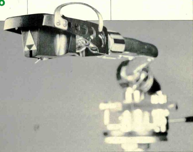
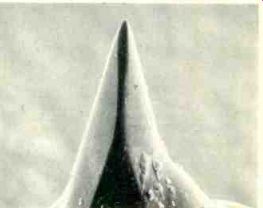
In the interim, the moving-coil phono cartridge has undergone many refinements, and one of the latest is embodied in the Mirror Image Transducer (MIT-1) distributed by John Marovskis Audio Systems, Inc. Perhaps the most interesting feature of this cartridge is its use of the van den Hul stylus, named after its inventor, A.J. van den Hul, of Delft, The Netherlands. This stylus has a profile as close as possible to that of a cutting stylus so as not to degrade records in playback. The area of groove contact with this stylus is a thin line, the same as with a cutter stylus. The fit to the groove is, then, quite exact even though the area of the footprint of the van den Hul stylus is actually about the same as that of an elliptical stylus, though of course very different in shape. The van den Hul contact area, as measured using a Scanning Electron Microscope (SEM) picture (see Fig. 1), is 143 µ long with a constant contact diameter of 10 µ over its entire length.
By contrast, the contact area of other styli more often resemble broad ellipses.
This occurs because a normal elliptical stylus has a quite narrow frontal angle which results in a small area of contact with the groove walls near the bottom of the groove. Vertical tracking force (VTF) then deforms this area of contact in the groove to a degree sufficient to generate a force required to counteract the VTF needed to track the modulations. This groove deformation, with conventional styli, is quite extensive and is close to the elastic limits of the vinyl at the maximum VTFs commonly specified.
The van den Hul stylus has a frontal angle of about 88 degrees with nearly straight groove-contact lines. These contact lines, in fact, extend well above the groove walls even for the most highly modulated grooves. The fit to the groove is thus very precise, about 80 percent.
More significantly, this fit is maintained with the MIT-1 cartridge even at high modulation levels. Since the contact radius on the van den Hul stylus does not vary along the length of this line contact, unlike other line contact profiles, extraordinary resolution of complex information is possible, even at high modulation levels. The deformation of the groove by the VTF is much less extensive with the van den Hul stylus because of the good fit to the groove allowed by the stylus geometry. Thus, much greater safe-tracking forces are possible than with standard stylus profiles. The MIT-1 requires a minimum vertical tracking force of 2 grams and a maximum of 2.5 grams--a range providing optimum tracking of high-velocity modulations.
SEM studies have shown that increasing the VTF by 1 gram above the maximum recommended when using certain standard stylus profiles can result in permanent groove deformation after only a single play. On the other hand, the MIT-1 cartridge can be used with tracking forces sufficient to nearly collapse the suspension without introducing visible permanent deformation of the groove.
The van den Hul stylus then appears to be more gentle on the groove than other stylus profiles, provided the stylus is positioned precisely in the groove. This paradox is very welcome in view of the very narrow contact line of this profile (10 µ). However, this paradox is true provided the azimuth angle is adjusted so that the stylus is placed in the groove in the same orientation as the cutter stylus cut the groove. With the van den Hul stylus there is less than 1.5-degree allowance, while for other styli this adjustment is relatively non-critical and only introduces a degradation in crosstalk.
Unless this azimuth adjustment is correct, it is possible for the van den Hul stylus to deform the misaligned groove beyond the elastic limits and thus introduce record damage which, in extreme cases, actually takes the form of shaving material off the groove walls. To use the van den Hul stylus properly, the user must be assured that the stylus is in correct alignment with some visible reference mark that can be used to place the stylus in proper orientation to the groove.
In assembly of the MIT-1, the logo on the front of the cartridge is carefully aligned by optical means with the front axis of symmetry of the stylus. When installing the cartridge, the user must carefully align the logo with respect to the record surface. A simple reflection of the bottom of this logo in the record or in a mirror must tie visible as parallel with itself.
When this is achieved, the stylus is properly aligned in the groove.
The choice of materials in the moving mechanism have been made to take advantage of some unusual benefits and possibilities that the van den Hul stylus allows in record playback, as well as to satisfy certain requirements for its use. In general, the suspension and cantilever must be more robust and have a high degree of stiffness. Torsional effects under dynamic conditions must be held to a minimum. Because of the good fit to the groove, there is a much more tight ri 11-3% groove coupling with the van den Hul stylus than with conventional profiles, and this, in turn, results in differences in the forces that the groove modulations can exert on the moving mechanism.
Particularly interesting is the need for more moving mass with the van den Hul than for conventional styli. Reasons for this arise from the nature of the groove geometry as a function of modulation levels. In the MIT-1 the ultra-low mass or minimum mass allowed by existing materials is replaced by the concept of optimum mass.

Fig. 1--Lateral SEM view of the van den Hul stylus in the MIT-1. The dark
area In the center of the stylus, from the tip to where it begins to widen,
is the actual groove contact area, which is 143 p. long by 10 p. wide. (x300
magnification.)

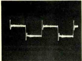
Fig. 2--Response to 1-kHz square wave.

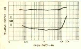
Fig. 3--Response of left channel and separation.
A reason for this difference in design approach is because it is desirable to minimize all deformation of the vinyl groove in playback with conventional styli, but not with the van den Hul stylus.
Conventional styli do not look like the record cutter styli, and consequently a groove deformation in playback results in an additional source of distortion.
Moreover, SEM studies also show that the record groove geometry can differ greatly from the record cutter geometry when the modulation is large. One important effect is due to the deformation of ;he groove by the spring-back of the lacquer master into which the modulations are cut. Measurement of groove cross sections revealed that grooves with small modulations have walls that are close to the 90-degree angle of the cutting stylus. But, for large modulations the groove walls can make an angle of less than 80 degrees. This is a very large deformation and gives rise to a dynamic modulation of the crosstalk in playback because the entire playback system expects an orthogonal relationship for the groove walls. It should be noted that a conventional stylus, which fits near the bottom of the groove, increases this type of distortion in playback unless the dynamic deformation of the vinyl in playback can be minimized. The minimum-moving-mass concept can help to bring this about.
A different circumstance is found when a van den Hul stylus is used. The 88-degree angle required for good groove contact at small modulation levels can result in a spurious vertical modulation that is related to the program dynamics. The van den Hul stylus can be literally pinched out of the groove in those instances where the groove angle becomes less than the 88-degree angle of the van den Hul stylus. The very nature of the van den Hul profile requires that lacquer spring-back and vinyl deformation be taken into consideration. This can be achieved by introducing the notion of an optimum mass for which one obtains, under dynamic conditions, a degree of deformation in vinyl that complements the spring-back deformation introduced in the cutting process and transferred to the record by duplication. Because the amount of spring-back is substantial, a significant improvement in sonic performance can be realized. It should be noted that this correction is only possible because the spring-back deformation and dynamic deformation under playback are both related to the geometry of the cutting and playback styli. When these are similar in appearance, the two can be made to at least partially cancel one another. The van den Hul stylus of the MIT-1 phono cartridge represents an attempt to correct for effects derived from the elasticity of the two media, i.e., the spring-back distortion depends on the material composition of the lacquer master and upon the cutting temperature, just as the degree of dynamic deformation upon playback also depends upon the vinyl composition and temperature.
The JMAS MIT-1 phono cartridge comes mounted on a metal plate which is encased in a black velvet box. The cartridge is supplied with a small screwdriver, mounting screws and nuts, a stylus brush, and four color-coded wires with gold-plated contacts for connecting the cartridge to the shell. The cartridge has a removable stylus guard rather than the hinged guard usually supplied nowadays. The stylus assembly is not user replaceable. Except for the van den Hul stylus, the cartridge is manufactured by the Coral Audio Corp. of Japan to JMAS specifications. The cantilever is made of a beryllium alloy and the van den Hul stylus is obtained from Fritz Gyger Co., Switzerland. All optical alignments and final adjustments of the mechanism are performed by JMAS. Because of the minute size of the moving coils, the signal output is very low and a step-up device is needed to raise the output voltage to a level that can be used with the usual preamplifier phono input stages. I tested the MIT-1 cartridge with the a.c.-line powered Audio Standards MX-10A pre-preamplifier, which proved to be excellent, and the battery-powered Marcof PPA-2 pre-preamplifier, which was also very good.
However, all the reported measurements and listening tests were made with an Audio-Technica AT-650 Moving-Coil Matching Transformer set for an input impedance of 3 ohms. The AT-650 proved to be an excellent passive matching device for the MIT-1.
Measurements
The MIT-1 phono cartridge was mounted in an Audio-Technica head-shell and used with the Audio-Technica Model AT-1010 tonearm mounted on a Luxman PD-555 vacuum turntable. The cartridge was oriented in the headshell and tonearm with the Dennesen Geometric Soundtracktor. Laboratory tests were conducted at an ambient temperature of 74° F ± 1° (23.33° C) and a relative humidity of 68 percent ±3 percent.
The tracking force for all reported tests was at 2.4 grams, with an anti-skating force of 2.5 grams. The cartridge, when lightly tapped, was found to be slightly microphonic. As is my practice, measurements were made on both channels, but only the left channel is reported unless there is a significant difference between the two channels, in which case both channels are reported for a given measurement.
Frequency response, using the Columbia STR-1 70 test record, was +0.5 dB from 40 Hz to 6 kHz, +1 dB at 8 kHz, +1.9 dB at 10 kHz, and +3.7 dB from 15 to 20 kHz. Separation was 23 dB at 1 kHz, 23.5 dB at 7 kHz, 23 dB at 10 kHz, 19 dB at 15 kHz, and 12 dB at 20 kHz. From these data, it is evident that the MIT-1 has an excellent frequency response and a most satisfactory high-frequency separation.
The 1-kHz square-wave response shows a large overshoot followed by ringing which decayed rapidly. The overshoot is probably due to the under-damped high-frequency resonance of the cartridge, which is in the ultrasonic range. The cartridge-arm low-frequency lateral resonance is at 8 Hz at +6.5 dB amplitude. The vertical resonance is about 8 Hz.
The following test records were used in making the reported measurements: Columbia STR-170, STR-100, STR112; Shure TTR-103, TTR-109, TTR110, TTR-115; Deutsches Hi-Fi No. 2; Nippon Columbia Audio Technical Record (PCM) XL-7004, and the Ortofon Direct-Cut Pickup Test Record 0001.
Wt., 4.8 g; d.c. res., 6.8 ohms; opt. tracking force, 2.4 g; opt. anti-skating force, 2.5 g; output (using AT-650 transformer), 2.77 mV/cm/S; IM distortion: (4:1) +9 dB lateral, 200/4000 Hz, 3.2 percent; +6 dB vertical, 200/4000 Hz, 4.6 percent; crosstalk (using Shure TTR-109), 23 dB; channel balance, within 0.5 dB; trackability: high freq. (10.8-kHz pulsed), 30 cm/S; mid-freq. (1000 and 1500 Hz, lat. cut), 31.5 cm/ S, low freq. (400 and 4000 Hz, lat. cut), 24 cm/S; Deutsches Hi-Fi No.2 300-Hz test band was tracked cleanly to 86 microns (0.0086 cm), lateral at 16.20 cm/ S at +9.66 dB and 55.4 microns (0.00554 cm), vertical at 10.32 cm/S at +5.86 dB. The latter measurements are excellent, especially the vertical measurement, because not many cartridges can track the higher level 300-Hz bands on this test record.
The JMAS MIT-1 phono cartridge played all the test bands except for level 5 of the violin, where there was a hint of stridency, on the Shure Obstacle Course Era III. On the Shure Obstacle Course Era IV, the cartridge had difficulty with the harp and flute test band, level 4, where the flute started to break up, and the flute and bells test band, level 5, where stridency was heard. Overall, the MIT-1 performed superbly inasmuch as it's a very rare commercially available phonograph record that has recorded musical signals with a velocity greater than 20 cm/S, the average being around 15 cm/S. Level 4 of the harp and flute and level 5 of the flute and bells are recorded at velocities over 45 cm/S and over 50 cm/S, respectively.
Use and Listening Tests
As usual, I performed many hours of listening tests both before and after measurement. While listening to a wide variety of records, I especially noted the excellent sonic clarity, transient response, and transparency of sound, as well as the lack of detectable coloration, particularly when reproducing the high recorded levels present on most direct-to-disc recordings. I did not find the MIT-1 to be bright despite the 1-dB rise at 8 kHz, and the bass was sonically well defined and tight. Voice was reproduced rather well, and applause definition was excellent. After listening to the MIT-1 phono cartridge over an extended period of time, I am of the opinion that it is one of the finest phono cartridges I have ever listened to in many years of testing cartridges.
-B. V. Pisha
--------------
(Source: Audio magazine; Nov. 1981)
Also see:
Link | --Micro Acoustics 630 Phono Cartridge (Mar. 1984)
= = = =