
By Richard Kaufman
Multiple-feedback filters offer several advantages over other active types, and their tedious design can be rapidly solved with this computer program.
The multiple-feedback filter is a useful design, offering a number of advantages over other types of active filters. But the design is neither simple nor straightforward, and requires tedious calculation. This computer program eliminates the chore of computation, allowing the designer to quickly evaluate many design alternatives and choose those best suited to his application. This program was written for the Apple II+, but with a minimum amount of translation will run on any machine equipped with BASIC. A major advantage of the multiple feedback filter is that it runs in the inverting mode. This reduces common-mode errors, resulting in less noise. Smaller capacitors than in other designs can often be used; such caps are more readily available and cost less. The gain of this filter can be set independently of other parameters, and so gain need not be set elsewhere in the system.
The Filter Circuit
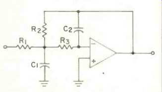
Fig. 1--Low-pass, multiple-feedback filter.
Figure 1 shows á low-pass multiple feedback fitter. The associated design formulas are:
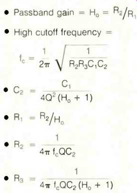
The usual procedure is to choose a likely value for C1, then calculate the values for the other components. If these values are not practical (the resistors often come out too large or too small), then choose another value for C1 and start over. This is tedious and frustrating, even with a scientific calculator.
Figure 2 shows the corresponding high-pass filter. Its parameters are:
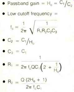
[The design procedure is similar to the low-pass filter's. ]
[A major advantage of the multiple-feedback filter is that it runs in inverting mode, reducing common-mode error and thus noise. ]
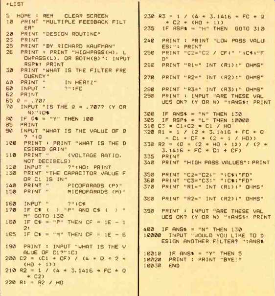
THE PROGRAM
Using the Filter
The filter should be buffered, since the input network could react unfavorably with the signal source. An inverting buffer is shown in Fig. 3; the result will be correct absolute phase, if the rest of the system is noninverting. The values of the resistors are not critical, but they must match; 5% or better tolerance is desired. The input impedance equals the resistor value chosen.
Any value between 10 and 100 kilohms will work well with the majority of modern audio circuits.
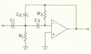
Fig. 2--High-pass, multiple-feedback filter.
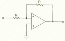
Fig. 3--Inverting buffer for use with filters.
The resistors for the filter should preferably be within the same range of values, though resistances as low as 1 kilohm or as high as 1 megohm are acceptable, if such values prove necessary to keep capacitor values reasonable. The capacitors should be plastic-film types or silver mica; ceramic discs and electrolytics are unacceptable. Ten-percent tolerance resistors will keep the response flat to within 1 dB for second- and third-order filters, though 5% tolerance is preferable.
Filter Order and Q
The order of a filter determines its rate of attenuation; multiple feedback via R2 and C2 makes this a second order circuit, with an attenuation rate of 12 dB/octave. Q is a dimensionless parameter that determines the "peakiness" of the filter's response near cutoff, The best value of Q for a second order filter is generally 0.707; this gives a "Butterworth" response.
The attenuation of third-order filters is 18 dB/octave, making them superior for high-pass and subsonic filters. For speaker crossover networks, third-order networks offer better phase coherency, smoother pressure response, less interference between drivers, and reduced demands on the tweeter. The proper value of Q for a third-order network is 1. The third-order network consists of the multiple-feedback filter with a simple first-order filter substituted for the inverting buffer of Fig. 3. Inverting first-order networks are shown in Fig. 4. The cutoff frequency is determined by the formula:
F= 1/2 π RC
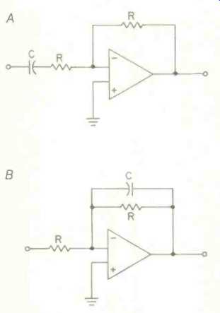
Fig. 4--Inverting first-order filters, high-pass (A) and low-pass (B).
This can easily be programmed in BASIC, an exercise that will be left to the reader. (Note lines 120 to 185 for determining how many zeros are needed for the capacitor value.) For a 2.5-kHz cutoff, R = 56 kilohms and C = 1,100 pF. There will be no problem driving a pair of these in parallel from a preamp if you want to bi-amplify your system.
Using the Program
Filter design with this program should be self-explanatory. The sample run shown here is for the design of a speaker crossover for bi-amplification, using a third-order network at 2.5 kHz. The high-pass values are calculated first; at a 2.5-kHz crossover frequency, Q = 1, with unity gain. A 1,000-pF capacitor (0.001 µF) is tried, but the value for R2 is a little high, so 1,800 pF is entered. Working with a 5% tolerance, 12 kilohms can be used for R1; R2 can be built up by 100 and 5.8 kilohms in series. This design is satisfactory.
Next, 1,800 pF is tried for the lowpass filter, but the resistor values are too high and are awkward to obtain. A value of 4,700 pF is better: 56 kilohms can be used for R1 and R2; the difference from the calculated value is less than 5%. A 27-kilohm resistor for R3 is a standard value. Capacitor C2 can be built up from 470 and 100 pF in parallel.
More information on different types of fillers you can build using multiple feedback circuits can be found in the many books available on active filter design.
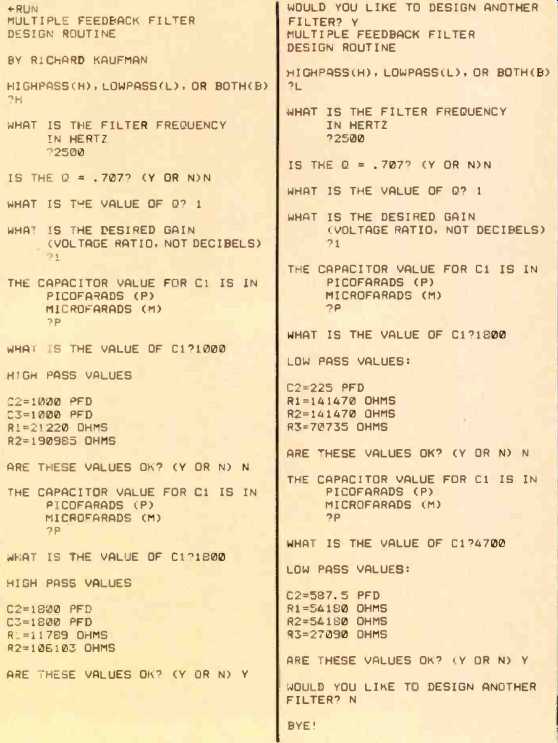
above: SAMPLE RUN
=============
(Source: Audio magazine, Nov. 1983)
Also see: Computer-Aided Audio Calculations (Nov. 1983)