BUILDING CASTLES IN THE BAND
Ever notice how a castle is built? There's usually a lot of wall, then at the top are the square wave-shaped formations so you can pour boiling oil or drop rocks on annoying people outside your castle. That architecture is referred to as crenellated battlements; the lower part where you pour the oil through is called the crenel, and the upper part protecting you is the merlon. If you think about it, it's definitely a digital design.
What does all this have to do with audio? Frankly, not much. But let's try to find the connection, however slim.
Last month we examined the nature of pulse code modulation (PCM) and concluded that it was a particularly slick kind of modulation, specifically well suited to audio digitization. The code that is an inherent part of PCM requires relatively little bandwidth to preserve the binary values of a waveform's amplitude at sample time.
And yet, lengthy deliberation might lead one to dark brooding. Why must the entire amplitude of the waveform be preserved when it is really only the changes from moment to moment which constitute musical information? Furthermore, when it comes to music, just how much will the amplitude change from moment to moment, especially when you're taking thousands of measurements each second? The idea dawns that perhaps only the difference from one sample to the next has to be stored to completely characterize the original waveform.
Differential pulse code modulation (DPCM) accomplishes exactly that. To reduce redundancy and thus the bandwidth required to store data, only the difference between adjacent pulse amplitude modulation (PAM) samples is recorded, forming a differential pulse amplitude modulation (DPAM) signal. On the decoding side, the pre sent sample value is regenerated by using the past value plus the received difference value. To increase efficiency, the present value may be estimated by using a prediction filter: A tapped delay line can examine many past samples and arrive at a safe guess for the value of the present sample. Such a device is called a transversal filter (the same design used in oversampling CD players) and is shown in Fig. 1.
The upshot is that when the difference from one DPAM value to the next is relatively small, a small number of quantizing steps are required to en code the DPCM signal. The bandwidth of the DPCM is thus much smaller than that of the equivalent PCM signal. Of course, the success of the technique hinges on the supposition that the differences from sample to sample will be small. To ensure this, a higher sampling rate is used, because the faster you sample, the smaller the difference from sample to sample.
Given a fast enough sampling rate, DPCM successfully reduces the number of quantizing steps needed to en code an audio waveform. And given a good thing, the natural urge is to take it all the way. Delta modulation (DM) is the limiting case of DPCM, in which the quantized DPAM signal is binary. In other words, only one bit is used to quantize the waveform. That leads to interesting consequences; for example, ND and D/A conversion are not needed, since the data word is only one bit long.
A complete delta-modulation system is shown in Fig. 2. The encoder compares its past approximation to the present input DPAM value and generates a one-bit correcting word at sample time; in other words, the system determines if its error is positive or negative, and correspondingly moves its next value up or down one increment, always closer to the present value. That one bit is all that is needed to record the signal; it simply documents whether the signal amplitude went up or down during the last sample interval. As shown in Fig. 3, that one bit tracks the signal, riding along the top of the analog waveform. At the decoder, the DM data is converted back into an analog signal. The only element needed is an integrator to smooth the correction data.
As you might expect, delta modulation is a fairly inexpensive way to en code data. In addition, it offers excellent error-correction performance. In a linear PCM system, an incorrect most-significant bit (MSB) would result in a massive glitch. However, in delta modulation there is no MSB, so the effect of a bad bit is limited to the amplitude difference of one increment.
Only one flaw limits widespread application of delta modulation. Take a close look at Fig 3. See the part of the curve where the waveform takes off while the delta modulation signal lags behind? That is the fatal flaw-slope overload. Delta modulation is successful only when it can track the input waveform. An audio signal is filled with fast-moving transients; thus only a very fast sampling rate would permit the DM data to keep up, given a quantizing step size small enough to yield useful resolution. Linear PCM balances word length and sampling rate for a successful result; DM attempts to do it all with sampling rate alone.
A single sign-changing bit simply cannot track a complex waveform; slew-rate limitations yield transient distortion. Therefore, DM's applications are limited. For example, one DM system used for speech transmission must sample at 17 MHz to maintain even lo-fi quality. From an informational standpoint, we can see that things are indeed out of whack; specifically, the bandwidth of the system is being wasted in an audio application. The Nyquist Theorem tells us that a sampling frequency of 17 MHz would permit en coding of extremely high frequencies, but even the most golden of ears has little use for a frequency response of 0 Hz to 8.5 MHz . . . .
However, DM is too nifty to discard. For instance, because of the high sampling rate, no brick-wall filters are required; a gentle filter with low phase shift can roll off the input well before the half-sampling frequency. To rescue the technique, designers have developed various schemes for solving the basic limitation of slope overload. The goal is to form a system with a reasonable sampling rate capable of handling audio waveforms.
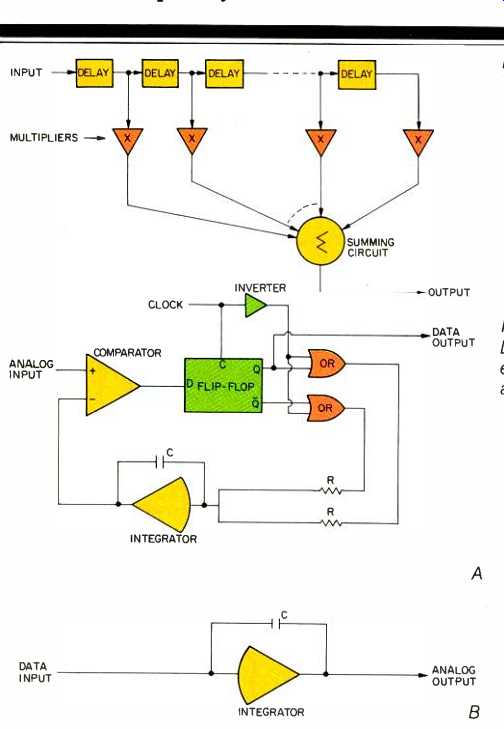
Fig. 1--Transversal filter. Fig. 2--Delta-modulation encoder (A) and decoder
(B).
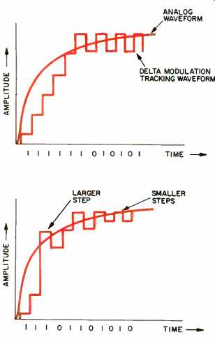
Fig. 3--Delta-modulation tracking; note slope overload from first to fifth
step. Fig. 4--Adaptive delta-modulation tracking; note variable step sizes,
used to avoid slope overload.
Adaptive delta modulation (ADM) tackles the problem head-on. The quantization step size is made variable (Fig. 4): Large steps are used for fast-changing waveforms, so the system can keep on track, while small steps are used for slowly changing wave forms, to maintain resolution. Various algorithms may be used to select proper step size. In general, alternating ones and zeroes at the encoder's output indicate proper tracking, so small quantizing increments are selected.
When continuous ones or zeroes are present, the waveform is clearly on the move, and larger steps are selected.
With this approach, a price is paid in increased hardware complexity. The decoder must constantly figure out what step size the encoder has selected. The two must be synchronized, using the data itself as the common de nominator. Also, it is difficult to change step size quickly enough to keep track of audio transients. Moreover, certain conditions such as simultaneous high frequencies and high amplitudes can produce modulation noise, in which the noise floor becomes a function of the signal itself. This artifact is difficult to remedy because a fixed level of dither is ineffective with varying increment sizes.
Another approach is companded predictive delta modulation (CPDM).
Rather than vary step size, the signal's amplitude itself is varied to fit a fixed step size. A compander is used to control the amplitude of the audio signal (lowering its slew rate) so that the fixed-step-size delta modulator will not be overloaded. In some designs, to ensure tracking accuracy, a special transient detector is used to provide extreme compression of fast-changing audio transients.
With a little help, either from adapting step sizes or from companding, delta modulation can be used for audio digitization applications. In one current incarnation, a CPDM system samples at 640 kHz, a much more reasonable frequency than the 17 MHz discussed earlier, and yields full fidelity.
When it's all boiled down, the principal specification, data rate, is surprisingly similar for audio PCM and DM systems. A 16-bit, fixed, linear PCM system sampling at 44 kHz requires a data rate of 704 kilobits/S per channel, while CDPM produces 640 kilobits/S about the same amount of information either way, despite their radically different methods.
Castle walls? Crenels and merlons? It's obvious--PCM is like the entire height of the wall itself, while delta modulation is just the crenellations themselves. I told you the connection was pretty slim.
(adapted from Audio magazine, Nov. 1985)
= = = =