by Ken Kantor
[Ken Kantor is president of Product Design and Evaluation Services, in San Francisco, and is co-founder of speaker manufacturer Now Hear This.]
It's no great secret that computers have impacted the field of loudspeaker design in a big way. Remember all those corny photos of very serious-looking engineers looking fiery seriously at computer screens aglow with 3-D plots and response curves? Well, the days are gone when only the biggest and richest manufactures could advertise, with any justifiable pride, their use of computerized design techniques. The news now is that personal computers are entering the picture. As processing capabilities expand, powerful speaker design software is becoming available for the IBM PC family. Programs for crossover, enclosure, and driver design are providing fast and accurate results to profess-on al and amateur speaker designers alike.
Probably the best way to illustrate the role that personal computers play in loudspeaker design is to develop a working speaker system of our own, step by step. We will confront the kind of design decisions that professional designers face every day, and call on the personal computer to help support these decisions. The reader is encouraged to construct the loudspeaker we develop; the result will be at least the equal of high-quality commercial offerings.
Computers influence each step of the speaker design process, from beginning to end. For example, to initiate the development of any new loudspeaker system, decisions must be made about general system architecture ... how big, how many drivers, what type of enclosure, etc. These decisions are heavily influenced by the designer's individual philosophy, and by particular application requirements, such as size or price constraints. At this early stage, the computer is useful for running the kind of tedious, repetitive analyses that are necessary to cull through the thousands of available driver types in order to zero in on the most suitable units. A computer can also help the loudspeaker engineer quickly perform "what-if" tests to study the interaction of drivers with each other and with enclosures.
Next, the designer must plow through the tedious mathematical procedures required to implement the real details of the speaker. Exactly how does the cabinet match the chosen woofer? What happens when the crossover network interacts with the tweeter's impedance curve? How many grams of polyester fiber should be used inside the enclosure? These are among the many questions professional designers must answer for each and every new loudspeaker. Because calculations which used to take hours now take but moments, a credible prototype can be specified far more quickly, and with greater success, than even a few years ago.
Final product refinement can take months and can involve literally hundreds of recalculations of box "tunings" and crossover responses. The human ear is inevitably the ultimate arbiter in refinement decisions, so listening tests are an essential part of the final design phase. By rapidly weeding out blind-alley modifications, computers have actually increased the amount of time most designers spend listening to final prototypes. Freeing engineers and designers from the need to calculate for a day in order to listen for an hour, allows much more time to be spent on well-focused and productive listening.
In case you are worried about automation heralding an era of bland, homogenous speaker sound, remember that computers can't really design loudspeakers. First off, speakers are frighteningly complex systems. Accurate, full-range prediction of frequency, time, and polar response are beyond even the largest computers available to engineers. Even more important, nobody seems to know how to put into words and numbers what it is that a good speaker is supposed to do.
There are as many theories about the relationships between measured factors as there are designers. So computers remain tools, helping designers to achieve what they want and to understand what they hear.
A Design of One's Own
The question of where to begin a speaker design is difficult to answer definitively. One could, for example, develop an entire system design around some particular crossover capacitor value deemed to have mystical sonic properties. Or one might, perhaps, attempt to develop a full-range system using a single 18-inch cone woofer. Anything is possible, and silly things have been tried.
The general design approach we will follow is outlined in Table I. Probably the most useful point of embarkation is a decision about how many drivers are to be used, considering what the system application is to be. As a design exercise, a two-way system makes good sense. It enables one to realize excellent sound from an affordable configuration, without getting bogged down in overly complex crossover issues. Faced with the choice of starting with a box and designing the drivers, or vice versa, we'll go for the latter; that's because few hobbyists construct their own drivers.
In a two-way system, a 6 1/2-inch woofer is a good choice. It's a popular size, and one that works well in an enclosure of moderate volume. Finding a driver with good midrange response, together with a reasonable amount of bass, will be relatively easy. As we get started on woofer selection, we will gradually gain all the information we need to choose an appropriate tweeter for the system.
=====================
Table I-Steps in the design process.
1) Choose overall system configuration, size of woofer, number of drivers, etc.
2) Choose vented or sealed system
3) Select actual woofer
4) Measure woofer's Thiele-Small parameters
5) Design and construct enclosure
6) Test woofer frequency response in enclosure
7) Choose crossover point
8) Choose tweeter
9) Measure tweeter frequency response
10) Design and construct crossover network
11) Measure response of complete system
12) Conduct listening tests
13) Revise crossover network as necessary
14) Finalize construction details
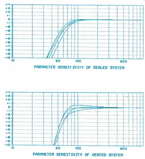
Fig. 1---How performance of sealed and vented speaker systems is affected
by small changes in woofer parameters.
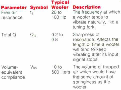
Table II--Important Thiele-Small parameters.
(top) Fig. 2--Computer-predicted response of Tonegen 16K65 woofer in 5-, 10-,
and 20-liter sealed enclosures. (above)
Fig.
3--Computer-predicted response of Tonegen woofer in 10-liter sealed enclosure.
Note the gentle peak just above the cutoff point (see text).
======================
The Low-Down on Woofer Parameters
The primary role of a loudspeaker box, besides physically supporting the drivers, is to prevent the woofer's anti phase rear wave from cancelling the desired low-frequency output from the front of the speakers. This role leads to a close interdependence between woofer and cabinet. The woofer/enclosure relationship is the essence of low frequency loudspeaker design. To get a handle on things, it is necessary to understand the mechanical, electrical, and acoustical properties of woofers.
The behavior of any given woofer can be partially characterized by a set of numbers generally called "low-frequency parameters." These parameters measure factors like cone weight and suspension springiness, and can be used to predict how a woofer will respond to input signals and how it will be affected by a speaker box. Parameters are most useful for predicting the low-bass frequency response of the speaker; they only hint at upper-range response, and at the issues of power handling and distortion. While woofers with identical parameters might have very different frequency response curves at the middle and top of their ranges, it is a safe bet that they will have very similar curves at the lowest frequencies, where the enclosure has the greatest influence.
In the early '70s, the speaker theorist Richard H. Small, expanding on the earlier work of Beranek, Thiele, and others, began an ambitious effort to organize and simplify the problem of low-frequency loudspeaker design. He suggested the use of a particular set of parameters, now commonly called "Thiele-Small Parameters," for use in developing both sealed and vented enclosures. In fact, Small suggested that the behavior of any piston woofer can be reduced to only three numbers, for purposes of calculating low-frequency response and box interaction (Table II). Small's work was a major advance in saving time and increasing accuracy.
But the mathematical effort required to measure and derive the necessary parameters, and to calculate and display their effects, still prohibited much exploration of alternatives and possibilities in a new design. The automation of Thiele-Small computations was one of the first tasks speaker engineers gave to their computers. Now there are a number of commercially available speaker design programs, selling at anywhere from under a hundred to several hundred dollars. Scientific Design Software, a Southern California firm, offers a very useful and affordable software package to help measure drivers and to perform Thiele-Small calculations on a personal computer.
Called "Computer-Aided Speaker Design" (CASD, for short), the package maintains extensive files of the offerings of driver manufacturers, and can also assist with basic crossover design tasks. CASD will help us as we progress, generating the enclosure-design graphs.
To Vent or Not to Vent?
For any given woofer, there is one, and only one, enclosure volume that will yield flat bass response in a sealed acoustic suspension configuration.
This volume must be known before a speaker is constructed, as there is no way to easily adjust the response after completion. Mainly for this reason, amateur speaker builders have tended to prefer vented systems, which can be "tuned" after completion by adjusting the area and length of the vent. However, with the help of our computer, we can determine the correct sealed-box size initially, and there are two reasons why we might wish to use this approach. The first is that sealed systems are better behaved when driven by signals below their operating frequency range. In a larger system, this wouldn't be as serious an issue, but with a 6 1/2-inch driver, the lowest musical notes will certainly fall below the woofer's capability.
The second reason for going with a sealed approach in a home-built system is the effect that driver and box variations have on the final response.
Sealed systems are generally more tolerant of the errors that can arise when determining a driver's parameters, and of the variations from one production driver to the next. To show this, we can use our computer to calculate and plot the different response curves that result when various Thiele-Small parameters depart from the values around which an enclosure has been designed. Figure 1 compares two speakers in this manner; one of the speakers is vented and the other is sealed.
When the parameters are correct, the systems have a very similar response, maximally flat with a bass cutoff just below 60 Hz. As the parameters drift, by an amount not all that unusual, the sealed system can be seen to vary most below its bass cutoff, where the effect on tonal balance will be reduced. In contrast, the vented system might exhibit significant changes in its overall balance, as the critical bass frequencies between 80 and 200 Hz change by almost 2 dB.
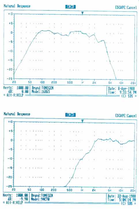
(top) Fig. 4--Measured performance of the Tonegen woofer in a test chamber.
Compare to Fig. 3. (above) Fig. 5--Measured response of the tweeter.
A Choice Woofer
For this construction project, woofers from several of the top driver manufacturers in the U.S. and abroad were considered. Important requirements were defined to be:
1) Thiele-Small parameters appropriate for flat bass response in a sealed box of roughly 10 liters,
2) Good, clean response up through several kHz, and
3) Consistent performance from unit to unit.
The recommended unit is a 6 1/2-inch driver made by Tonegen of Japan, from their 16K65 family. As well as meeting the criteria set forth above, the 16K65 has low distortion and a well controlled, natural roll-off that will simplify our crossover requirements.
Woofer parameters are most commonly determined based on data obtained from the driver's impedance curve. This is generally done in "free air" (no enclosure), using an unmodified driver, but certain parameters are most accurately calculated from the impedance changes seen when a driver is modified by adding mass to its cone or by placing it in a test enclosure whose volume is precisely known. Of course, many driver suppliers provide a list of important parameters for their products, but the possibility of error, and the effect that small test details can have on results, mean that most professional speaker designers use published specs for general selection only. Exact parameter determination is always done in the designer's lab.
The CASD software package includes a subprogram, called "DATA," used to help calculate parameters from a driver's impedance curve. Table Ill shows the results of a DATA program test on the 16K65 woofer we will be using. All the engineer need do is connect the driver to impedance measurement equipment and enter into the computer the information that DATA requests. At one point in the procedure (which takes about three minutes with advanced measurement equipment), the impedance must be recalculated with a small weight placed on the cone, or with the driver in a box of known volume. This is necessary to calculate the compliance, or springiness, of the driver.
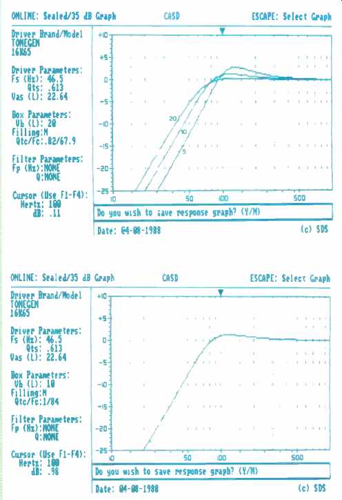
Of all the parameters displayed by DATA, only three-fs, Q_ts, and Vas are necessary to design an appropriate enclosure. By typing these three parameter values into the CASD program, we can easily generate a family of curves showing the predicted response of the woofer in 5-, 10-, and 20 liter enclosures (Fig. 2). The entire process of going from an unknown driver to a predicted response takes, including setup, perhaps 10 minutes. A far cry from the many hours an engineer with a calculator must spend! The 5-liter enclosure is clearly too small, resulting in reduced bottom-end response and a peak in the mid-bass.
The 20-liter enclosure exhibits a relatively flat response and the best deep bass. For a 6 1/2-inch woofer, the 10-liter enclosure, with a bass cutoff of 62 Hz, is probably the best choice (Fig. 3). Almost all small loudspeaker systems are designed to be underdamped, with a slight peak near the bass cutoff point. If this peak is kept small--less than 3 dB or so-it will not add boominess, and will help achieve a natural tonal balance by complementing an extended top end. Maximally flat response on systems that have a bass cutoff above about 50 Hz almost always yields a speaker that subjectively is overly bright.
Our next step will be to construct a 10-liter box and test the actual acoustic response of our system. There are two important questions we can answer with this test: "Are our computer predictions correct?" and "What is the upper frequency limit for good response from our woofer?" Figure 4 shows the curve of our woofer in a test chamber. To a practiced eye, there is good correlation with the predicted low-frequency response; the bass cutoff frequency and degree of peaking are just about what CASD described. At higher frequencies, out of the range of Thiele-Small estimation, the 16K65 is flat within ± 1 dB or so, up to its high-end limit.
Considering that this is a high-resolution, non-smoothed plot, that represents excellent performance.
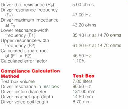
Table IIIA-Measured woofer parameters entered into CASO program.
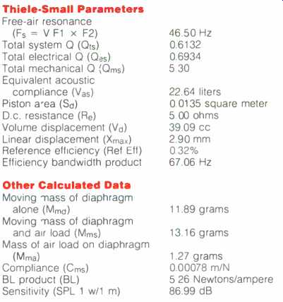
Table IIIB-Woofer data calculated by CASD.

Fig. 6--Crossover network, with a first-order low-pass titter for the woofer
and a second-order high-pass filter for the tweeter.
Resistor R1 is for use in matching tweeter and woofer output levels.
Look, Listen, then Crossover
Because woofers can typically handle much more power than tweeters, it is tempting to raise the crossover frequency of a two-way design as high as possible. This sends more energy to the woofer and less to the tweeter.
There are two basic factors that restrict how high a woofer can be run. First is the question of directivity. All piston drivers begin to beam their output into a narrow angle as frequency increases. The larger the driver, the lower the frequency at which this happens, regardless of the individual frequency response of the driver. This places a limitation on how high we can take our 6 1/2-inch woofer-about 4 kHz, as an approximation.
The second issue to consider is how high in frequency a particular woofer can maintain an ample and smooth sound output. The 16K65 Tonegen woofer starts a gradual roll-off above 2 kHz, with a rapid roll-off above 3.5 kHz.
This suggests opting for a crossover point of about 3 kHz, in line with directivity considerations. Since all crossovers necessitate a region where both woofer and tweeter are overlapping to some degree, the reduced woofer output above 2 kHz, but below our crossover point, will provide a good transition range and will help avoid a midrange bump. Above the crossover point, our electrical filter will combine with the woofer's natural response to provide a very fast cutoff. Now we can select a tweeter and begin a theoretical network design. Precise determination of the final crossover characteristics will be left until we can measure and audition the complete system.
Referring back to Table III, we can see that the DATA program estimated our woofer's sensitivity at just about 87 dB/W/m. It is very difficult to balance driver levels exactly before building a test system, so it is wise to consider ways to adjust levels using the crossover network. Since padding down the output of a tweeter to match a woofer's output is much more practical than the opposite approach, we should select a tweeter that has a sensitivity of at least 89 dB, to be safe. The Tonegen 94C70 is a good unit, and one that meets our frequency and sensitivity requirements. (The response of this unit is shown in Fig. 5.) This 1-inch dome tweeter will have no problem with a 3 kHz crossover point.
A first-order (6 dB/octave) filter will work well on the woofer because it has a rapid and well-behaved natural roll off. For maximum power handling and the smoothest midrange, a second-order (12 dB/octave) filter will be used on the tweeter. (The network topology chosen is shown in Fig. 6.) A resistor is included in series with the tweeter, so that the tweeter's output level can be trimmed to exactly match that of the woofer.
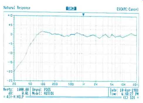
Fig. 7--On-axis frequency response of the completed system, measured at
1 meter.
==============
Software of Note
Computer Aided Speaker Design (CASD)
General purpose Thiele-Small enclosure design; extensive driver library files; basic crossover tasks; miscellaneous speaker design utilities; includes "DATA" parameter calculation program.
Company Address: Scientific Design Software, Attn: Ted Telesky, P.O. Box 3248, Chatsworth, Cal. 91313; (818) 718-1201. Price: $199.95.
Computer Aided Crossover Design (CACD)
Advanced crossover network design; driver impedance modeling; system response prediction; sophisticated electrical network analysis and optimization.
Company Address: Same as above.
Price: $349.95.
Loudspeaker Enclosure Analysis Program (LEAP) Advanced enclosure design and analysis; handles multi driver and multi-enclosure systems; modeling beyond Thiele-Small limitation; output includes phase, delay, impedance, etc.
Company Address: CNS Electronics, Attn: Chris Strahm, P.O. Box 42389, Portland, Ore. 97242.
Price: $199.
==============
Crossover network design is perhaps the most misunderstood aspect of amateur speaker construction. The complex impedance curves of loudspeaker drivers and the interaction between electrical and acoustical responses make cookbook crossover design a myth. Many hobbyists design circuits that assume drivers look like resistors or purchase prefab crossovers based on the same assumption.
If either of these approaches gets within two miles of the desired response, it is a rare accident indeed. Accurate design requires many hours of measurement, calculation, and refinement.
A new offering from Scientific Design Software, the creators of CASD, is useful in reducing the amount of trial and error involved in network development.
Called CACD (you can guess what for), the program processes detailed descriptions of actual impedances and responses, applying advanced mathematical optimization techniques to adjust the values of a user-entered circuit. The real power of CACD is that it can handle just about any kind of circuit and driver accurately. There is no need to work with standard designs.
Tables IV and V show examples of some of the kinds of data CACD processes as input and output, respectively. To illustrate the evolution of a simple crossover through four phases, from concept to final design, Table VI compares specific crossover component values:
1) Derived from a "cookbook" approach,
2) Suggested by CACD,
3) Refined by measuring electrical and acoustical responses, and then
4) Exhibited in the ultimate version, refined by listening tests.
The Solution
Listening tests with a variety of program material revealed a slight excess of upper-midrange energy. This was manifest as a slight harshness on some recordings and particularly affected female vocals. This prompted a new round of detailed measurements, which indicated that perhaps the tweeter output was extended too low in frequency. Minor adjustments to the tweeter crossover point smoothed out the measured and perceived response. Overall balance between woofer and tweeter was judged to be subjectively correct.
Figure 7 shows the measured response of the system at 1 meter, on axis. Measurement data above 300 Hz was obtained in a listening room, using FFT impulse techniques. Data below 300 Hz was achieved using a near field method. The low-frequency response shown should be representative of placement on stands at least 1 meter from the side and rear walls.
Placement closer to room boundaries would increase deep bass output.
As is good practice with any new design, an impedance curve was run to assure that the system did not pre sent an unduly difficult amplifier load.
Average impedance ran well over 8 ohms, with a minimum of 6 ohms at 190 Hz ... a very easy load.
In our next installment, we'll discuss the construction of our loudspeaker enclosure, concentrating on the general issues involved.
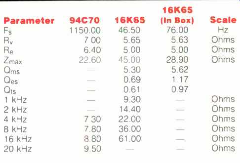
Table IV-Input data tor CACD program.
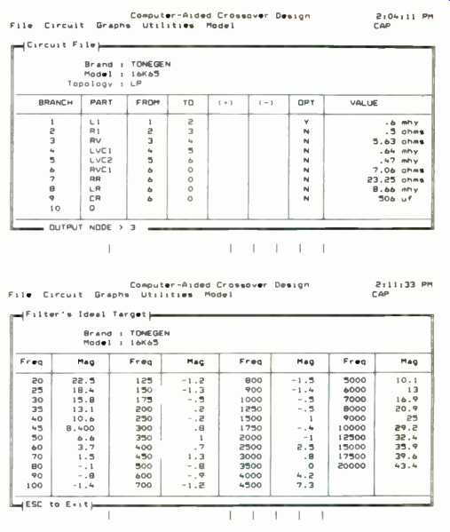
Table V-Output data horn CACD program.

Table VI-Crossover network values.
(adapted from Audio magazine, Nov. 1988)
Also see: Speakers by Design by Ken Kantor -- Part 2 (Dec. 1988)
An Informal History of Solid-State Amps (June 1988)
= = = =