
Manufacturer's Specifications:
Rated Power: 35 watts per channel into 4, 8, or 16 ohms, from 20 Hz to 20 kHz.
THD: 0.25% at full rated power, less at lower output levels.
IM Distortion: Less than 1% at up to 30 watts continuous per channel into 4, 8, or 16 ohms, with any combination of test frequencies.
Frequency Response: ±0.5 dB, from 20 Hz to 20 kHz, at rated power level.
Hum and Noise: At least 90 dB below 30 watts, at all frequencies.
Damping Factor: Greater than 15.
Dimensions: 13 in. W x 9 in. D x 7 in. H (33 cm x 24.1 cm x 17.8 cm). Weight: 35 lbs. (15.9 kg).
Price: $995 in black, $1,095 in chrome.
Company Address: 125 Cabot Ct., Hauppauge, N.Y. 11788, USA.
The original Dynaco Stereo 70, produced when tubes were still the norm, probably outsold every other tube amp by a very considerable margin. The emergence of this new version is evidence of the present-day renaissance of high-fidelity tube electronics. The Dynaco Stereo 70 Series II came about through the efforts of John Peterson of Sound Values (formerly Stereo Cost Cutters), the company that has been selling Dyna replacement parts and kits of some Dynaco products, and Bob Rapoport, a 22-year veteran of the audio industry. Rapoport had long dreamt of resurrecting the Dynaco product line. A deal was struck with the Panor Corporation, a maker of automotive and marine audio systems, and with Leo David, a chain of stereo shops that had ended up owning the Dynaco name. Several consultants were brought in to modernize the design of the old Stereo 70, and the end result is the product under review.
The new version, while retaining the original overall dimensions and what's stated to be the same output transformer design as in the original, differs from the earlier design in several ways that can impact the way the unit measures and sounds. Physically the amp at first glance looks like the old Stereo 70, but a closer look reveals some of the changes. First, the speaker-output screw terminals have been replaced by four five-way binding posts for each channel. These are intelligently arranged; the 4and 8-ohm terminals flank the ground connection, allowing dual-banana plugs to be used for connecting most speakers. (The 16-ohm terminals, placed out beyond the 8-ohm ones, are too far from the ground terminal for dual-banana plugs, but 16-ohm speakers are fairly rare these days.) The old octal sockets that provided filament and plate power to Dynaco (and some other) preamplifiers have been eliminated, the input phono jacks are of better quality and gold plated, and the cheap slide switch for power on/off has been replaced with a more modern rocker. Best of all, the old "Biaset" method of setting bias with a voltmeter has been updated.
Each channel's bias pot is now accessible through the front panel and is flanked by a pair of LEDs that illuminate equally when the control is properly adjusted. Internally, the biggest change in construction is from a small p.c. board and a lot of point-to-point wiring to a single, large p.c. board that carries all the major components except the transformers.
The overall circuit is about like the original except that the input tube has been replaced with a similar but more easily attainable tube. One major philosophical difference in the new design is a change in the internal open-loop compensation scheme and the addition of passive input filtering to limit the signal bandwidth to about the audio range. This should improve distortion at the frequency extremes and possibly reduce transient intermodulation distortion. However, with bandwidth limited at the input, Dynaco has also apparently removed the original design's high-frequency stabilization network, a capacitor and resistor in series from the plate of the first tube to ground. This network's purpose was to reduce open-loop gain at high frequencies so as to produce stable high-frequency behavior with negative feedback applied. The schematic of the new version states that this network is "not used in some assemblies." In an attempt to reduce what probably was negligible transient inter modulation distortion in the original design, the designers of the Stereo 70 II may have caused some problems that we shall look at in the "Measurements" section. Another consequence of the input band-limiting network is that the amp should be driven from a source impedance of less than 2 kilohms so as not to further reduce the high-frequency bandwidth. (This won't be a problem for most users, who drive their amplifiers from preamps, but may be a problem for a few nuts like me who prefer to use a passive attenuator to drive their power amps.) Another change in the Series II is that the overall negative feedback loop is derived from the more often used 8-onm tap on the secondary of the output transformer rather than the 16-ohm tap used in the original.
In the power supply, the transformer has been beefed up and made with a dual primary (permitting easy change for overseas a.c. mains), solid-state rectifiers have replaced the 5AR4 tube rectifier, the trouble-prone selenium rectifier in the bias supply has been replaced with a more reliable modern silicon unit, and the main high-voltage filter capacitance has been increased to about three times its original value. These changes would tend to increase both transient and steady-state power output compared to the original.
Measurements
Voltage gain into 8-ohm loads on the 8-ohm taps was found to be 22.3 dB for both channels, with a corresponding IHF sensitivity of 217 mV. This is impressive gain matching for a tube power amplifier Frequency response at the 1-watt level was measured for open-circuit, 8-ohm loads, and 4-ohm loads on the 8-ohm tap. This is shown in Fig. 1 for the right channel; the slight peaking seen between 150 and 200 kHz is an aberration not present in the left channel. Easy to see here is the bandwidth limiting caused by the input filter; the relatively close spacing of the curves indicates a relatively low output impedance. Data taken from these curves yield an approximate output impedance of 0.6 ohm.
Square-wave response for the Stereo 70 II's left channel is shown in Fig. 2. The top trace is for a 10-kHz signal into 8 ohms on the 8-ohm tap. Rise-and fall-times aren't too swift.
They are on the order of 16 µS, predominantly a consequence of the input filtering. A 2-uF capacitance was added to the 8-ohm load in the middle trace. Here the waveform is quite altered, more so than on other power amplifiers. With the same 2 µF and 8-ohm load, the ringing on a 1-kHz square wave (not shown) only decayed by about 50% within the half-cycle time of the 1-kHz signal (500 µS). This is marginally stable performance. In fact, under the same circumstances, the right channel outright oscillated. The aforementioned high-frequency stability network components are provided for on the p.c. board, and in fact, the capacitor is present but the resistor is left out. Adding an 18-kilohm resistor, and hence activating the stability network, caused the amplifier to behave properly. The 1-kHz square wave signal then damped out after perhaps one cycle of ringing, and the 10-kHz waveform looked much more like that from other amplifiers. I think taking this network out was a mistake that may have adverse sonic consequences in some users' systems.
The bottom trace of Fig. 2 is for a 40-Hz signal. The severe tilt shown is caused by the input high-pass filter (approximately 19 Hz, first order). Total harmonic distortion plus noise for a 1-kHz signal, and SMPTE-IM distortion, are shown in Fig. 3 for 8-ohm loading on the 8-ohm tap for the left channel. Distortion is impressively low in both channels.
Load tolerance is pretty good: The amp delivers full power (though with higher distortion) when loaded with half the rated output-tap impedance. With a load of twice the tap impedance, distortion is lower, but attainable output power is about half that available with loads of half to full rated impedance. Total harmonic distortion as a function of frequency and power is plotted in Fig. 4, while Fig. 5 shows the spectrum of distortion residue at 1 kHz for an output of 10 watts into an 8-ohm load on the 8-ohm tap. Although the dominant harmonics are low-order, as can be seen, plenty of higher order components are present though at much lower levels.
For comparison. I borrowed an old Stereo 70 that was in pretty good shape. I changed the output tubes and generally cleaned and tuned it up to assure proper operation. The measured distortion was about 10 times higher in the original unit than in this new design. I think that this is mainly due to the different front-end tube used in the Series II and, possibly, to worn-out 7199 front-end tubes in the old Stereo 70. Not having any more 7199s to try in the old unit, I wasn't able to verify this. Bandwidth, stability, and output impedance of the old Stereo 70 were similar to the new design's when its input network was removed and the high-frequency stability network was connected. Power output of the new version was about 4 to 6 watts higher at the onset of clipping.
Getting back to the new Series II, I tested damping factor with the stability network out, as delivered, and found it quite uniform over the audio range. It was about 13.5 for the left channel and 14.0 for the right channel, as measured on the 8-ohm tap.
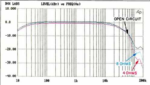
Fig. 1--Frequency response as a function of loading, at 8-ohm tap.
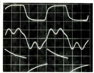
Fig. 2--Square-wave response, measured at 8-ohm tap, for 10 kHz with 8-ohm
load (top), 10 kHz with 2-µF capacitance across 8 ohms (middle), and 40 Hz
with 8-ohm load (bottom). Scales: Vertical, 5 V/div.; horizontal, 20 µS/div.
for 10-kHz traces, 5 mS/div. for 40 Hz.
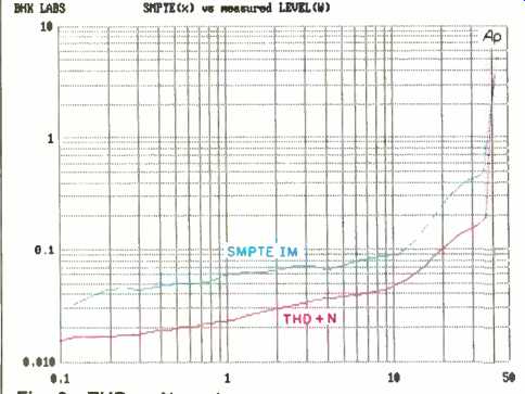
Fig. 3--THD + N, and SMPTE-IM distortion, vs. output power for 8-ohm load
on 8-ohm tap.
Output noise as a function of measurement bandwidth, along with the IHF S/N ratio, is presented in Table I. Hum and line harmonics account for the difference between the readings for a bandwidth of 400 Hz to 22 kHz (made with a 400-Hz high-pass filter that screens out hum frequencies) and the readings made wideband or from 22 Hz to 22 kHz. quite altered, more so than on other power amplifiers. With the same 2 µF and 8-ohm load, the ringing on a 1-kHz square wave (not shown) only decayed by about 50% within the half-cycle time of the 1-kHz signal (500 µS). This is marginally stable performance. In fact, under the same circumstances, the right channel outright oscillated. The aforementioned high-frequency stability network components are provided for on the p.c. board, and in fact, the capacitor is present but the resistor is left out. Adding an 18kilohm resistor, and hence activating the stability network, caused the amplifier to behave properly. The 1-kHz square wave signal then damped out after perhaps one cycle of ringing, and the 10-kHz waveform looked much more like that from other amplifiers. I think taking this network out was a mistake that may have adverse sonic consequences in some users' systems.
The bottom trace of Fig. 2 is for a 40-Hz signal. The severe tilt shown is caused by the input high-pass filter (approximately 19 Hz, first order). Total harmonic distortion plus noise for a 1-kHz signal, and SMPTE-IM distortion, are shown in Fig. 3 for 8-ohm loading on the 8-ohm tap for the left channel. Distortion is impressively low in both channels.
Load tolerance is pretty good: The amp delivers full power (though with higher distortion) when loaded with half the rated output-tap impedance. With a load of twice the tap impedance, distortion is lower, but attainable output power is about half that available with loads of half to full rated impedance. Total harmonic distortion as a function of frequency and power is plotted in Fig. 4, while Fig. 5 shows the spectrum of distortion residue at 1 kHz for an output of 10 watts into an 8-ohm load on the 8-ohm tap. Although the dominant harmonics are low-order, as can be seen, plenty of higher order components are present though at much lower levels.
For comparison, I borrowed an old Stereo 70 that was in pretty good shape. I changed the output tubes and generally cleaned and tuned it up to assure proper operation. The measured distortion was about 10 times higher in the original unit than in this new design. I think that this is mainly due to the different front-end tube used in the Series II and, possibly, to worn-out 7199 front-end tubes in the old Stereo 70. Not having any more 7199s to try in the old unit, I wasn't able to verify this. Bandwidth, stability, and output impedance of the old Stereo 70 were similar to the new design's when its input network was removed and the high-frequency stability network was connected. Power output of the new version was about 4 to 6 watts higher at the onset of clipping.
Getting back to the new Series II, I tested damping factor with the stability network out, as delivered, and found it quite uniform over the audio range. It was about 13.5 for the left channel and 14.0 for the right channel, as measured on the 8-ohm tap.
Output noise as a function of measurement bandwidth, along with the IHF S/N ratio, is presented in Table I. Hum and line harmonics account for the difference between the readings for a bandwidth of 400 Hz to 22 kHz (made with a 400-Hz high-pass filter that screens out hum frequencies) and the readings made wideband or from 22 Hz to 22 kHz.
In practice, hum was inaudible with my setup. Interchannel crosstalk was more than 80 dB down over most of the audio range, decreasing to about 70 dB at 20 kHz.
Measuring dynamic headroom with 8-ohm loading on the 8-ohm taps yielded a momentary reading of 39 watts, for a headroom figure of 0.47 dB. Steady-state power output at visual onset of clipping was about 37 watts, for a clipping headroom of 0.24 dB. The above measurements were made with a line input of 120 V a.c.
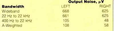
Table I--Output noise. The IHF S/N ratios were 88.3 dB for the left channel
and 93.7 dB for the right channel.
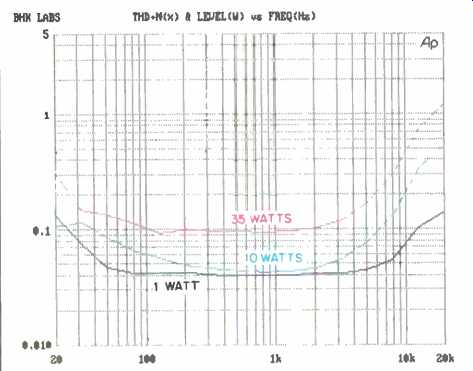
Fig. 4--THD + N vs. power and frequency for 8-ohm load on 8-ohm tap.
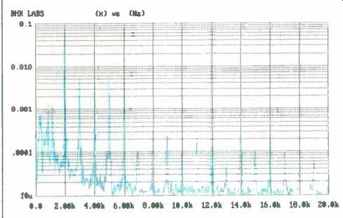
Fig. 5--Distortion spectrum for 1-kHz signal at 10 watts out into 8-ohm
load on 8-ohm tap.
Use and Listening Tests
Ancillary equipment I used when evaluating the sonic properties of the Dynaco Stereo 70 Series II included the following signal sources: An Oracle turntable fitted with a Well Tempered arm and Spectral Audio MCR-1 Select MC cartridge feeding a Vendetta Research SCP-2B pre-preamp; a Krell Digital MD-1 CD transport feeding either a VTL Reference, VTL Straight-Line, or PS Audio UltraLink D/A converter; a Nakamichi 250 cassette deck and ST-7 tuner, and a Technics 1500 open-reel recorder. Preamplifiers used included a Coda Technologies FET 01, a Quicksilver Audio unit, and a First Sound Reference II. Other power amplifiers included a pair of prototype Quicksilver Audio M135 mono tube units, a prototype digital switching amp, and the old Stereo 70. For my formal listening, I started with the Coda Technologies preamp, because the 5-kilohm output impedance of my usual First Sound passive preamp is higher than the 2 kilohms Dynaco recommends as a maximum source impedance for the Stereo 70, and because the capacitance of my long interconnect cables might cause ultrasonic high-frequency loss when used with a 5-kilohm source. I found the overall sound okay, but not too musically involving. The presentation was spatially somewhat flat, and musical detail, life, and definition were lacking. When I switched to the Quicksilver and then the First Sound, each change incrementally improved the sound in its own way. With the substitution of the Quicksilver, a very noticeable and refreshing life came to the music. And with the First Sound, my normal reference setup, I got back to the superior reproduction I have been accustomed to. Incidentally, I don't think these results are due to the lower power rating of the reviewed piece, as the playback levels used were well within its linear capability.
I then set up a last test, using the Quicksilver Audio tube preamp to drive the amp via the long interconnect cables, which it does very competently. I paired the old Stereo 70 against the new design. After switching back between them a number of times, I found myself preferring the overall sound when using the old design. The Stereo 70 II yielded its best sound yet, in this arrangement, but still I felt that it wasn't communicating the music as effectively as the original design.
These observations are according to my own tastes and perceptions, which may be markedly different from your own. The Stereo 70 Series II might well be just your sonic cup of tea. If so, I would advise asking Dynaco or your dealer about the possibility of stability problems with your loudspeaker load, especially if that loudspeaker is an electrostatic.
-Bascom H. King
Also see:
Dynaco AF-6 AM/FM Tuner (Sept. 1974)
Nobis Cantabile Amplifier (Dec. 1992)
(adapted from Audio magazine, Nov. 1992)
= = = =