
MANUFACTURER'S SPECIFICATIONS
System Type: Two way, floor standing, ported enclosure.
Drivers: Heil air-motion transformer tweeter; 10-in. woofer.
Crossover: 600 Hz.
Frequency Response: 45 to 24,000 Hz± 2 dB in a controlled field environment.
Power Requirements: 30 watts rms minimum per channel.
Power Handling: Greater than 350 watt musical peaks without distortion.
Nominal Input Impedance: 4 ohms (minimum).
Finish: Hand-rubbed oiled walnut.
Dimensions: 31 in. H. x 14 1/2 in. D x 14 1/2 in. W.
Price: $300.00 each.
Very few recent loudspeaker designs have created the interest that has surrounded the recent introduction by ESS, Inc. of the amt-1. The singular factor which sets this apart from more conventional loudspeaker systems is its high frequency driver. Sitting on top of a reasonably conventional ducted-port enclosure is a small rectangular unit which ESS calls the Heil air-motion transformer. While this unconventional tweeter is designed to radiate through an acoustically transparent grille, ESS has wisely made the grille itself readily removable-not certainly for maintenance or hookup reasons but for the natural curiosity of the dedicated audiophile who might otherwise claw it open in order to see what is inside.
All speakers must set air in motion to reproduce sound.
In the air-motion transformer, developed by Dr. Oskar Heil, of Heil Scientific Labs, Inc., this is accomplished by changing the volume between adjacent folds of a convoluted diaphragm, which resembles a small version of a pleated drape.
The diaphragm is made of a rectangular section of 0.5-mil thick polyethylene onto which is bonded a continuous conductive striping laid down in a tall, thin "square wave" pattern. The diaphragm is then pleated parallel to the vertical sides of the square wave so they lie adjacent and face each other on the inner sides of the pleats. The short top and bottom sections of the square wave serve as electrical interconnections between the much longer parallel vertical conductive strips.
A magnetic field is impressed across the diaphragm so that when electrical current is passed through the conductive strip, all of the leading edges of the square wave tend to move in one direction in the plane of the diaphragm, and all the trailing edges tend to move in the opposite direction. In this manner alternate pairs of pleats are forced to move synchronously, reducing the volume of air enclosed between outward facing pleats on one side of the diaphragm while almost precisely increasing the corresponding volume on the opposite side of the diaphragm. This action causes the Heil unit to be a broadside radiator in which a small motion of folds in the plane of the diaphragm is transformed to a larger motion of air directly into and out of the diaphragm.
The magnetic field must be relatively uniform and perpendicular to the plane of the diaphragm, which tends to cause any normal magnetic structure to obstruct acoustic radiation.
ESS has made a virtue of this possible defect by shaping the pole pieces in such a way as to provide more uniform acoustic dispersion. The magnet structure is symmetrically shaped so that sound radiates equally well in front and back, providing an effective dipole radiation for the frequencies above 600 Hz which are handled by the Heil unit. Frequencies below 600 Hz are reproduced by a more conventional front-mounted, 10-in. high-compliance cone speaker, bass loaded by a ducted port enclosure.
Because the electrical current in the conductive strips in the Heil unit simply provides a proportional force acting to change pleat volume against atmospheric pressure, the shape of the pleats and their uniformity of spacing is not of primary concern to the production of sound. We point this out to prevent some readers from assuming that obvious physical differences in diaphragms infer acoustic problems. The elegant simplicity of the Heil radiator has allowed ESS to use production techniques less complicated than those which would be required for a conventional transducer, though diaphragm tolerances must be held at least as tight. After you have satisfied yourself with what the air-motion transformer looks like, we suggest that you replace the grille cover to restore peace of mind and gain back an attractive-looking speaker system.
The enclosure is meant to stand alone on the floor and is relatively small, measuring only 31 inches high by 14 1/2 inches on a side. The lower half is finished in hand-rubbed walnut and the upper half is the flat black removable grille. The grille is meant for acoustic transparency and is not capable of safely supporting any object such as an ash tray, drinking glass, or lamp, even though the top of the speaker is at a level which invites such action. Connections and controls are accessible at the bottom, necessitating tipping the enclosure on one of its sides. Since the natural tendency will be to tip the speaker forward and grasp the removable grille when the heavy, top-mounted Heil magnet begins to pull it over, care must be exercised to prevent damage to the woofer cone. Connection is made by insulated terminal posts which require no tools for hookup. The fused, three-position tweeter control, and hookup terminals are physically close but well labeled. One small gripe this receiver has is the unconventional clockwise rotation of the tweeter control to decrease the tweeter from BRIGHT to NORMAL to SOFT. This, coupled with a circular knob which has few tactile clues to identify its position, meant a lot of speaker tipping and upside down reading by aid of flashlight when experimenting to find best room and equalizer position.
ESS supplies an excellent set of hookup instructions with the speaker and is to be congratulated in this regard. The amt-1 is covered by an original-owner lifetime warranty against material and workmanship defects in the Heil unit and a five-year warranty on the remainder of the system.
Technical Measurements

Fig. 1--Impedance for three positions of the BRIGHTNESS control.
The impedance of the amt-1 is shown in Fig. 1. The lowest impedance in the audio range is 5 ohms at 100 Hz. One surprise is that there is a woofer resonance peak of 18 ohms at 11 Hz, well below the normal audio range. The 58 Hz impedance peak is due to vented-enclosure resonance.
Resonance effects associated with these low frequency peaks can give rise to some coloration which fortunately can be minimized by simple precautions which do not otherwise affect the sound. A moderately high level pure tone near 58 Hz can produce enough vent air velocity that vent-tube noise with its characteristic overtone structure is audible.
However, the vent acoustic emission is downward and out of the back, so this is not significant in the large majority of listening locations. We recommend that the amt-1 be placed on an acoustically absorbing surface, such as a rug, in preference to a hard floor surface in order to minimize any possibility of such sound. In all fairness, while this vent noise was audible with test tones, we could not hear its effect with the program material used for listening test.
There was a problem associated with the 11 Hz resonance, however, when playing warped discs at high levels. The listening test, performed prior to any technical measurement, had disclosed a tremolo problem due to unusually large woofer cone displacement when playing warped records. Since no definitive test apparently exists for speaker susceptibility to the subsonic frequencies of record warp, it was necessary to originate one. The data of Kogen et. al. (AUDIO, August, 1973, Fig. 5) was used to establish a worse-case warp velocity. Using this data, a test signal was generated which is the equivalent of a 5 Hz sine wave warp component at 0.5 cm per second and a 440 Hz sine wave musical tone at 10 cm per second.
Because record warp is liable to be a slightly greater problem with the lower signal-modulation levels of CD-4 records, the Audio-technica AT15s cartridge (which was in fact the cartridge used for listening tests) was used as a basis for relative reproduced output at these velocities. The electrical output voltage of a Marantz model 33 preamp (with the tone controls set flat) was measured as a reference for the electrical signals which could be expected when tracing this simulated warped record. The 440 Hz signal was thus determined to be 20 dB higher than the 5 Hz signal. This was the combination fed to the amt-1 for test of warp susceptibility.
At an electrical drive of eight volts peak-to-peak for this combination of signals, corresponding to nearly one watt into 8 ohms, a distinct tremolo effect could be heard on the A, tone of 440 Hz. The acoustic output of 440 Hz has both an amplitude and phase modulation which was measurable and increased with drive power. Both the audible and measured modulation disappeared when the pre-amp rumble filter was switched in. The 11-Hz woofer resonance is also very close to the resonance frequency of many phonograph arms, which could cause additional difficulties in some installations. For this reason, we strongly recommend the use of a rumble filter when playing records through the amt-1, even if the turntable rumble is otherwise inaudible. We must stress that we are testing here for an unusual subsonic program situation due mostly to warped records.
The anechoic frequency response is shown in Fig. 2. The mic position for this test was directly on axis and one meter in front of the tweeter. The pressure amplitude response is unusually uniform from around 100 Hz to beyond 20 kHz.
A slight acoustic rise is noted at 90 Hz with a smooth roll-off below 50 Hz. Response, corrected for the path length of earliest sound, is of non-minimum phase from 1 kHz to 2 kHz but is of a type indicating a smooth acoustic transition from the tweeter to the midrange acoustic position. A non-minimum phase roll-off is noted above 10 kHz relative to the 2-10 kHz region. Phase response is not plotted below 250 Hz because of the difference in acoustic position of Heil unit and woofer.
The three tweeter positions of SOFT. NORMAL, and BRIGHT only produce a few dB high frequency level variations and for clarity only the NORMAL position was chosen for Fig. 2.
The audible effect of this brightness control is extremely small.
The removable grille cover which constitutes the top portion of the amt-1 was found to contribute narrow absorption notches above 10 kHz which would not be discernible either in third-octave bands or listening test, but for fairness to the performance of the Heil unit we measured the response with the grille removed.

Fig. 2--Anechoic frequency response including amplitude and phase measured
one meter on-axis with one-watt input.

Fig. 3--Frequency response of the first 10 milliseconds of sound in a conventional
listening situation three meters from the amt-1. On-axis and stereo response
are shifted 10 dB for clarity.

Fig. 4-Harmonic distortion for musical tones of E1, A2, and A3.
Two types of diaphragms were tested for the Heil tweeter. The amt-1 units, which had been shipped to AUDIO some months before the testing began, had an earlier diaphragm design. During the listening test, ESS shipped us a set of replacement diaphragms which differ primarily in the fact that the second design has a damping compound on the surface. ESS tells us that the damping brings diaphragms that are marginal in response within spec and that both designs are considered standard. The two undamped diaphragms on the same Heil driver did not show as much as one decibel variation in SPL from one unit to the other. The same consistency was evident in direct comparison of the two damped diaphragms with each other. This shows excellent uniformity of design. The second or damped diaphragm response is shown plotted in Fig. 2. The damped diaphragms eliminated small 5 kHz and 10 kHz peaks found in the undamped diaphragms and replaced them with a broad but small brightness peak in the 4 to 11 kHz range.
The three-meter room response is shown in Fig. 3 for on-axis and a typical stereo listening position of 30 degrees off-axis. The plots are displaced IO decibels on the chart for clarity of presentation. Since the amt-I is a floor standing unit, the test was made with the speaker on a carpeted floor at least two meters away from any wall surface. The frequency spectrum of sound arriving at a listening position one meter above the floor and three meters from the speaker is shown for the composite sound image due to direct path, floor reflection, and ceiling reflection. No subsequent reverberant sound due to walls or furniture is included in this spectrum. This is thus a measurement of what is known as the "early" sound when the speaker is used as a source in a conventional environment. Tweeter response was set to NORMAL. This measurement substantiates the listening impression that the sound of the amt-1 is that of clean, extended frequency response with no peaking or presence-robbing midrange dip.

Fig. 5--Harmonic distortion at 3 kHz.
Harmonic distortion was measured for the musical tones E1, A2, and A1, and this data is shown in Fig. 4. These tones are primarily tests of the woofer since by measurement, the woofer handles the acoustic energy below 800 Hz.
Because of the unusual tweeter design, harmonic distortion was also measured at 3 kHz. This data for the damped diaphragm is shown in Fig. 5. These are burst tests of less than five seconds duration. The measurements show that for momentary bursts of energy, the harmonic distortion is comparable to that of a quality tweeter. However, a sustained level of greater than 10 watts for periods greater than 20 seconds produces a distortion creep manifest as a gradual increase in distortion, which accelerates its rise toward a run-away condition if the tone is maintained. Dropping the power level to below 100 milliwatts causes a gradual restoring of the distortion to its former low value. The uncoated diaphragm went into this run-away condition at lower power-time products than did the coated diaphragms, so if the effect is thermal, it has been effectively combated by the damped design. In any normal use, even hard rock reproduction, it is highly unlikely that you could tolerate the sustained SPL required to permanently damage a diaphragm.
Signal suppression tests for the capability of the amt-1 to handle crescendos substantiated the harmonic distortion measurements. A 1 kHz tone was not suppressed when high level noise was superimposed for short duration, even up to the ESS rated 350-watt peak. Desensitization sets in after 20 to 30 seconds when the noise is maintained at a 50-watt peak level. After removal of the burst, the diaphragm response gradually restores itself. The uncoated diaphragm shows noise peak handling difficulty for power levels greater than 200 watts peak, again showing the improvement represented by the damped design.
The reason for belaboring this point of power-time limitations is not to find fault with the Heil unit, which is an unusually fine tweeter, but to provide precautionary guidance to users of the amt-1 who might have super power amplifiers which can, if improperly used, cause permanent speaker damage to any system. ESS clearly outlines the hazards of excessive amplifier power in the instructions packed with each speaker.
Intermodulation distortion of 440 Hz by 41 Hz is shown in Fig. 6. This is primarily amplitude modulation. The two-tone intermodulation distortion of the Heil unit remained well below 1 percent for any two tones in the range 1 kHz to 20 kHz mixed in equal ratio when the average power was below the harmonic distortion creep point.
The polar energy plot for the 20 Hz to 20 kHz range is shown in Fig. 7 for each of the three tweeter control positions. The polar response is very similar to a dipole radiator, with equal contributions from front and back and a sharp dip in response at 90 degrees off axis. This plot shows that the amt-1 need not be carefully positioned in a room to get good stereo imagery for direct sound so long as you are sitting within 45 degrees of the frontal axis position. The strong well-balanced radiation from the rear indicates that a substantial reflection component may exist if the amt-1 is placed in front of a reflecting surface.
The energy-time curve, which is a measure of the transient response for all pulse components from 20 Hz to 20 kHz, is shown in Fig. 8. The time spread after the principal peak is due to the frequency response amplitude and phase behavior above 10 kHz. The contribution at 3.8 milliseconds is due to the midrange response of the woofer.
An interesting technical specification given by ESS is that of a 20-microsecond rise time for a 5 kHz square wave. The rise time at one meter on axis was measured at 25 microseconds for the ten to ninety percent value. Correction for amplifier and microphone acoustic response brought that value close to the 20 microseconds of the ESS specification.

Fig. 6-Intermodulation distortion of 440 Hz by 41 Hz mixed 1:1.
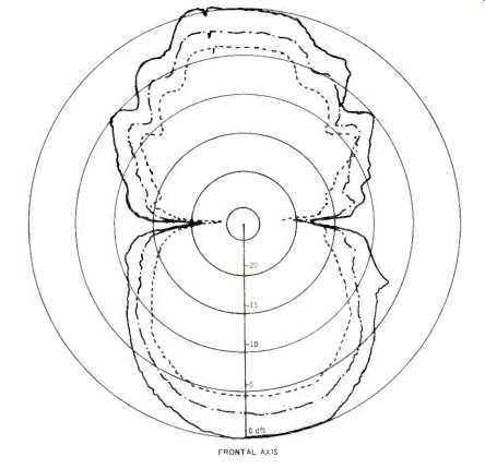
Fig. 7-Polar energy response.

Fig. 8-Energy-time plot for a 20 to 20,000-Hz impulsive at one meter from
the speaker.
Listening Test
The first impression one has of the sound of the amt-1 is its unusually clear and extended high frequency response. Because there is as much high frequency energy coming out the rear as out of the front, the sound in a moderately live room may appear bright. Reducing the high frequency response by tone controls may not be the best solution in this case because the direct sound, with the conventional directional effects of the woofer handling sounds below 600 Hz, may then be unbalanced in timbre with the room reverberant field richer in high frequency energy than the direct sound. Positioning the amt-l's in front of a moderate amount of acoustic absorbing material usually gives a good balance of direct-to-reverberant spectral energy.
After no small amount of consternation with stereo image wander, we discovered that one of the amt-1's had been delivered with an out-of-phase Heil driver. It was immediately corrected and the stereo localization improved markedly.
Later, during the technical measurements, this phasing condition was verified. Stereo localization, both side and center, is extremely good with the amt-1.
One side benefit of the broad horizontal dispersion of sound is that a wide stereo image can be achieved in those rooms in which it is impractical to provide wide speaker separation.
This can be effectively achieved by rotating the speakers so as to increase the ratio of early reverberant sound to direct sound.
While well satisfied with the performance of the Heil unit for clarity of response at shattering rock levels as well as soft symphonic passages, it is this reviewer's opinion that the bass unit doesn't fully match the tweeter's performance. Perhaps with a conventional cone tweeter, the balance of low bass and high treble cutoff would give a more conventional sonic balance, but the Heil unit's extended response simply outshines the woofer's low frequency performance. Higher pitched percussive sounds are accurately reproduced and sharply defined in stereo imagery while percussive mid bass, in this reviewer's opinion, is not as accurate when judged by the Heil unit's standard. In fairness, the bass unit has no trace of the boominess sometimes associated with vented box designs, is clean at moderate to loud levels, and did not reveal any vent sound with program material. This opinion is, of course, related to overall performance without consideration of cost or ease of installation. It is also this reviewer's opinion that the amt-1 gives an extremely accurate sound reproduction for the investment of $300. This, coupled with the wide horizontal dispersion of sound, which gives good stereo for almost any room, makes the amt-1 well worth its price.
-Richard C. Heyser
(adapted from Audio magazine, Dec. 1973)
Also see:
ESS Mk VII Speaker System (Equip. Profile, Jan. 1973)
= = = =