by Stephen Kurtin [Lane Research, Sherman Oaks, Cal.]
Frequency modulation distortion [FMD] is a fundamental consequence of the motion of a diaphragm which is radiating sound at more than one frequency. This form of distortion, which is present to greater or lesser degree in all loudspeaker-produced sound, is believed to be a significant cause of the "listener fatigue" which typically results from extended listening to high-fidelity systems. Consequently, if a loudspeaker system is to produce clean, detailed, well-defined sound, FMD must be controlled.
Although human psychoacoustic sensitivity to FMD has yet to be thoroughly measured, guidelines adequate for loudspeaker design have been experimentally estimated. A simple and commensurate quantitative index of FMD is pro posed as a useful criterion in the design of high-fidelity loudspeaker systems.
Introduction
Frequency modulation distortion [1, 2], the generation of frequencies anharmonically related to those present in the original sound, is a fundamental consequence of the motion of any diaphragm which is required to radiate simultaneously at more than one frequency.
To understand intuitively the physical mechanism which gives rise to FMD, consider a loudspeaker diaphragm simultaneously radiating a high frequency, fh, and a low frequency, f1. The diaphragm is periodically moving toward, or away from, the listener with a velocity corresponding to fi while simultaneously vibrating as required to radiate fh.
Clearly, the higher frequency will experience a periodic frequency shift or modulation, at a rate corresponding to the lower one. FMD is, therefore, simply the consequence of a periodic Doppler shift; hence, this form of distortion is sometimes referred to as Doppler distortion.
Frequency modulation distortion arises directly from the physical process underlying the production of sound. Unlike most other forms of distortion, nonlinearities are not involved; no degree of technological refinement, other than careful design to limit diaphragm excursion, can control FMD. It follows that if modulation distortion is small, other distortions (which, in contrast with FMD, arise from nonlinearities in the loudspeaker mechanism) will usually be negligible. In this article we will assume, therefore, that amplitude modulation distortion is insignificant; modulation distortion will thus refer specifically to FMD.
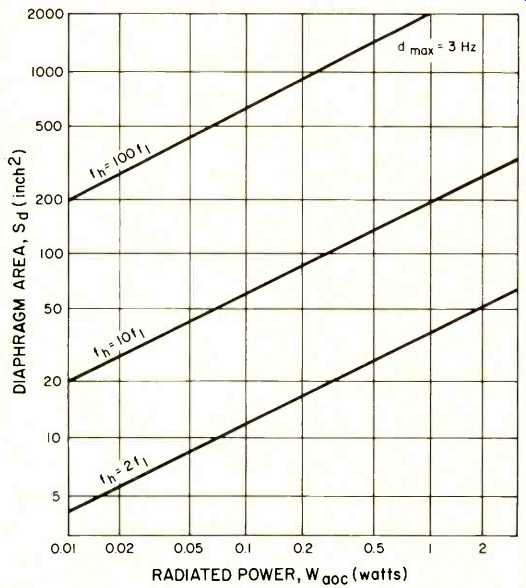
Fig. 1--Equation 7 (see text) relates four significant loudspeaker system
design parameters, diaphragm area, fractional bandpass, radiated acoustic power,
and peak frequency deviation. Qualitative observations suggest that modulation
distortion is inaudible if peak frequency deviation is maintained below 3 Hz.
The figure graphically defines the quantitative relationship between diaphragm
area (considered as a dependent design variable) and radiated power (considered
as an independent design specification) given that peak frequency deviation
is to be maintained at less than 3 Hz. The curves are parameterized by the
remaining independent variable, fractional bandpass.
Note that the inherent frequency response of a loudspeaker system, the one specification which is most often published, is essentially irrelevant to our consideration.
First aberrations in frequency response are not distortions; no spurious frequencies are generated. Second, if a loudspeaker is properly designed to maintain modulation distortion below a target level at rated acoustic power output, whatever amplitude equalization may be necessary to obtain flat frequency response can be inserted without increasing modulation distortion beyond the design target.
As will be quantified later, modulation distortion increases rapidly with both acoustic power level and fractional spectral bandwidth. Loudspeaker systems therefore emit sound which is contaminated with modulation distortion to an extent which corresponds, at each point in time, to the dynamics of the music being reproduced. As a consequence of the transient nature of modulation distortion, and limited research on its audibility, some authorities have claimed that this form of distortion is of little consequence [3, 4], while others pro claim it to be of great importance [2]. The true significance of modulation distortion is perhaps best appreciated by comparative listening to loudspeaker systems which generate differing amounts of it. Notwithstanding plausible arguments to the contrary, the research presented in this paper clearly indicates that the amount of modulation distortion typically present in high-fidelity loudspeaker systems is a real, significant, and easily audible deficiency. It follows that a quantitative index describing the amount of FMD to be expected from a loudspeaker system is an important design criterion for loudspeaker systems.
Analysis
Consider a loudspeaker diaphragm driven to peak amplitude xpk by a sinusoidal excitation at frequency f1. The displacement, x, of the diaphragm may be written simply as:
x =xpk sin 2 pi f_l t (1)
and hence the instantaneous diaphragm velocity is given by
v=x=2 pi f_l x_pk cos 2 pi f_I t (2)
The fractional frequency shift of a higher frequency, fh, being radiated simultaneously by the same loudspeaker diaphragm is proportional to the ratio of the diaphragm velocity at f1 to the velocity of sound, c:
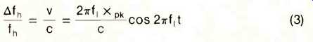 (3)
(3)
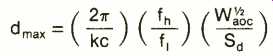
which implies that the peak absolute frequency deviation, d_max, is given by
d_max =2 pi fl fh X pk/C (4)
That is, fh will experience a peak instantaneous deviation of d_max.
Actually, of course, the deviation is periodic and results in energy being scattered out of the input sinusoid at fh into sidebands lying at fh ±nf1 where n is an integer defined to be the "order" of the sideband. It is possible, therefore, to utilize the mathematical tools routinely applied to the analysis of frequency modulation to derive estimates of the total energy scattered into sidebands, or of the amplitude of each side-band. But such analysis is not necessary for understanding the underlying physical mechanism, nor is it required to obtain a useful index of modulation distortion. Indeed, we pro pose here that the intuitively obvious quantity dmax be considered an appropriate index of modulation distortion. This choice is motivated by the results of the psychoacoustic experiments described below.
Although it is useful to have dmax expressed as a function of xpk, cone displacement is not, in and of itself, an acoustically important variable. We will find it generally more valuable to re-express dmax as a function of acoustic power output, W_aoc.
Intuitively, it is clear that there should be a direct relation ship between x_pk and W_aoc. (a loudspeaker is simply a device for moving air; the volume its diaphragm sweeps out per unit time must be the factor which determines power output). In more formal terms, power is simply the product of force times velocity. The relevant force is the radiation resistance term in the equation of motion, namely Rz. For direct radiators over their piston range (ka <.5; where k is 2 pi divided by the acoustic wavelength X, and a is the radius of the cone), R is proportional to f2Sd [5]. We may, therefore, relate the acoustic power output of a loudspeaker to its fundamental operating parameters [5, 6, 7]:
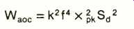 (5)
(5)
where f is the frequency being radiated at a power level of Waoc (watts) as a result of a diaphragm of area Sd (square inches) undergoing sinusoidal motion with a peak excursion of x_Pk (inches), and K is 7.63 x 10^-6.
Equation 5 applies explicitly to a direct radiator mounted in a closed box. Were an infinite baffle to be considered, the power output would be a factor of two larger as a consequence of doubling the radiation resistance (energy is radiated from both sides of a speaker mounted in a true in finite baffle). Horn enclosures provide a tapered impedance match between the driver diaphragm and its air load, thereby greatly enhancing the acoustic power which is radiated for a given peak displacement. For horns, therefore, a multiplicative (and, in general, frequency dependent) constant [5] should be included on the right side of equation 5.
Of course, if xPk is known or can be measured, we can calculate d_max directly from equation 4. The value of equation 5 (or a related equation appropriate to the type of enclosure being considered) is that it allows the speaker designer to calculate basic geometric loudspeaker parameters from an estimate of the required acoustic power and a target maximum allowable modulation distortion index. Solving equation 4 for XPk, substituting that expression in equation 5, and solving the resultant equation for dmaz we find:
(6)
From equation 6 it is clear that modulation distortion a) in root increasing put, b) increases linearly with increasing fractional bandwidth fh/f1, that a given radiator is called upon to handle, and c) decreases linearly with increasing area of the radiator. The significance of these simple dependencies will be highlighted below.
For future reference we will rewrite equation 6 with all linear dimensions in inches, power in watts, diaphragm area as the independent quantity, and explicitly for a direct radiator mounted in a box:
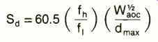 (7)
(7)
Psychoacoustic Considerations
Relatively little definitive study of the human perceptibility of modulation distortion appears in the literature. An interesting audio analog by Klipsch [8] indicates that at modulation rates up to 40 Hz, deviations of as little as 10 Hz peak at 1000 Hz are detectable, and that increasing deviation is distinctly unpleasant. A brief study by Childs [9] indicates the audibility of very low levels of Doppler distortion when pure tones are used as the reference material. In a recent study, Fryer [10] concludes that a few percent FMD is easily detected by both men and women when listening to a wide range of musical material, and that a few tenths of one percent can be detected when pure tones, as opposed to music, are the reference material.
In addition to this modest collection of objective measurements, there is a vast collection of subjective commentary which categorizes horn loudspeakers and large electrostatic panels as being "clean and detailed." Conversely, sound reproduced by many three-way acoustic suspension loudspeaker systems, virtually all of which produce extended frequency response, often lacks detail and is said to be "muddy" or "fatiguing to listen to for extended periods." To obtain design guidelines firsthand, the author and his associates developed a modulation distortion simulator, the output of which was observed, via high quality headphones, by a panel of four males from 25 to 35 years of age. Results were quite uniform and generally in agreement with the earlier observations of Klipsch, both objectively and subjectively.
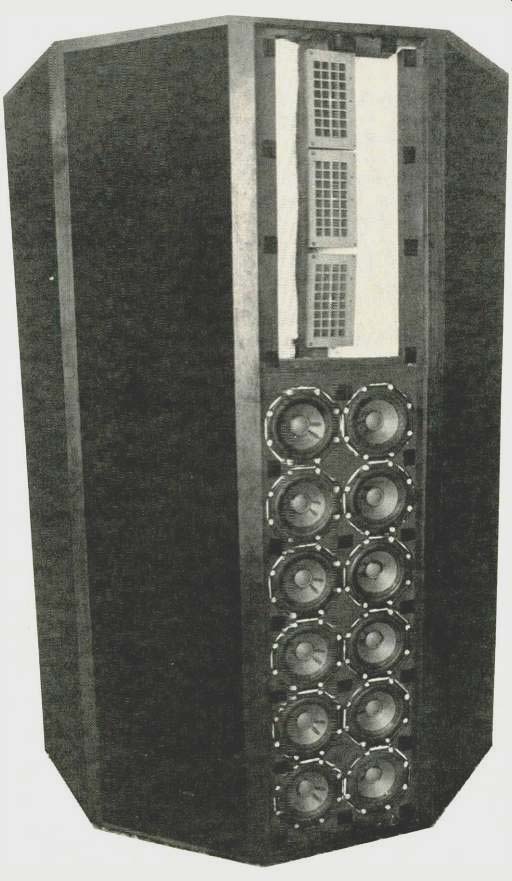
Fig. 2--Photograph of one loudspeaker of an experimental stereo pair designed
for inaudible modulation distortion. The enclosure is in the shape of a regular,
right, decagonal cylinder. The foam grill has been removed from one of the
five identical radiating surfaces to show the three electrostatic elements
and twelve dynamic drivers located on each of these surfaces.
The modulation distortion simulator used for these observations was simply a voltage-controlled integrated circuit function generator, driven by an adjustable reference-quality oscillator. The output of this simulator is inherently free of amplitude modulation, although it may have up to a couple of percent total harmonic distortion as a consequence of the less-than-perfect wave shaping circuitry employed in present-generation integrated circuits of this type.
After several listening sessions, the conclusion was reached that for carrier frequencies between 100 and 4000 Hz, being deviated at rate of 10 to 200 Hz, the critical factor affecting audibility of modulation distortion is the magnitude of the peak deviation. For loud but comfortable listening levels, deviations less than 4 Hz were inaudible; deviations between 4 and 8 Hz were routinely detected; and deviations above 8 Hz were most annoying.
It seems reasonable to surmise that the highest quality high-fidelity loudspeaker systems should be designed to assure that dmax <3Hz, if they are to be free from audible degradation caused by modulation distortion. Using this criterion, equation 7 is plotted as Fig. 1 for several interesting ratios of fh/fi.
Alternatively, one could argue that dmax <3Hz is too stringent a criterion. Perhaps two to five times more modulation distortion could be present without being audible because high-fidelity loudspeakers are used primarily to listen to music, and the ear is apparently less sensitive to FMD in music than in pure tones. The potential deficiencies in this argument are that a) many types of music involve passages in which essentially pure tones are present, and b) human sensitivity to FMD has not yet been thoroughly studied. That is, dmax>3Hz represents some risk of audible FMD; for dmax <10Hz this risk probably is not large.
Sample Calculations
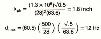
The most popular "high-quality" loudspeaker systems are three-way, bookshelf acoustic suspension enclosures typically having a 10-in. woofer, a 5-in. midrange driver, and a 1-in. tweeter. We calculate below the peak cone excursion (using equation 5) and the maximum harmonic distortion index (using equation 7) to be expected from such systems. The calculation, with respect to each driver, states explicitly the assumed crossover frequencies and the peak acoustic power to be radiated at the low-frequency extreme of that driver's bandpass at maximum listening levels:
Woofer:
Frequency range (to 3 dB points): 28Hz-500Hz
Peak radiated power: 0.5 watt
Cone area: 63.6 inch^2
Midrange:
Frequency range (to 3 dB points): 500Hz-5000Hz
Peak radiated power: 0.5 watt
Cone area: 16 inch^2
Xpk (500)216 = 0.023 inch (1.3x 10⁵)5
dmax = (60.5) 5000 500 ) ( 65) = 26 Hz
Tweeter:
Frequency range (to 3 dB points): 5000Hz-20,000Hz
Peak radiated power: 0.1 watt
Cone area: 0.5 inch^2
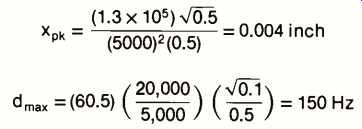
It is now clear that the listener fatigue, which is so common with bookshelf speakers, is a fundamental consequence of their design, and particularly of the relatively small total diaphragm area utilized. Conversely, the reason that large electrostatic panels, despite their other deficiencies, are uniformly praised as clean, open, and transparent is also evident. The control of modulation distortion requires either very low acoustic output levels, restricted bandwidth per driver, or a substantial radiating area. Given the fact that the required acoustic power is set by the room in which the speakers are resident and the loudness preference of the listener, the choice boils down to either a multiplicity of narrow bandwidth drivers or the utilization of large radiators.
Alternatively, horn loading may be employed for the drivers in one or more frequency ranges, thereby increasing the efficiency of that driver and correspondingly diminishing the diaphragm excursion required of the associated driver [2].
Discussion
Utilizing dmax as a criterion, the designer of a direct-radiator loudspeaker system is faced with an interesting problem. Let's review the alternatives starting with the tweeter.
Electrodynamic tweeters typically feature very small diaphragm area, to minimize diaphragm mass and to achieve adequate dispersion. A multiple tweeter array is feasible, if expensive, and such an array could cover the entire tweeter bandpass or each tweeter could, if adequate crossovers can be provided at acceptable cost, cover a successive narrow slice of the bandpass. One practical alternative is an electrostatic tweeter array. Once a decision to utilize electrostatic elements is made, a fixed cost for a power supply and input transformer must be incurred; the incremental cost of additional elements is relatively small. (Electrostatic loudspeakers are limited by their construction to extremely small diaphragm excursion; consequently, there is physically no way for an electrostatic element to produce appreciable modulation distortion. Obviously, therefore, the acoustic output power of one such driver is correspondingly limited and additional elements must be added to achieve the desired acoustic output.) Midrange design considerations are not unlike those mentioned above for tweeters. The area of typical electrodynamic midrange drivers is sufficiently large that, given typical midrange bandwidths and power requirements, a multiple dynamic driver approach is feasible, although electrostatic panels may be preferred for the midrange use as well.
Woofer design is rather different. No reasonably-sized electrostatic can produce significant acoustic power below 50Hz.
The woofer of a wide-range system must, therefore, be a dynamic direct radiator or a horn. Horns with fundamental cutoff frequency below 40Hz are necessarily huge, causing the designer who desires flat response to below 30Hz to select direct-radiator dynamic drivers.
Simply restated, the designer of a loudspeaker system who takes care to minimize modulation distortion must provide very appreciable radiating area at all frequencies. So pro- viding obviously involves costs dramatically beyond those which must be incurred to fabricate a simple three-way bookshelf loudspeaker.
An Experimental System
To test the design criterion proposed herein, the author constructed a two-way stereo loudspeaker system designed to the following specifications:
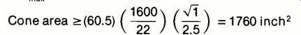
Woofer:
Frequency range (to 3 dB points): 22Hz-1600Hz
Peak radiated power: 1 watt
dmax: 2.5 Hz
Tweeter:
Frequency range (to 3 dB points): 1600Hz-20,000Hz
Peak radiated power: 0.6 watt
dmax: 2.5 Hz

Obviously, a single woofer of the enormous diameter required to provide 1760 in^2 of diaphragm is not suitable for radiating to 2000 Hz. Indeed, it is well known that acoustic radiation from a dynamic driver becomes rather rough and irregular (as a consequence of circumferential "bell" modes within the cone) for all frequencies greater than fc=Cc/2 pi a, where Cc, is the speed of sound in the cone and a is the radius of the cone. (Note that fc is simply that frequency at which the radiated wavelength just "fits around" the outer circumference of the cone.) Taking Cc to be approximately 2100 ft./sec., and desiring fc > 1600 Hz, we conclude 2a <Cc/ pi fc =(2100) (12)/1600 pi = 5 inches. Therefore, drivers of nominally 5 in. diameter, the effective cone diameter of which is typically 4.5 in., are appropriate. The area of each such driver is approximately 16 inch^2; to meet the design criterion, therefore, at least 110 drivers will be required. For such a woofer array, peak diaphragm displacement is less than 0.15 inch to radiate a 22 Hz signal at one acoustic watt.
The tweeter array is composed of 30 electrostatic elements, each having 10 inch^2 of radiating area. Note that (per equation 5) the peak diaphragm displacement required to radiate 0.6 watt at 1600 Hz is only 1.3 x 10^-4 inch! No wonder modulation distortion is controlled.
It is clear that the two-way approach taken stretches woofer response to near its upper limits (the "woofer" is actually an array of midrange drivers), and tweeter response to near the fundamental resonance, at 800 Hz, of the electrostatic elements. An abrupt crossover is, therefore, required. Consequently, an active 1600 Hz crossover with a theoretically optimum [11] third-order Butterworth characteristic was chosen. The low level crossover circuitry includes equalization to compensate for the 12-dB-per-octave roll-off expected, and experienced, below woofer system resonance which, in the experimental sealed enclosure, occurred at approximately 70 Hz. Note that although this approach requires large woofer amplifiers, modulation distortion is caused by diaphragm excursion and the fact that one must push harder, by virtue of the inherent limitations of each small woofer, to achieve the desired excursion is quite irrelevant.
Each column of the experimental stereo pair is in the shape of one-half of a right, regular, decagonal cylinder and contains sixty 5-in. dynamic woofers and fifteen electrostatic tweeters.
The woofer sub-enclosure has an internal volume of 8.5 cubic feet; it is filled with dacron fluff to assure, insofar as is practicable, isothermal compressions. Each vertical exterior surface of the enclosure bears a 2x6 woofer array and three tweeter elements. In this manner, nearly ideal dispersion in the horizontal plane is assured. A photograph of one such columnar exclosure, with the foam grill removed from one of the five identical exterior panels, appears as Fig. 2.
Extensive listening tests confirm that, in accordance with its design goals, this speaker produces clean, well-defined sound that is notably free of audible modulation distortion.
And, as result of elaborate equalization which is built into the active crossover, the free field frequency response is exceptionally flat from 22Hz to 20,000Hz.
The apparent physical extravagance of this two-way design leads one to reconsider three- or four-way designs. Unfortunately, all that is gained by going to larger woofer drivers and a three- or four-way design is the use of fewer low frequency drivers and a somewhat moderated power requirements with respect to the woofer amplifier. In exchange, the crossover becomes more complex, multiple midrange drivers must be utilized, and additional equalization may be required.
Summary
An easily calculated index of modulation distortion, dmax, has been proposed for use as a criterion in the design of high fidelity loudspeaker systems. This criterion has been shown to be fundamentally related to the physics of sound reproduction and intuitively valid. Experimental observations, while not yet definitive, indicate that a well defined upper bound for dmax of approximately 3 or 4 Hz will assure freedom from audible modulation distortion. An experimental loudspeaker system constructed in accord with the criterion developed herein subjectively confirms its validity. At present, technological and practical considerations dictate that loudspeaker designed for low modulation distortion are large and expensive.
Acknowledgement
The author would like to thank R. Small for his extremely helpful advice during the course of this research. The author is also indebted to N. Puckett and E. Kelm for their assistance in the design and testing of much of the electronic apparatus used in this study, including notably the modulating distortion simulator, and various active filters and equalizers.
References
1. G. L. Beers and H. Belar, "Frequency Modulation Distortion in Loudspeakers," Proc IRE 31,132 (Apr., 1943).
2. Paul W. Klipsch, "Modulation Distortion in Loudspeakers." IAES 17, 194 (Apr., 1969); "Part II," JAES 18, 29 (Feb., 1970); " Part Ill," IAES 20, 827 (Dec., 1972).
3. E. J. Jordan, "The Design and Use of Moving Coil Loudspeaker Units," Wireless World (Nov., 1970).
4. Roy F. Allison, "Doppler Distortion Again," Audio, March, 1971, p. 54.
5. H. F. Olson, Elements of Acoustical Engineering (Van Nostrand, 1940) or, Leo L. Beranek Acoustics (McGraw Hill, 1954).
6. A. N. Thiele, "Loudspeakers in Vented Boxes: Part I," IAES 19, 382 (May, 1971); "Part II," 471 (June, 1971); see egn#81, p. 472.
7. Richard H. Small, "Direct-Radiator Loudspeaker System Analysis," IAES 20, 383 (June, 1972). See also: "Closed-Box Loudspeaker Systems" "Part I: Analysis" IAES 20, 798 (Dec., 1972); "Part II; Synthesis" IAES 21,11 (Jan/Feb, 1973).
8. Paul W. Klipsch, "Subjective Effects of Frequency Modulation Distortion," JAES 6,143 (April, 1958). See also the papers identified in reference #2, above.
9. Roy V. Childs, "Doppler Distortion in Loudspeakers," Audio, Aug., 1970, p. 26.
10. P. A. Fryer "Intermodulation Distortion Listening Tests," presented to the Audio Engineering Society Convention, unpublished.
11. J. Robert Ashley and Lawrence M. Henne, "Operational Amplifier Implementation of Ideal Electronic Crossover Networks," IAES 19, 7 (Jan., 1971).
See also: R. Orban "Comment of Crossover Design" Audio, Jan., 1975, p. 8, and J. Robert Ashley and Allan L. Kaminsky, "Active and Passive Filters as Loudspeaker Crossover Networks," IAES 19, 494 (June, 1971).
(adapted from Audio magazine, Dec. 1977)
Also see:
Time and Frequency Measurements in Loudspeakers [by Richard C. Heyser; July 1977]
= = = =