MANUFACTURER'S SPECIFICATIONS
Rated Output: Main, 2.5 V; Tape, 250 mV.
Output Impedance: 220 ohms designed to operate into 5,000 ohms or greater.
Frequency Response: 20 Hz to 20,000 Hz, +0, -0.5 dB; with equalizer out, 10 Hz to 100,000 Hz, +0, -1.0 dB.
Harmonic Distortion: 0.05 percent maximum at rated output level, 20 Hz to 20 kHz.
Hum & Noise: Phono 1 & 2, 80 dB below 10 mV input, unweighted (90 dB IHF weighted); AUX, Tuner, Tape 1, 2, and 3, 90 dB unweighted (100 dB IHF weighted).
Input Sensitivity: AUX, Tuner, Tape 1, 2,& 3, 250 mV @ 50 kilohms; Phono 1 & 2, 2.0 mV into 47 kilohms, 65 pF.
Program Equalizer Center Frequencies: 30 Hz, 150 Hz, 500 Hz, 1.5 kHz, and 10 kHz.
Equalizer Range: ±12 dB at each center frequency.
High & Low Cut Filters: 12 dB/octave above 7 kHz and below 50 Hz.
Voltage Gain: All controls flat, Phono to Main outputs, 62 dB; Phono to Tape Out, 42 dB; High Level Inputs to Main Outputs, 20 dB.
Monitor, Headphone & Line Output: 12 W/ch., 8 ohms, 20 Hz to 20 kHz, 0.1 per cent THD, or 5.0 V rms into 600 ohm line.
General Specifications:
Dimensions: Front Panel, 16 in. (40.6 cm) x 57,,6 in. (13.81 cm); Chassis, 15 in. (38.1 cm) x 5 in. (12.7 cm) x 13 in. (33 cm) D.
Knob Clearance Required in Front of Mounting Panel: 1 1/2 in. (3.81 cm).
Weight: 26 lbs. (11.8 kg).
Power Requirements: 120 V, 50/60 Hz, 25 to 85 watts.
Price: $1500.00.
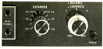
Fig. 1--Close-up view of the expander control.
Devotees of McIntosh equipment have long maintained that if some of the products designed and produced by that respected company endure unusually long life and currency, it is simply because they were "ahead of their time" in the first place. Detractors, on the other hand, accuse McIntosh Laboratory of being "behind the times" and of "not keeping up with the state-of-the-art." Both camps should be totally delighted with Mac's latest component, the Model C-32 Preamplifier. It is a totally new design so flexible in its operating capabilities that a complete description of it would require more pages than are contained in this entire issue of Audio. We have had the unit in our lab for the better part of a month now-and are still finding new applications for it each day. Here, we predict, is a preamp unit that will become a classic in its own time-along with other Mac products that seem to endure while others come and go.
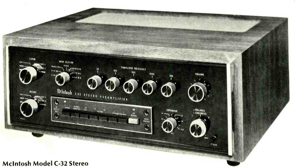
The front panel of the C-32 immediately identifies its maker as McIntosh and consists of their familiar "black glass" face, with gold lettering and gold end-caps. Much of the surrounding gold nomenclature lights up magically in a soft green color when the power On/Off pushbutton (colored red for immediate identification) is depressed. A pair of selector controls at the left are identified as Listen and Record and make it possible to listen to any connected program source while supplying any other (or the same) program source to any of the three tape-out circuits. Since the Listen and Record busses are completely independent, it is also possible to connect a tape recorder to the Listen program line by making a few simple patch cord connections at the rear of the unit. A mode selector switch, adjacent to the Listen selector, has positions for L to L+R, R to L+R, Stereo, Stereo Reverse, Mono (L + R), L + R to L, and L + R to R and affects only program sources selected by the Listen control.
The First Surprise
Five controls along the top of the panel represent a five-band (two octaves per band) built-in equalizer and adjust center frequencies indicated by ±12 dB. To their right is the master volume control while just below are a pair of dual concentric controls which handle channel balance and loudness compensation. The loudness control operates completely independently of the volume control (as a true loudness control should) and can be set to desired Fletcher-Munson "equal loudness" curves regardless of the position of the volume control. This arrangement permits the user to introduce the correct amount of compensation regardless of program source levels, speaker efficiency, or listening room dimensions.
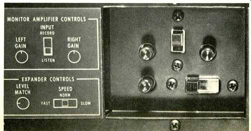
Fig. 2--Close-up of controls and switches on the top surface.
The Second Big Surprise
Coming around clockwise to the last rotary control on the panel, we discovered a knob identified as Expander. Yes, the Mac C-32 has a built-in linear expander which can be set for dB expansion ratios of anywhere from 1.0 (no expansion) to 2.0 (see Fig. 1). More about this expander circuit presently.
Eight pushbuttons (including the red-colored On/Off switch) are framed in an area along the lower section of the panel, along with Tape 3 in and out phone jacks and twin headphone jacks. The latter are not simply paralleled for dual head phone listening. The upper headphone jack is used to feed electrostatic headphones which generally require more power than dynamic types. It is fed directly by (and here comes a third surprise) a 12-watt per channel full-range monitor amplifier built into the C-32. The lower phone jack is intended for feeding low impedance dynamic phones and is fed by the monitor amplifier through an appropriate matching network.
The monitor amplifier can also be used to drive speakers directly and program sources applied to the monitor amp may be selected from either the Listen buss or the Record buss by means of a switch located on the top surface of the preamp (see Fig. 2). Beside the input switch are separate gain controls which adjust the monitor amplifier output level.
Additional controls located in this area determine the level at which the expander makes its transition from "downward" to "upward" expansion and the attack time constant associated with the expansion circuit. Certain types of program material are reproduced more effectively with a slower attack time than others, and three speeds of expansion (slow, normal, and fast) are provided by means of a three-position slide switch.
Since the Listen and Record selectors have only a single Phono setting, the first of the remaining pushbuttons is used to switch from Phono 1 to Phono 2. The next button is a record monitor switch (which tape monitor circuit is monitored depends upon the setting of the Listen or Record selectors). This is followed by an Equalization switch (which either bypasses or introduces the five-band equalizer), low and high-cut filter buttons, and two output selectors which connect the Listen program to either or both pairs of additional output jacks (over and above the main output jacks) and can be used to feed program material to additional power amplifiers feeding remote speaker installations. These buttons also serve to turn remote speakers on and off if an optional remote control SCR relay is connected to an appropriate socket on the rear panel of the C-32.
As for the rear panel, there are a few surprises to be found here 'as well. There are, for example, those familiar spring-loaded speaker terminals at the lower right which are used for connecting a pair of speakers directly to this unit. If you think about the Listen and Record buss arrangement for a moment, you will realize that these speakers could serve as the "rear channels" in a quadraphonic system, or even to provide "ambience" channels when using an audio time-delay unit, since the feed to such a time-delay unit could come from one of the Tape Out circuits and the return could be fed to the alternate buss and extracted via the monitor amplifier. In that way, a second stereo power amp would not be required for these arrangements.
All of the program source input jacks, the three sets of tape-out jacks and the main and extra sets of output jacks are neatly arranged along the top of the rear panel while below are four sets of switched a.c. receptacles plus an additional pair identified as Turntable Power and colored green.
Associated with these latter receptacles is a slide switch which, when placed in the Auto position, permits your entire system to be turned off and on whenever your turntable is activated. A sensing system associated with these receptacles detects the fact that current is being drawn by the turntable and turns on the C-32 (as well as anything else connected to its other switched receptacles) so long as the front panel power switch is left in the Off position. A separate fuse protects these receptacles (which can supply no more than 100 watts) while a main line fuse is located near the power cord at the lower left of the rear panel. A ground terminal, located near the phono inputs and the speaker control relay socket at the lower right completes the rear panel layout.
Internal Construction and Circuit Highlights
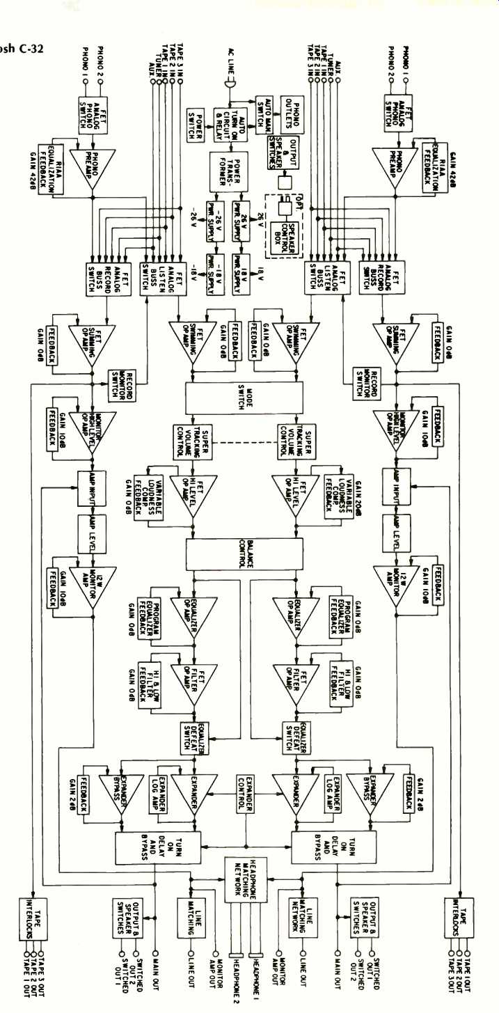
Fig. 3--Block diag.
The views of the underside and top side of the C-32 chassis clearly disclose the flawless workmanship and layout for which McIntosh products have become famous. Flat-ribbon multiple conductor cables can be seen used as interconnecting cables between the various p.c. board assemblies, while all conventional point-to-point wiring is carefully harnessed and methodically routed. A block diagram of the C-32 circuitry is reproduced in Fig. 3. Each phono preamp circuit uses four low-noise transistors arranged in a low-impedance con figuration. To achieve low noise, a 68-ohm feedback termination is used. All program source input switching is done electronically, using FET analog switches. The mechanical Listen and Record front panel switches are single-deck units that simply switch low d.c. voltages which turn the FET analog switches on or off. The master volume control is a step attenuator, and since the switch commutator touches only con tact pads, rather than the actual resistance elements, tracking accuracy (spec'd at within 1 dB over its entire range) is not degraded with continued use. Loudness, equalizer, and band pass filters are all constructed using ion-implanted, junction field-effect op-amps. The logarithmic expander is capable of being switched only into the Listen program line. Signals from the equalizer circuit are applied to a voltage controlled amplifier which operates as a variable gain block, and control voltages for this VCA are developed from a sample taken from the output of the equalizer. Electronic processing of this sample includes band shaping, logarithmic amplification, full wave rectification, level setting, expansion ratio regulation, attack timing, level setting, and d.c. amplification. The resulting voltage controls the gain of the VCA to cause logarithmic gain reduction below set level and logarithmic expansion above that level. A switched bypass link provides a program path around the expander, maintaining a constant signal level regardless of whether the expander is in or out of the circuit.
To minimize hum pickup, the C-32 power transformer is triple shielded (copper strap, silicon steel strap, and steel outer shell). Transformer output voltage is fed to a full wave bridge with 5000 mF filter capacitors to provide ±24 volts d.c. for powering the monitor amplifier. The ±18 volts needed for low level and op amp stages is derived from the 24 volt sup ply and controlled with integrated circuit voltage regulators.
A relay, time controlled by a transistor switch, connects the output of the preamplifier to the output jacks. Transistor switch control is derived from a long time constant, capacitor-charging network which turns on the relay approximately two seconds after the unit is turned on. The same circuit has a short turn-off time constant, which turns off the relay before the preamplifier's main power supply has had a chance to discharge.
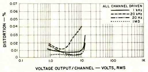
Fig. 4--Harmonic and intermodulation distortion characteristics for the
main output.
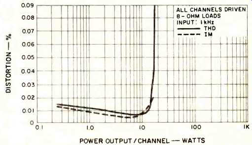
Fig. 5--Harmonic and intermodulation distortion characteristics for the
line/monitor output.
Measurements
Phono equalization was accurate to within 0.2 dB from 30 Hz to 20,000 Hz. Below 15 Hz, a sub-sonic filter rolls off all program sources and is independent of the RIAA equalization. This additional roll-off, though not part of the phono circuitry, tends to reduce response at sub-sonic frequencies somewhat in the manner required by the newly adopted revised RIAA response curve which calls for a roll-off beginning at around 30 Hz. We measured an input sensitivity for phono, for 2.5 volts rated output from the main outputs, of 2.3 mV, and phono overload (at 1 kHz) occurred with a 100 mV input signal-adequate for just about any cartridge tracking any disc we know of. Harmonic distortion in phono (measured at the output) was well below 0.02 percent for any frequency from 20 Hz to 10 kHz, rising slightly to 0.03 per cent at 20 kHz. Signal-to-hum and noise in phono measured 78 dB referred to actual input sensitivity (nearly 91 dB referred to 10 mV as compared with McIntosh's limit spec of 80 dB) and 82 dB when using an "A" weighting network but still referred to actual 2.3 mV input. Translated to a 10 mV reference, the weighted SIN becomes nearly 95 dB as opposed to the 90 dB limit specified by the manufacturer. No matter what reference level you choose to use, these are excellent SIN figures for any phono preamp.
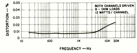
Fig. 6--Distortion vs. frequency for the line/monitor output.
Frequency response using the high level inputs was within 0.25 dB from 20 Hz to 20 kHz and within 1 dB from 10 Hz to 100 kHz. Figure 4 is a plot of output voltage versus harmonic and IM distortion, measured at the Main output terminals.
Maximum output before clipping measured between 10 and 12 volts depending upon the frequency used and, at rated output (with equalization and expander circuits bypassed), THD measured 0.007 percent at 1 kHz, 0.01 per cent at 20 Hz and 0.012 per cent at 20 kHz. IM distortion measured a very low 0.003 per cent at any output voltage (equivalent) level up to 10 volts.
Measurements were repeated using the speaker output terminals to include the monitor power amplifier in the signal path. At 12 watts output per channel (both channels driven, 8 ohm loads), with a 1-kHz test signal, THD measured 0.0075 per cent, while IM distortion was 0.01 per cent. These results, as well as those obtained at lower and higher power output levels, are plotted in Fig. 5. Rated (limit) distortion of 0.1 per cent was reached when the amplifier delivered 16 watts per channel under the same driving and test signal conditions.
Introducing the expander into the circuit tended to in crease THD slightly, but even then harmonic distortion remained well below McIntosh's published limit, with typical readings of 0.018 per cent at the 12-watt output level from the monitor amplifier. Figure 6 is a plot of harmonic distortion versus frequency at the 12-watt-per-channel output level, as measured at the speaker terminals of the C-32 with 8 ohm resistive loads connected. Distortion remained below 0.01 per cent up to around 5 kHz, increasing gradually to a maximum of 0.023 per cent at 20 kHz. In terms of FTC power disclosure requirements, the power amplifier section of this unit might well have carried a power rating of 14 watts per channel, while power band might have been specified as extending all the way from below 10 Hz to 55 kHz for the existing power rating of 12 watts and the rated THD level of 0.1 per cent! If anyone ever doubted the conservatism of McIntosh specifications (or, as they prefer to call them, "performance limits"), these reported readings and measurements should certainly dispel those doubts.
Turning our attention to some of the front panel control features, we next examined the way in which the equalizer controls performed. The sequential stored 'scope sweeps of Fig. 7 were made by running 10 separate traces or sweeps, from 20 Hz to 20 kHz, each sweep made with either maximum attenuation or maximum boost of a single one of the five available band controls of the equalizer section. Center frequencies of each control corresponded very closely with specified frequencies and maximum boost or cut in each case was almost precisely the 12 dB specified. Needless to say, with overall response adjustment capability such as this, there is no need for conventional bass, treble, or even mid range tone controls on this unit.
The response of the high- and low-cut filters was plotted using our spectrum analyzer/storage scope combination, and it is interesting to note that the action of the permanent sub sonic filter is clearly discernible even in the "flat response" position with the low-cut filter out of the circuit. To illustrate this action, the 20-Hz low limit of our sweep was deliberately offset slightly, since at 20 Hz the subsonic filter has no effect.
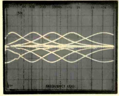
Fig. 7-Control range of the five EQ controls.
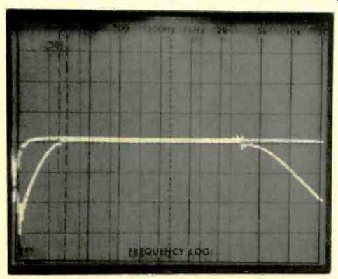
Fig. 8-Response of the low- and high-cut filters.
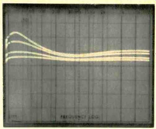
Fig. 9-Loudness compensation response curves.
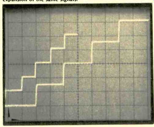
Fig. 10-Left display shows 10 dB steps of increasing amplitude without
expansion. In right hand display, with expander set to 1.5, the downward
and upward expansion of the same signals.
Examples of the loudness compensation curves available through the use of the separate loudness control were plotted for the 'scope photo of Fig. 9. All of these curves were made for an arbitrary setting of the volume control which, as we mentioned earlier, is totally unrelated to the loudness-contour control. While this arrangement permits the user to properly utilize loudness compensation at any listening level, the method of use is somewhat different from that which most audio equipment users are accustomed to and a bit of explanatory material in the owner's manual might prove helpful. As matters stand, the user is left pretty much on his own when it comes to setting up this control.
While the action of a linear expander is probably familiar to most readers and has been verbally explained earlier, we sought nevertheless to present the action of the C-32 ex pander in a more graphic way. After some experimentation (and thanks to the flexibility of our Tektronix 5L4N spectrum analyzer), we devised a technique which resulted in the scope displays shown in Fig. 10. The 51.4N analyzer can be set so that it is responsive only to a single frequency (in this case, 1 kHz), even though the horizontal sweep on the scope display moves across the screen. Having tuned the analyzer to 1 kHz, we fed a signal of that frequency into one of the high level in puts of the C-32 and applied the output to the vertical input of the analyzer. A very slow sweep was initiated, and after each horizontal division was traversed, we increased the signal input level by 10 dB for a total of 40 dB of amplitude change. The "steps" formed by the leftmost trace show this 10 dB progression, since during this first pass the expander control was in the off position and the preamplifier operated in a perfectly linear fashion. Next, we turned on the expander control and set it to 1.5 linear expansion. Starting at the same signal input level as before, we once again began a 'scope sweep, only this time we allowed each level to remain constant for two horizontal divisions, so that the second display would not overlap and confuse the first one. As you can see, each 10 dB of amplitude increase now resulted in a 15 dB in crease as seen at the output of the C-32 (each vertical division on the analyzer's scope face equals 10 dB of amplitude change). Thus, at low signal levels, the output has been "downward" expanded (it is lower in amplitude than it would have been with the expander out of the circuit), while at levels above the "level match" setting (mid-screen, vertically), outputs become progressively greater than those in the earlier display. Note that each successive increase of 10 dB in input level resulted in almost precisely a 15-dB increase in output level. (Thus, 15 dB/10 dB = 1.5, the ratio of expansion selected by means of the front panel control.) Putting it another way, a "program" having only 40 dB of dynamic range has been expanded to 60 dB of audible dynamic range.
The attack time selected for this display was "normal." Had we chosen the Slow attack time available, we would have observed a slight "rounding" of the rising or leading edge of each "step," indicating a slight time lag in the action of the expander. Using the "fast" setting would have resulted in even sharper "corners" for each of the expanded steps than those recorded.
Speaking of attack time of expanders, should you ever have occasion to measure the C-32 you will find that with the expander "in circuit" any attempts to measure IM distortion will be rather meaningless, and readings are likely to be higher than you would expect. Such readings do not actually represent IM distortion (which is normally defined as sum-
and-difference products between the 60 Hz and 7000 Hz tones that make up the IM test signal), but rather the emergence of slightly time-delayed low frequency 60 Hz components which the expander circuit cannot "track" instantaneously. In actual listening tests, these odd results do not show up as audible IM distortion which, as we have said, they are not.
Listening and Use Tests
Even if one ignores all those extra circuits and simply hooks up the McIntosh C-32 as a straight phono preamp/control unit, its superior listening qualities are immediately apparent. Apparently bowing somewhat to the "wideband" school of audio enthusiasts, McIntosh engineers have seen fit not to roll off response above 20 kHz in this unit (though, in previous products they have maintained that response beyond that audible limit contributed nothing to purity or accuracy of sound). Whether because of this ex tended response or because of the obviously excellent overall stage-by-stage design, the sound quality reproduced using this preamplifier is as good as anything we have heard to date-regardless of price. When you consider the fact that one is really dealing with what might well have been four products here (a high-quality preamp/control unit, a five-band equalizer, a linear expander and, yes, a moderately powered high-quality stereo power amplifier), the suggested retail price of $1500.00 doesn't seem high at all. In fact, all things considered it's quite a bargain!
-Leonard Feldman
(adapted from Audio magazine, Dec. 1977 )
Also see:
McIntosh Model C-28 Stereo Preamplifier (Nov. 1976)
McIntosh Model C-27 Stereo Preamplifier (Equip. Profile, Sept. 1978)
McIntosh Model MR-78 FM/Stereo, FM Tuner (Feb. 1977)
= = = =