SYSTEMATIC THINKING

For the last several months we have examined the various theoretical underpinnings of digital audio. Topics such as sampling and quantization and the way their limitations dictate digital design are critically important, but man does not live by conceptualization alone; he also needs hardware. This month I would like to jump into that particular domain with a look at a complete digitization system, focusing on a PCM hardware design.
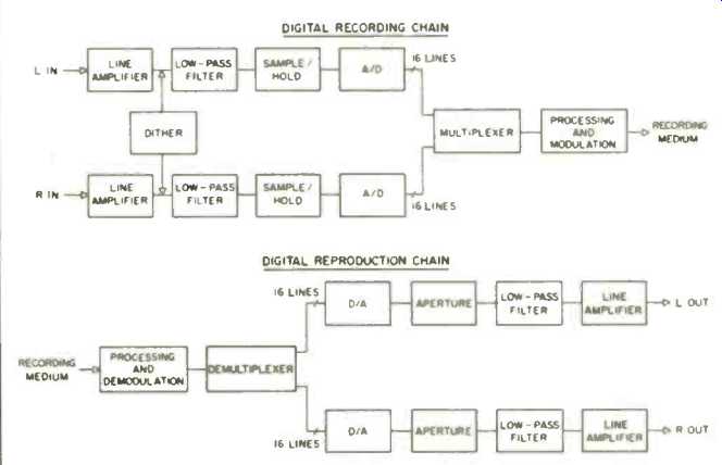
A classic stereo PCM digitization scheme is shown in Fig. 1. The recording section consists of input amplifiers, a dither generator, input low-pass filters, sample-and-hold circuits, analog-to-digital converters, a multiplexer, digital processing and modulation circuits, and, of course, a storage medium such as digital tape. On the output side are demodulation and processing circuits, a demultiplexer, digital-to-analog converters, aperture circuits, out put low-pass filters, and output amplifiers. This hardware collection is thus the realization of our previous conceptual mathematical theorems. As we have discussed, the whole point here is that of digital storage and the tremendous advantages it presents.
Thus, an audio digitization system is really nothing more than a kind of transducer which processes the audio for digital storage, then processes it again for reproduction. While that sounds simple, the hardware must be carefully engineered, for success in accomplishing its task (and the resulting quality of the reproduced audio) depends entirely on the quality of the system's design. Whoever said that all digital audio products sound alike never designed one or tried to manufacture it competitively. . . .
Aside from the requirement of absolute quality, so as to not compromise the fidelity of the ensuing digital system, there is nothing interesting about the input amplifier. The dither genera tor, as discussed last month, is a con trolled noise circuit typically outputting white noise. Our first engineering challenge occurs with the input filter. The analog signal is low-pass filtered by this very sharp cutoff filter to band-limit the signal and its entire harmonic con tent to frequencies below half the sampling frequency. On a professional recorder with a sampling rate of 48 kHz, the filter's cutoff will be set around 22 kHz to allow for maximum attenuation at the half-sampling point. A number of analog filter designs may be employed for this purpose, such as types corresponding to Bessel, Butterworth, or Chebychev polynomials. All of these designs offer a flat pass-band, sharp cutoff, and a low stop band. Thus, our band-limited signal passes to the sample-and-hold circuit.
The input sampler samples discrete values of the input signal at a fixed periodic rate, and it holds each analog value while the analog-to-digital con version takes place. This is required because a varying input to the A/D converter could result in error. A sample-and-hold circuit is essentially a capacitor and a switch. The circuit tracks the signal until the sample commands cause the switch to isolate the capacitor from the signal: the capacitor holds that analog voltage during conversion.
The timing of the sample command must be carefully regulated to prevent jitter, the phenomenon of incorrectly varying sample times. Furthermore, the capacitor must be carefully chosen and isolated to prevent any loss of voltage, known as droop.

Fig. 1--Block diagrams of digital recording chains, and reproduction.
Our signal now appears as a staircase, a hybrid analog signal ready for conversion. The analog-to-digital converter is the most critical and costly component in a digitization system.
Consider: This circuit must transform the analog signal into as many as 65,536 steps, and it must accomplish that task in 10 or 20 µS. Fortunately, several circuits are available for this operation. A successive-approximation converter contains a digital-to-analog converter: it tries a digital word, converts it and compares the analog result to the original input, then corrects its approximation until the proper digital word has been determined and output. Integrated A/D converters offer another design approach, a timing circuit. A capacitor stores the input analog voltage, and then the timer counts as the voltage is discharged. The number of counts in that timing becomes the output digital value. Whichever method is used, we have accomplished our initial goal of digitizing the analog signal.
Now that we are in the digital do main, software becomes king and the fun begins. The output of the A/D converter is raw binary data ready to be processed as the designers see fit.
However, a number of operations must occur. First, the A/D output is parallel data and our storage devices permit only serial data. Thus, the data is multiplexed: that is, parallel data is converted to serial. Secondly, a data code must be structured to identify the original data words in the resulting bit stream. Perhaps the most intriguing operation takes place at this point. In analog recording, an error is an error, and that’s that. In digital we may provide for error detection and correction.
The data stream, therefore, is provided with parity bits and redundancy checks, extra data created from the original data to help detect errors. In addition, data is redundantly written for error correction. Finally, the data is modulated and formatted prior to re cording on tape. This latter step is hotly debated among manufacturers, as formats and standards are always wont to be.
The storage medium itself can be fixed- or rotating-head tape recorders commonly found in the professional studio. Many recording engineers prefer fixed head designs because of ease of editing and historical familiarity: however, rotary-head video recorders are more efficient. But no matter what happens in the studio, the data is eventually transferred to the Compact Disc for consumer playback. Both the CD player and the professional’s recorder follow the reproduction side of our digitization chain.
The reproduction circuits take care of many housekeeping functions, such as demultiplexing. In this process, the data stream is recovered from the modulation scheme and is again put into parallel form. Our foresight in placing error-detection and correction safeguards in the digital signal prior to storage pays off here. Any errors introduced by the tape or disc are detected and corrected or concealed. This includes mechanical errors such as transport wow and flutter: our data is output at a constant speed referenced by a crystal clock.
The digital-to-analog converter's task is the reverse of the analog-to-digital converter's, but simpler. It is inherently easier to accomplish a digital-to-analog conversion because of the nature of the circuit's design.
Many D/A converter types are used, but the most common type is the weighted-resistance D/A. Each of the input bits (usually 16) is converted to a current according to its weighting: for example, the most significant bit would yield a larger current than the second most significant bit, and so on, with each bit value changing twofold. The currents are added and converted to a voltage which corresponds to the original voltage prior to the A/D conversion.
For economy's sake, sometimes one D/A converter is shared between channels.
An aperture circuit essentially consists of a switch which is timed to wait for the D/A conversion. When the D/A output voltage is stable, the switch passes the voltage. This removes unstable values and improves the frequency characteristics of the pulse amplitude signal (PAM) present at this point. It is gated as a function of the original sampling frequency: the aperture circuit acts as an output sample-and-hold circuit to accomplish this.
The output low-pass filter is substantially identical to the input low-pass filter and performs the same cutoff function. The staircase function is smoothed, removing all the high-frequency components of those sharp edges, and the original waveform is recovered. Either an analog filter or an oversampling (digital-filter) technique, as found on some CD players, may be used. With oversampling, the sampling frequency is multiplied, and thus extended, and a more gentle cutoff filter may be employed. Theoretically, less phase shift occurs, but perhaps the best reason for selecting the oversampling technique is that a 14-bit D/A converter may be used instead of a 16-bit. Beware of claims by manufacturers which imply that oversampling doubles or quadruples the sampling rate as well as the audio high-frequency limit.
Nothing of the kind occurs: oversampling is merely a very ingenious method of output filtering. The final part of our digitization system is the analog amplifier, again hopefully designed with care (by analog designers, not digital specialists).
That's about the size of it. A complete digital audio system isn't really all that difficult, at least in block-diagram form. And even in actuality it isn't an impossible situation. When taken block by block, each part may be thoroughly understood in detail. In later columns, we'll be looking into that. You'll be building your own Compact Disc player in no time.
Also see: Philips Oversampling System for Compact Disc Decoding (April 1984)
(adapted from Audio magazine, Dec. 1984; KEN POHLMANN )
= = = =