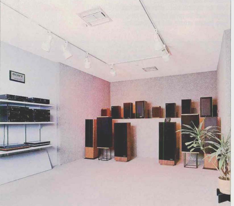
An LEDE demonstration room designed by the author for The Audio
Authority in Reno, Nevada
by William R. Hoffman
[William R. Hoffman is a senior technician at Precision Audio Labs, Reno, Nevada. This article, a limited application of the live-end/dead-end concept, is based on research and development work by Don Davis of Synergetic Audio Concepts, San Juan Capistrano, California. The term LEDE is a trademark of his company. ]
Your listening room has a great effect on the sound of your system because of reflections. Here's how to tame them.
Recent developments in sound recording have begun to put more demands on the entire chain of sound reproduction equipment. With the advent of 14- and 16-bit digital coding systems and the Compact Disc as a viable sound-storage medium, the limits formerly set by the natural shortcomings of the vinyl LP record and magnetic recording tape have disappeared. Without the limits on signal levels set by the noise floors of these media, the ability to record low-level information containing the acoustics and character of a particular environment is unprecedented. But with this impressive recording capability must come a reproducing system that can clearly re-create these sounds, including all the important acoustic cues used by the human brain in determining the quality and nature of the original sounds. Electronics and loudspeakers are now avail able with the required level of performance to meet these needs, yet this is not enough.
The acoustics of the listening room play a major part in the perception ability of the listener. Even the most sophisticated loudspeaker system will be helpless in poor acoustic circum stances. When problems exist, the only remedy is to apply known principles of acoustics-some only recently come to light-to the situation. Then, under correct circumstances, the full capability of digital sound reproduction can be realized.
Room Acoustics and the LEDE Concept
In 1972, Haas [1] showed that the acoustical anomalies of an enclosed space had almost no appreciable effect on the perceived sound from a loudspeaker if one important characteristic of the radiated sound field was carefully preserved: If the direct sound radiated from the loudspeaker was al lowed to reach the listener well before the sounds reflected from adjacent room surfaces, then the brain would almost totally ignore the later sound and accept the direct output as the only one present. Specifically, Haas showed that a delay between the direct and reflected sound of more than about 20 mS, equivalent to a distance of about 23 feet, was sufficient to allow complete differentiation under normal circumstances. In addition, he showed that this delay requirement was modified by the strength of the early-arrival sounds. The concept of direct, early, and late sound arrivals is illustrated in Fig. 1.
Another artifact produced by these early reflections is clearly evident when an analysis is made by the use of Time Delay Spectrometry (TDS). Figure 2 shows the output of a studio monitor loudspeaker, both without (Fig. 2A) and with (Fig. 2B) very early reflections. Note the smooth response of the speaker in free space (anechoic conditions) and the very ragged response when the early reflections are added.
Complete cancellation of some frequencies will occur when the delay is sufficient to make the direct and reflected output 180° out of phase. Clearly, then, if it were possible to eliminate all early reflection effects, not only would the actual response of a speaker be much smoother, but as far as the perceptions of the listener would be concerned, the room would take on the qualities of an echoless, free-space environment.
As Fig. 1 illustrates, the critical surfaces are those near the loudspeaker system, in the end of the room where the speakers are located. Deadening these surfaces will remove the early reflections, but treating the walls with sufficient damping material could both be expensive and require changes in the room structure-and this is not al ways practical.
Yet, another approach is possible: Creating a live-end/dead-end (LEDE) environment, by eliminating the sound radiated by the speakers in the unwanted directions. This can be accomplished by the placement of absorptive materials between the speaker and any nearby surfaces. Specifically, by using a number of free-standing absorptive panels, arranged around the loudspeaker in a semicircle or a horse shoe-shaped array, no wall treatments may be necessary.
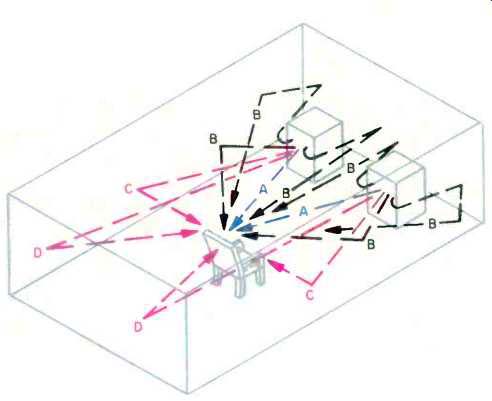
Fig. 1--Lateral reflection patterns in a listening room, showing
some paths of direct sound (A), early reflections (B), and late reflections
(C) and (D).
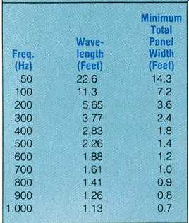
Table 1--Minimum panel array width required to avoid diffraction, for various
sound frequencies and wavelengths (where panel width = 717/f).
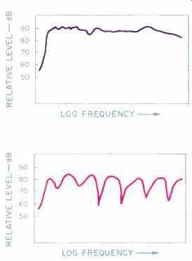
Fig. 2--Frequency response of reference loudspeaker system under anechoic
conditions (A) and with effects of early reflections (about 1.1 mS delay)
added (B). (After Davis.)
Construction of the Acoustic Panels
Figure 3 shows cutaway views of the suggested panel construction. Note that the panel is simply a wooden frame with a solid back, and with architectural fiberglass or rock wool placed inside as an acoustical absorber. Covering the front surface is a thin, open-mesh grid made from screen or chick en wire, stapled to the wooden frame, which retains the absorbing material. A stretched fabric cover is placed over the entire assembly, either fastened by stapling or sewn as one piece and pulled down over the panel, like a sock. Completing the job would be some brackets, or a wood or metal plate, attached to the bottom to sup port the panel upright.
Note that such a construction is very simple and inexpensive and that it al lows the builder to select the style and color of the outside material. In addition, should the cover ever become damaged, it could easily be repaired or replaced. The only important requirements for the panels are their dimensions and absorptivity, which are quite easily determined.
Designing the Panels
In designing the panels it must be realized that they will be acoustically effective when two conditions are met.
First, their vertical, and horizontal dimensions must be great enough so that the sound waves will not go around them due to diffraction. Second, the sound-absorbing material must be effective over the required range of frequencies. For our purposes, this range is from the low-frequency limit deter mined by room dimensions and panel construction to at least 2 kHz, with at least 80% absorption.
Before proceeding any further, we must have some knowledge of the circumstances under which our treatment will be used. To begin with, we must examine the room in which our sound system is located, and especially the area where the loudspeakers will be placed. This LEDE system works best when the speakers are well away from any wall surfaces-a typical arrangement for many listening rooms today.
Keeping in mind that the absorbent panels must eliminate reflections from all surfaces within a radius of approximately 10 to 12 feet, plan enough of them to block all sound radiation to ward these surfaces. The panels should be spaced 1 to 2 feet from each speaker in an open, semicircular pat tern, as has been mentioned.
Now that we have a general plan for the system, we can use the following four-step procedure to determine both the panel dimensions and the thickness and density of the absorbent material to be used.
The first step is to determine the lowest frequency that needs to be absorbed by the panels, which is a function of the dimensions of the listening room (usually the floor-to-ceiling dimension). To determine this frequency, find the smallest room dimension, in feet, along the bottom of the graph of Fig. 4, and then the corresponding low-frequency cutoff limit for that dimension.
Next, proceed to Table I. From the value of low-frequency cutoff, deter mine the required total panel width.
You may extrapolate for values that are between those given; this will cause no problems, as the exact dimensions are not critical. Note that this dimension is to be the minimum overall width of the array of panels that will be built, and is not necessarily the dimension of just one panel only, unless it is convenient to build just one panel.
Next, we must determine the approximate absorption characteristics of the panels according to the material we will place inside them. Table II lists values for standard architectural fiber glass or rock wool. Most of this material is available in 2- or 3-inch thick nesses, and in various densities from about 2 to 6 pounds per cubic foot.
Although it comes in various widths, 2 feet is probably the most common. It can be purchased from most lumber yards or material supply houses. What is to be purchased is the common fiberglass or rock wool, with no backing material.
Looking at Table II, it is obvious that even very light material is quite absorptive, and the thicker and denser it is, the more effective it will be. Choose the best material you can obtain that will meet the 80% minimum requirement over the range from the low-frequency cutoff (from step 1) to at least 2 kHz. (But note, also, that at the low-frequency limit the absorption can drop to about 50% or so without causing any difficulties.) Our final step is to determine the dimensions of the panels we will con struct, as taken from the material thickness, low-frequency cutoff point, and array dimensions we have already determined. To begin with, the frame depth must be equal to the fiberglass thickness plus the thickness of the backing material. The panel width will be determined by the size of the speaker system. This dimension is not critical, provided that the width of the array, as it will be arranged around each loudspeaker, meets or exceeds the minimum value from Table I. In most cases, this will be no problem.
Now the only remaining dimension to determine is the panel height. Again, this is not critical--as long as the panel is taller than the loudspeaker by the value of the minimum panel width (taken from Table I).
==================
HOW SOUND IS ABSORBED
The process of sound-wave absorption is a complex one, actually involving several simultaneous mechanisms. In general, absorption is accomplished by converting the acoustic energy in the air into other forms of energy, such as simple heat or mechanical motion.
Specifically, in a fibrous tangle (such as fiberglass or rock wool), the acoustic waves that enter the material will also proceed to propagate through it. In the process, a portion of their energy will be converted into heat by the frictional and viscous properties of the tangle. In addition, the fibers of the material are set in limited motion, further reducing the energy in the wave. Altogether, the cumulative effects of these mechanisms will vary with two important factors: Density of initial packing, in pounds per cubic foot, and the mass of each of the fibers in the material used.
One other effect of the fibrous tangle is the reduction of the speed of sound (normally about 344 meters/second, or 1,130 feet/ second) for the waves passing through the material. Fig. B1, after the work of Bradbury [2], shows the change, which is a function of the density of the material according to the formula:

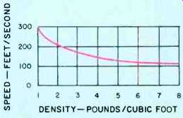
Fig. B1--Speed of sound versus packing density of material. Speed in air
is normally 1,130 feet per second. (After Bradbury.)
==================
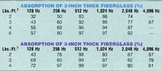
Table II--Percentage absorption vs. frequency for fiberglass panels of various
densities. (After Knudsen, Owens-Corning Fiberglas Corp.)
Design Examples
To help understand the procedures, let us do some sample problems. Say a room is 14 feet wide by 19 feet long, with an 8-foot ceiling. The loudspeakers are about 1 foot wide by 2 feet high by 1 foot deep, and are on stands 1 foot high, making the arrangement 3 feet high overall.
To begin with, Fig. 4 tells us the low-frequency limit we need to deal with is about 420 Hz, taken from the room's minimum dimension, its height of 8 feet. Then, Table I tells us that the minimum array width will be about 1.8 feet, based on the 420-Hz limit. Also, with the limit in mind, and from what is available in fiberglass, we select 2-inch material of 4-pound density, giving us much more than the minimum 50% absorption at the low-frequency limit. This means the panel's depth will be 2 inches plus the thickness of the backing we use.
Now we can determine the panel height. The height of speaker and of the minimum array width, 1.8 feet, and we have 4.8 feet (minimum). Finally, from the dimensions of the speaker cabinets (1 foot wide by 1 foot deep), and allowing approximately 1 foot clearance, we see that three panels, each 3 feet wide, will surround the speaker on three sides. So a total of six panels will be needed.
Here is another example. We have a room 12 feet by 10 feet, with an 8-foot ceiling. The loudspeaker is a three piece system, with two satellites measuring 8 inches square and a single subwoofer. The satellite speakers are on stands that raise them to a height of 3.5 feet overall. For this room and system combination, Fig. 4 tells us the low-frequency limit is again 420 Hz, determined by the ceiling height dimension of 8 feet, and again the mini mum array width is set at 1.8 feet, taken from Table I. Also, given the same low-frequency limit, we can again choose to use 2-inch fiberglass with 4-pound density, since its absorbency will meet the minimum needs of the system.
Now, from the small dimensions of the satellite speakers, it is obvious that three panels of 21-foot width will be sufficient for each speaker. Finally, the panel height will be the speaker height, with stand (3.5 feet), plus the minimum array width of 1.8 feet, to' a total of about 5.5 feet.
It should be noted here that no treatment has been applied to the bass system used. Because the effective low-frequency limit of the absorption panels is about 420 Hz, and the bass module only operates up to about 150 Hz (typical), it is obvious that no treatment is necessary for it.
Let's take one more example, this time involving a large room. 18 feet by 28 feet, with a raised architectural ceiling having an average height of 16 feet. The loudspeakers used in this room are large, multi-driver, extended-range systems, 3 feet wide by 7.5 feet high by 1.2 feet deep.
Now, this example represents an extreme for the free-standing panel's absorption system. To begin with, Fig. 4 tells us we have about a 200-Hz low-frequency panel cutoff for this room, based on the 16-foot dimension. Table I gives a minimum width, for each array of panels, of about 3.6 feet. In addition, with this rather low cutoff frequency, fiberglass of at least 2-inch thickness and 4 to 6-pound density will be required. Indeed, such a system will benefit from even more absorption, to help reduce the multiple return echoes that occur in such a large room, so a 3-inch thickness is recommended.
To complete the design work in this example, it is obvious these large speaker systems will require either a large number of panels or a few panels very wide and tall. In this case, we can allow the builder to choose his design to fit his space and needs. As an ex ample, panels 3 feet wide, two behind each speaker and one on each side (for a total of eight), may be chosen, with a minimum height of about 11 feet (the speaker height of 7.5 feet, plus the array minimum-width dimension of 3.6 feet). Their thickness would be 3 inches, plus backing thickness. Please note here that with panels this heavy and tall, vertical stability may be a problem. Therefore, additional upright supports may be necessary or possibly even suspension from the ceiling.
Final Suggestions
Now that the basic LEDE system de sign has been prepared, a few additional points need to be made for the system to work at its best.
First, the LEDE system we have considered here has been designed to prevent any early reflections on all critical walls within the listening area. But there are other sources of problems.
The first is the floor directly in front of the loudspeakers. In most rooms, the floor is only a foot or so beneath the loudspeaker drivers, and therefore is potentially a source of early reflections.
In many rooms, carpeting covers much or all of the floor, minimizing these reflections. If it does not, then some kind of substitute must be provided. A rug, or similar, will suffice in most cases, provided that it extends at least 5 to 10 feet in front of the speakers.
Another source of reflections is the ceiling, especially if it is low and the loudspeakers are tall, or set on tall stands. Again, in most cases this is not a problem, as contemporary construction usually includes adequate ceiling treatment. In the event this is not the case, then acoustical tile or similar material, should be used.
A second point: With the advent of Time Delay Spectrometry, an interesting phenomenon was noted when testing some rooms for the effect of early reflections. When a loudspeaker was set firmly on an acoustically live surface, such as a wooden floor, the measured output from the loudspeaker also included some "pre-echo" sound that originated from the speaker, yet arrived before the speaker's direct sound through the air. This phenomenon was traced to the wooden floor-vibrations from the bass driver were coupled through the speaker cabinet, then through the floor, and were then re-radiated into the air near the microphone used for the measurements. The wood was conducting the sound faster than the air did, and therefore brought the sound to the pickup microphone first. This some what surprising phenomenon is also a source of early-reflection effects, and it will cause the same response irregularities as shown in Fig. 2B. Therefore, the treatment of the floor with a carpet has a second advantage: Seeing that the loudspeakers are not firmly coupled by their own weight to a transmittive surface that can retransmit sound into the air.
Finally, a word of caution. Attempting to implement the LEDE concept in systems where the loudspeakers are a "Direct Reflecting" type will not be successful. These speakers require the many early reflections, because this is what provides the acoustic effects that the systems were designed to have.
Under such circumstances, a live, unaltered room is absolutely necessary.
For all other system types, even dipole "screen" systems, that do have a degree of backward radiation, the LEDE treatment will still work well. These speaker types do not exclusively depend on their rear radiation for normal operation.
We will conclude this design feature by describing a more complete implementation of the LEDE system, one in which we will actually modify the room surfaces themselves.
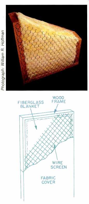
Fig. 3--Photo and cutaway view of absorption panel's construction. The panel
should have a solid backing (not shown).
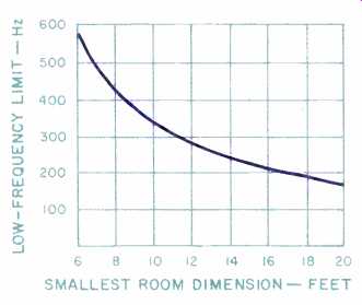
Fig. 4--Lowest effective frequency for acoustic-panel absorbers as a function
of room size (where f = 3,390/smallest room dimension in feet). For frequencies
below those shown, other forms of absorption (such as wave cavities) would
be needed.
References
1. Haas, H., "The Influence of a Single Echo on the Audibility of Speech," Journal of the Audio Engineering Society (JAES), Vol. 20, 1972.
2. Bradbury, J. L. S., "The Use of Fibrous Material in Loudspeaker Enclosures," JAES, Vol. 24, 1976.
(Source: Audio magazine, Dec. 1986)
Also see: Earning a Deaf Ear: Loud Music & Hearing Loss (Jan. 1989)
= = = =