Manufacturer's Specifications
Tuner Section
Mono Usable Sensitivity: 14.3 dBf
Mono 50-dB Quieting Sensitivity: 18.3 dBf.
FM Mono S/N: 78 dB.
FM THD: 0.15%
FM Alternate-Channel Selectivity: 72 dB.
AM Suppression: 62 dB.
FM I.f. Rejection: Greater than 75 dB; nominal, 82 dB.
FM Capture Ratio: 2.5 dB.
FM Stereo Separation: 46 dB.
AM THD: 1.2% at 30% modulation, 2 mV input.
AM Selectivity: 30 dB.
AM Image Rejection: 46 dB.
AM I.f. Rejection: 65 dB.
Preamplifier Section
Frequency Response: Phono, RIAA, ± 1.0 dB; high level, 20 Hz to 20 kHz, ±0.5 dB.
THD: 0.015% or less below 2.0 V output.
S/N: Phono, 80 dB below 5 mV input; high level, 95 dB below 1.0 V output.
Rated Output: 6.0 V.
Input Sensitivity: Phono, 2.7 mV; high level, 180 mV.
Tone Control Range: Bass, ±8 dB at 100 Hz; midrange, ±6 dB at 1 kHz; treble, ±8 dB at 10 kHz.
Muting: -20 dB.
Loudness: 3 dB at 100 Hz.
Headphone Sensitivity: 125 mV for 1 V out at preamp out.
Video Section Frequency Response: 10 Hz to 3.0 MHz, ±2.0 dB.
Input Impedance: 75 ohms.
Video Input and Output: 1.0 V, peak to peak.
General Specifications
Dimensions: 19 in. W x 3 1/2 in. H x 12 1/4 in. D (48.2 cm x 8.9 cm x 31.1 cm).
Weight: 12 lbs. (5.4 kg).
Price: $799.95.
Company Address: P.O. Box 1237, Lynnwood, Wash. 98046.
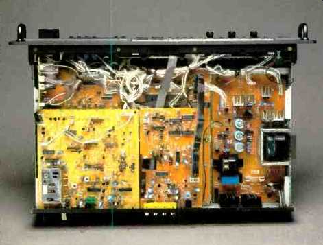

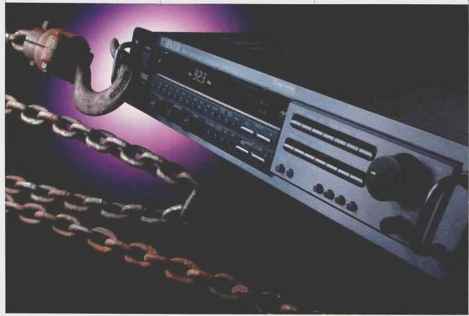
I've often wondered why more manufacturers don't offer tuner/preamplifiers. After all, there are no technical disadvantages to combining a tuner and a control preamplifier in a single chassis, and the arrangement still allows you to choose a power amplifier suited to your needs while reducing the number of basic components in your stereo system from three to two. Obviously, Bob Carver must have felt the same way, but in typical Carver fashion, he has incorporated much more than just a tuner and a preamplifier in this interesting unit. The CT-17 combines the functions of an audio/video preamplifier and an AM/FM tuner, all right, but it also includes a Dolby Pro-Logic surround sound decoder and Carver's well-known Sonic Holography-the circuitry that enlarges the perceived stereo image if you set up your speakers correctly and sit where you are supposed to sit.
For Sonic Holography or normal stereo operation, a two-channel amplifier is all that needs to be connected to the CT-17's main outputs. For the three surround modes (Dolby Pro-Logic, "Hall," and "Simulate"), you would ideally need five channels of amplification-the front and surround pairs, plus front center. However, as there is no difference be tween the right and left surround signals in Dolby Surround, you could use four channels in Dolby Pro-Logic mode if your surround-channel amp can handle the impedance of your two surround speakers in parallel.
The CT-17 has inputs for phono, CD, and AUX; it also has inputs and outputs for two audio tape decks and for an external processor such as an equalizer or a compressor/ expander. In addition, it has audio and video inputs and outputs for a VCR, audio and video inputs for an additional video source, and a video output to feed these sources to a monitor screen.
Besides the attributes noted, the CT-17 is essentially two preamplifiers in one. In other words, you can simultaneously play two different music sources independently in two different areas of your home. Both can be controlled by the CT-17's supplied remote control or by using Carver's room-to-room system, which the company calls RemoteSystemLink.
The owner's manual is well written. It provides adequate descriptions of every feature and, more importantly, has clearly written step-by-step instructions for setting up the various surround sound modes and Sonic Holography. A tour of the controls on the front panel and the remote will clarify how some of the CT-17's features are used.
Control Layout
The power switch, a stereo headphone jack, and an indicator light that reads "ACCD" (when a corresponding pushbutton is pressed) are at the left end of the front panel. "ACCD" stands for Asymmetrical Charge Coupled Detector, a name that Bob Carver gave his special FM stereo circuit ry. Next is a large display area that shows signal strength, tuned-to AM or FM frequency, station preset numbers, type of surround sound in use, volume level for rear or remote channels, and the status of several other functions. Below the display are 10 numbered preset buttons, a "Memory" button for storing presets, a "Preset Scan" button (used for 5-S auditions of each preset station frequency), an "Auto Scan" button (for seeking usable signals on the AM or FM radio band), a "Mono" button, and an up/down tuning bar.
Although there are only 10 preset buttons, each can be used to store two AM or FM frequencies. Holding a button down for several seconds changes the preset from its normal single-digit value (e.g.. 1, 2, 3) to an alternate double digit value (11, 12, 13, etc.).
Below the station presets are rotary bass, midrange, and treble tone controls and buttons for selecting Sonic Holography, ACCD, and AM or FM. An up/down control bar for remote volume is also in this area. Two banks of program source selectors are at the right end of the panel, along with balance and volume controls and buttons for surround mode, tape monitoring, a high-cut filter, and loudness; a "Calibrate" button activates a test signal used in calibrating levels for Dolby Surround listening. The upper row of source buttons is used to select video 1, video 2, AUX, tuner, phono, CD, or "CD Direct." The latter bypasses the tone and loudness controls, and other special circuits, to obtain the shortest and most direct signal path between the CT-17's inputs and outputs. The lower band of pushbuttons offers the same selection but with the exception of "CD Direct." Normally this bank is used to feed the tape output jacks so that you can listen to one program source while recording another. When the last button in this row, "En gage," is pressed, the function of all other buttons in this bank changes. Now, the selected signal is routed to the "Remote Output" jacks on the rear panel. It is in this way that Carver allows you to hear one program in one part of your home and a different program in another part.
Before going further, a few words about ACCD might be in order. While the acronym and the words it stands for (Asymmetrical Charge Coupled Detector) have little to do with what this circuit actually does (Carver loves to use esoteric-sounding technical names for his inventions), the function of ACCD is clear. It provides a "stand-in" L-R stereo FM signal when the real L-R signal is so weak and noisy that stereo FM cannot normally be enjoyed. This surrogate L-R signal is created within the tuner itself, and while it may not truly represent the signal needed to create the correct stereo image being transmitted, it certainly provides a very good approximation. The result of this "disguise" is that weak-signal stereo can still be enjoyed and that it will sound like stereo-stereo minus the noise that would otherwise detract from its enjoyment. Actually, the explanation I've just given is a bit oversimplified. In reality, Carver provides a sort of "mix" between the real L-R signal and the internally generated one-the proportions of the mix being determined by just how weak the actual received stereo signal is.
The supplied remote control has 39 functions, including most of those on the front panel plus several others. These extra functions are surround volume up and down, center volume up and down, "Center Mode Dimension" (delay time), remote volume up and down, muting, and four trans port controls that may be used with most Carver CD players.
The rear panel houses no fewer than 35 RCA-type input and output jacks (including jacks for video in and out and for video monitor output), a 75-ohm FM antenna terminal, a pair of terminals for connecting the supplied AM loop antenna, a turntable ground terminal, and four convenience a.c. outlets (two switched, two unswitched). There's also a terminal for connecting an external infrared remote sensor should you wish to have remote-control capability in another part of your home.
Tuner Measurements
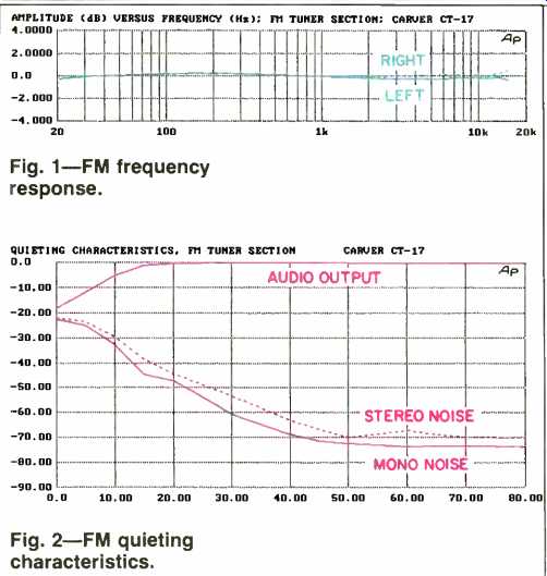
Fig. 1--FM frequency response.
Fig. 2--FM quieting characteristics.
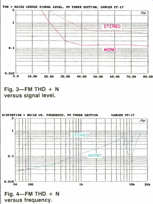
Fig. 3--FM THD + N versus signal level.
Fig. 4--FM THD + N versus frequency.
Figure 1 shows frequency response of the CT-17's FM tuner section. Response at 15 kHz was down a mere 0.2 dB in the left channel and up 0.5 dB in the right. Surprisingly, Carver fails to provide a specification for tuner frequency response; despite this, the response was among the best I have ever measured.
Figure 2 shows FM quieting characteristics as a function of input signal strength. Mono S/N was 73 dB for strong signals; in stereo, S/N was 69 dB at 65 dBf input and increased just a bit further, to 70 dB, for still stronger signals. Fifty-dB quieting required 22 dBf of signal strength in mono (somewhat poorer than the 18.3 dB claimed) and about 25 dBf in stereo.
Figure 3 shows how THD + N varied with signal strength. At 65 dBf, the mono reading was 0.12%, just slightly below Carver's claim of 0.15% (which, I presume, applies to mono for modulating signals of 1 kHz). The result in stereo for an input signal of 65 dBf was 0.39% and decreased to 0.3% at stronger signal levels. This graph also serves to establish the usable sensitivity figure for the FM tuner section, which was 16 dBf in mono and 20 dBf in stereo.
Carver's specifications fail to comply with EIA/IEEE requirements in many respects, not the least of which is a failure to specify THD for stereo and for modulating frequencies other than 1 kHz. I plotted THD + N versus frequency in mono and stereo; results are shown in Fig. 4. Satisfied that there was good correlation between the figures at 1 kHz obtained in these plots and those obtained in Fig. 3, I noted that at 100 Hz distortion was a very low 0.033% in mono and in stereo was 0.4%, as it was at 1 kHz. Just above 100 Hz, however, stereo THD + N rose above 0.4%. At 6 kHz (the other frequency at which THD is supposed to be reported), I obtained readings of 0.45% in mono and 0.5% in stereo.
Figure 5 shows how separation varied with frequency for strong stereo signals. The solid curve represents output from the modulated channel, and the dashed curve shows separation relative to that output level. At 1 kHz, separation was a very high 57.5 dB. I should point out that my test equipment is only guaranteed to provide separation of 60 dB in the signals it generates, so this Carver FM stereo circuit came quite close to the limits of my measurement capability! The separation at 100 Hz was even slightly higher, 59 dB, and at 10 kHz remained well above average, with a reading of 44 dB.
Figure 6 is a spectrum analysis of the CT-17's left and right outputs for a stereo FM input signal whose left channel was fully modulated by a 5-kHz test tone. The spike at 5 kHz for the left channel establishes the reference (0-dB) level for the desired signal; all other spikes represent harmonic distortion components and other spurious signals, such as subcarrier products and their sidebands in the modulated channel. The level of these spurious signals in the unmodulated (right) channel was virtually identical, so this curve was lowered 20 dB for clarity. To read values for the top curve, one should therefore use the left-hand scale; values for the bottom curve should be read using the right-hand scale. In both channels, residual 19-kHz pilot signal was down some 60 dB, and although the sidebands of the suppressed 38-kHz subcarrier are visible at 33 and 43 kHz, the 38-kHz subcarrier component is almost buried in the noise floor of the display. While the overlap of the two curves at 5 kHz conceals the 5-kHz level in the unmodulated channel, it was about 50 dB down.

Fig. 5--FM frequency response (top curve) and separation.
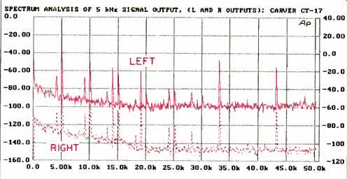
Fig. 6--Spectrum analysis of FM section while a fully modulated, 5-kHz signal
was applied to the left channel only. The right-channel curve has been displaced
for clarity and should be read against the right-hand scale.

Fig. 7--AM frequency response.
I.f. rejection for the FM tuner section was 85 dB, and alternate-channel selectivity was 73 dB. Capture ratio was 2.5 dB, AM suppression was a very satisfactory 60 dB, and image and spurious rejection were both in excess of 90 dB.
Figure 7 is a plot of AM frequency response. Although it did not extend out to 7.5 kHz, as recommended in the National Radio Systems Committee (NRSC) voluntary standard, response was better than average. It extended to nearly 6.0 kHz for the-6 dB cutoff point, more than a full octave better than most AM tuner sections that I've tested.
Preamplifier Measurements
With a sweep signal applied to one of the CT-17's high level inputs, I measured frequency response of the preamplifier circuitry. Results are shown in Fig. 8. Referenced to 0 dB at 1 kHz, response was within ± 0.2 dB from 20 Hz to 20 kHz and was-1.0 dB at 40 kHz.

Fig. 8--Preamplifier frequency response.
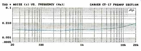
Fig. 9--Preamplifier THD + N versus frequency, at 3 V rms output.
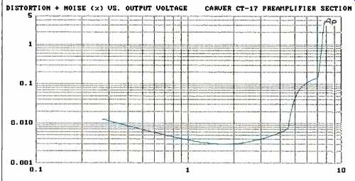
Fig. 10--Preamplifier THD + N versus output voltage for a 1-kHz test signal.

Fig. 11--Spectrum analysis of preamplifier's residual noise, referenced to
an output level of 500 mV.
Maintaining an input regulated to produce a constant 3 V output from the preamplifier, I measured THD + N versus frequency (Fig. 9). At 1 kHz, the reading was 0.004%, well below the 0.015% specified by Carver. In fact, the specified noise level was approached only at the extreme high end of the audible spectrum, 20 kHz, where harmonic distortion is irrelevant. Figure 10 is a plot of THD + N versus output level, using a 1-kHz test signal. Carver lists the rated output of the preamplifier as 6.0 V, but I presume they mean this is the maximum output voltage since at that level, distortion was just over 0.1% and rose rapidly above 7.0 V.
Signal-to-noise ratio for the high-level inputs was 90.2 dB for the left channel and 91.2 dB for the right. Here, Carver chose to specify S/N in an unorthodox manner, referencing the S/N value to an output of 1.0 V. The standard method of measurement uses a reference input of 0.5 V, with the master volume control turned down to produce an output of 0.5 V, or unity gain in the case of a preamplifier. A reading of 90 dB or better using this standard method is superb for any preamplifier, so I wonder why the manufacturer used a higher reference level so as to be able to claim S/N of 95 dB. Figure 11 is a spectrum analysis of the residual noise at various frequencies. As. you can see, the only significant noise peaks were those associated with the power-line frequency of 60 Hz and its harmonics. Even the worst of these was down more than 90 dB with respect to 0.5 V output.
For phono S/N, Carver also strayed from the standard measurement method. Here, the company referenced the reading to 1.0 V output instead of 0.5 V. Although this method yielded a published specification of 80 dB, the correct method resulted in S/N readings of 82.4 dB for the left channel and 81.8 dB for the right. Again, these are superb figures for an MM phono input, and I can't imagine why Carver resorted to their own reference levels.
Figure 12 shows loudness compensation characteristics of the preamplifier with volume-control settings ranging from maximum to-40 dB, in 10-dB increments. Happily, Bob Carver and his engineers understand the requirements of proper loudness compensation for low-level listening and have refrained from incorporating treble boost in their loudness circuitry. Figure 13 shows the maximum boost and cut range of the bass, midrange, and treble controls. Action of all three tone controls conformed very closely to the published specifications.
Sensitivity for the high-level inputs was 75 mV for 0.5 V output; for the phono inputs, 1.05 mV of input signal at 1 kHz was required to produce that same output level. Figure 14 shows how the phono equalization circuitry handled RIAA playback. The plot shows deviation from the RIAA curve versus frequency. Equalization was virtually perfect from 1 kHz upward, but it was off by an almost constant + 1.0 dB from 200 Hz downward.
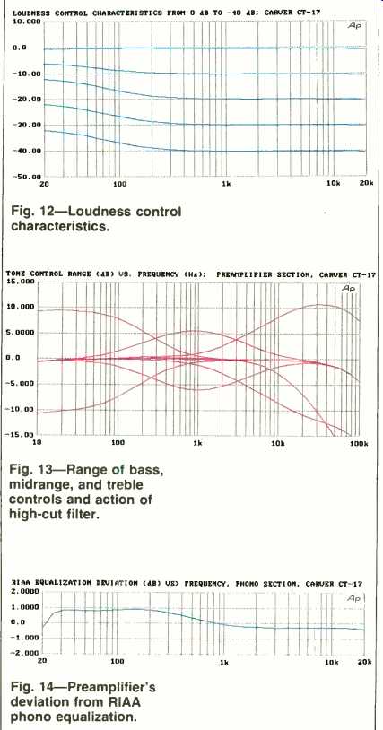
Fig. 12--Loudness control characteristics.
Fig. 13--Range of bass, midrange, and treble controls and action of high-cut filter.
Fig. 14-Preamplifier's deviation from RIAA phono equalization.
Use and Listening Tests
Some years ago, I tested one of the first Carver tuners to employ his ACCD circuitry. The circuit behaves in much the same way in this latest version. Without ACCD activated, I was able to pick up 48 FM signals using my outdoor antenna. Some 44 of these were received as stereo signals, but of these, six were so noisy that I normally would have had to listen to them in mono. Using ACCD, four of the six became quiet enough to enjoy in stereo. Now, when I say these signals became usable "in stereo," I recognize that's a bit of a misstatement; the L-R component in this case is a combination of the true L-R and a simulated L-R created by the ACCD circuitry. Still, it sounds like good stereo and imaging, and I'd rather listen to this signal manipulation than to an intolerable level of noise and static.
My judgment of Sonic Holography remains the same as it's always been: The system works well so long as you remain at or very close to the so-called "sweet spot." You may also find, as I did, that some repositioning of your speakers is necessary to take full advantage of this feature.
For my listening tests I played a couple of new CDs released by Telarc. The first (CD-80219) contains a couple of Mozart piano concertos (including the familiar No. 21 in C major, from which the Elvira Madigan theme music was taken). I must say that the Carver CT-17, hooked up to the rest of my reference system, introduced no noticeable coloration. This, after all, is what is expected of a good preamplifier-signal control without signal degradation.
The Cincinnati Pops, under the direction of Erich Kunzel (CD-80223), provided my other listening fare. In this unusual disc, Doc Severinsen, the trumpeter and band leader of The Tonight Show, demonstrates that his musical talents extend to the classical, as he plays various arias in which the sound of his trumpet replaces vocals. I've found that a trumpet, played properly, can serve as an excellent program source in evaluating audio components for absence (or presence) of many forms of IM distortion. Happily, the Carver CT-17 exhibited none of these, and the music came through sounding much the same as it did when my reference CD player was hooked directly to my reference power amplifier.
Perhaps even more interesting, a few other listeners and I could detect no difference in sound quality (other than a very tiny shift in level) when I switched from "CD" to "CD Direct." Although I did not take the time to hook up separate listening zones to take advantage of the CT-17's ability to provide different program material to two different locations, I evaluated this feature on the test bench; it worked exactly as claimed. I did check out the Dolby Pro-Logic circuitry, however, and it worked perfectly.
A final word is in order concerning the owner's manual. It is written in the friendly and easy-to-understand manner that is so typical of Bob Carver's style. Each section of the manual is complete unto itself and offers step-by-step instructions that are easy to follow. There's a message from Carver himself, near the front of the book (along with a photo of this audio enfant terrible hovering over an open chassis full of electronics). Here, he describes the CT-17 as a "high quality 'straight wire' preamplifier with extremely low distortion and noise." I couldn't have summarized its attributes better myself.
-Leonard Feldman
(Source: Audio magazine, Dec. 1990)
Also see:
Tandberg TCA 3018A Preamp and TPA 3026A Amp (Apr. 1987)
Vendetta Research SCP-2B Pre-Preamp (Dec. 1990)
= = = =