In this age of solid-state devices, it is unusual to find a constructor who
still resorts to high-quality commercial practice to produce a high-power
amplifier. This unit seemed to have sufficient merit to warrant the full
treatment, and all seasoned audio buffs know that superb performance can
still be obtained from vacuum tubes.
By Robert M. Voss and Robert Ellis, Photographs by Edwin F. Meers
This article appeared originally in Audio, October 1966.
Transistors may be here to stay, but tubes are not yet ready to be written off and placed in muse ums. The amplifier described here was designed and constructed to see just how far vacuum-tube design has progressed; it is a state-of-the-art device.
Before you read further, a word of caution: if you are interested in com pact or miniaturized equipment, this is not for you. The amplifier and power supply are each built on 13” × 17” chassis, whose combined weight is over 80 lbs. The construction of the power sup ply (about 55 lbs) required installation of a small hydraulic jack underneath the workbench to avoid sag and ultimate collapse of the bench. Those who look upon the amplifier marvel greatly; their awe is brought about by the over all massiveness and, particularly, by the size of the power transformer, which by normal home standards is immense, although it would not hold a candle to some units in professional installations.
BASIC AMPLIFIER CIRCUIT
The basic amplifier circuit (Fig. 1) is, up to the output stages, an adaptation of a Genalex design, and a number of its features are deserving of further comment. First of all, the RC networks between C3 and C4 and R14 and R15 are there for the purpose of rolling off response at both frequency extremes to avoid any tendency toward motorboating or high-frequency oscillation at the resonant frequency of the output trans former and associated circuitry.
Incorporation of a driver stage between the phase-splitter and power-amplifier stages, in addition to supplying some needed gain, isolates the output stage from the shaping circuits and allows both output tubes to be driven by sources of the same impedance.
Circuits that drive the output stage directly from the paraphase inverter may overload asymmetrically, because, although in schematic form this type of inverter tends to look completely sym metrical, such is not at all the case. The top half of the inverter is a simple voltage amplifier with no voltage feedback, while the bottom (the half which is actually the inverter) is a voltage amplifier with sufficient feedback to reduce its gain to unity and its output impedance to a comparatively much lower value.
Because of the large amount of drive needed for the output stage, the plates of the drivers are fed from the same 650V source as is the output stage. Very large coupling capacitors are used to the output stage to hold rolloff and con sequent phase shift to a point well below the frequency determined by the earlier shaping networks.
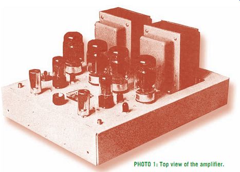
PHOTO 1: Top view of the amplifier.
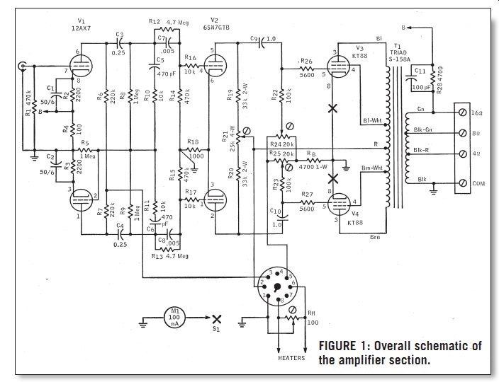
FIGURE 1: Overall schematic of the amplifier section.
THE POWER SUPPLY
Aside from these few refinements, the circuit is very straightforward, and this leads to ease of adjustment and a large stability margin, in addition to generally superior performance. One possible source of difficulty, however, was the large swing in plate current drawn by each output tube from 50mA at zero signal to 150mA at 100W output per channel.
To accommodate this variation (equivalent to a total amplifier drain of about 250mA idling and 650mA at 200W out) we have used a silicon rectifier feeding a choke-input filter (Fig. 2).
The rectifier (Sarkes-Tarzian S5162) is meant as a tube replacement, and was the most economical way of meeting the current and peak-inverse-voltage requirements. (Strings of lower-voltage diodes, with voltage-equalizing rc networks would have cost about the same, and are a makeshift solution at best.) Those with a real aversion to solid state components can use push-pull 5R4GYs in place of the silicon rectifier: this will reduce power output some what because of both larger initial voltage drop and poorer regulation. In addition, it will require redesign of the physical layout of the power supply since 5R4GYs cannot be expected to live very long underneath a chassis.
The power transformer and chokes are rated at 400mA continuous output, which means that the power supply runs at a comfortably low temperature, even after many hours of operation. If you are testing the amplifier for maximum output, or running it at high power for any other purpose, replace the ½ A B+ fuse with 1A for the duration of the test, and avoid driving it at sustained full power for more than ten minutes or so.
This does not mean that the power supply has an inadequate safety margin: quite the contrary, the amplifier is quite suited to fill your living room (or major league baseball park) with large amounts of sound for indefinite periods for a long time. When initially wiring the power supply, test the filament windings to make sure they are in phase rather than bucking by momentarily touching the red leads (thick ones, not the thin red high-voltage leads) to the green; if you get a fat spark (only 6V here, no shock hazard) they are out of phase; reverse one set of leads and solder.
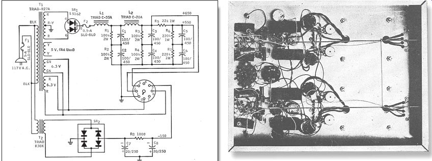
FIGURE 2: Schematic of the power-supply section.
PHOTO 2: Under-chassis view of the amplifier, showing relatively neat construction.
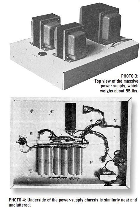
PHOTO 3: Top view of the massive power supply, which weighs about 55
lbs.
PHOTO 4: Underside of the power-supply chassis is similarly neat and uncluttered.
BIAS-SUPPLY TRANSFORMER
Since the power transformer has no bias winding, a separate transformer is used for the bias supply. Any isolation transformer will do as long as it can de liver about 15mA; the exact output voltage is not critical since it is adjustable at each tube. If you can't locate a pack aged bridge rectifier, just about any four silicon diodes will work just as well.
Photo 1 is the top view of the amplifier; each channel is on one side of the chassis, with the common components (meter and switch) in the center. Hidden behind the output transformers are the output terminal strips.
The male octal power connector is on the far side of the chassis, the hum balance control on the near side. The two other capped potentiometers (between the 6SN7s and pairs of KT88s) are the AC balance controls.
Photo 2 shows what the amplifier looks like underneath. There are plenty of components used in the input stages, but the large chassis leaves plenty of room. Just make sure nothing is touching that isn't supposed to touch. The locations of the meter and switch are obvious. The four large capacitors are the coupling to the output stage; the balance controls are between them. The four bias pots are on the other side of the output tube sockets. Two bus bars are used, to which all grounds are connected; they are tied together and grounded to one of the input sockets; this is the only chassis ground.
The top of the power supply is shown in Photo 3; the only components here are the power transformer and chokes, the octal power connector, and the line cord. More is to be seen underneath (Photo 4). On the lower right are the components of the bias supply: trans former and (partly hidden) R8, R2, C7, and C8. The B+ rectifier is mounted on an angle; there is no need to put it on top of the chassis since its life is indefinite. Underneath the rectifier is the high-voltage fuse; underneath the fuse are all of the resistors and capacitors in the high-voltage circuit.
The output of the power supply is fed to an octal socket; a matching cable is used to deliver power to the amplifier.
Hookup is by means of a six-conductor cable. Since the total filament drain is over 8A, the two wires carrying filament current should be at least #18; the others can be #22. We used Belden 8446, whose #22 conductors are rated at only 200V, but as in other applications, we have had no difficulty with insulation breakdown at many times this rating.
Perhaps lacing six single, well-insulated wires might be a more elegant solution; in any case keep the length to no more than is necessary.
==========
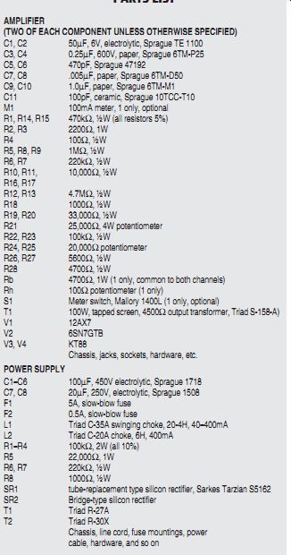
TABLE 1
PARTS LIST
AMPLIFIER
(TWO OF EACH COMPONENT UNLESS OTHERWISE SPECIFIED)
C1, C2 50µF, 6V, electrolytic, Sprague TE 1100 C3, C4 0.25µF, 600V, paper, Sprague 6TM-P25 C5, C6 470pF, Sprague 47192 C7, C8 .005µF, paper, Sprague 6TM-D50 C9, C10 1.0µF, paper, Sprague 6TM-M1 C11 100pF, ceramic, Sprague 10TCC-T10 M1 100mA meter, 1 only, optional R1, R14, R15 470k-ohm, ½W (all resistors 5%) R2, R3 2200 ohm, 1W R4 100 ohm, ½ W R5, R8, R9 1M ohm, ½W R6, R7 220k-ohm, ½W R10, R11, 10,000 ohm, ½W R16, R17 R12, R13 4.7M ohm, ½W R18 1000 ohm, ½W R19, R20 33,000 ohm, ½W R21 25,000 ohm, 4W potentiometer R22, R23 100k-ohm, ½W R24, R25 20,000 ohm potentiometer R26, R27 5600 ohm, ½W R28 4700 ohm, ½W Rb 4700 ohm, 1W (1 only, common to both channels) Rh 100 ohm potentiometer (1 only) S1 Meter switch, Mallory 1400L (1 only, optional) T1 100W, tapped screen, 4500?output transformer, Triad S-158-A) V1 12AX7 V2 6SN7GTB V3, V4 KT88
Chassis, jacks, sockets, hardware, etc.
POWER SUPPLY
C1-C6 100µF, 450V electrolytic, Sprague 1718 C7, C8 20µF, 250V, electrolytic, Sprague 1508 F1 5A, slow-blow fuse F2 0.5A, slow-blow fuse L1 Triad C-35A swinging choke, 20-4H, 40-400mA L2 Triad C-20A choke, 6H, 400mA R1-R4 100k-ohm, 2W (all 10%) R5 22,000 ohm, 1W R6, R7 220k-ohm, ½W R8 1000 ohm, ½W
SR1 tube-replacement type silicon rectifier, Sarkes Tarzian S5162 SR2 Bridge-type silicon rectifier
T1 Triad R-27A
T2 Triad R-30X
Chassis, line cord, fuse mountings, power cable, hardware, and so on
===========
TESTING AND OPERATION
Before connecting the amplifier to the power supply, make a preliminary resistance check from pins 2, 3, 5, 6, and 8 of the male octal power connector on the amplifier to ground. Pins 2 and 3 should be wide open (infinite resistance), pin 5 about 10k, and pins 6 and 8 varying from 100 ohm to zero as the hum balance control is rotated.
When measuring from pin 5, turn all four bias controls from one end of rotation to the other and make sure this has no effect on the resistance to ground at pin 5. Failure to make this check cost us a KT88: a sliver of wire caught under one of the bias pots removed all bias from that tube, and before we could get to the power cord, completely stripped the cathode of the tube. Any such short would show up as a resistance variation in the above check.
Assuming that the amplifier checks out, plug in the power supply with the amplifier not yet connected (the dimming of lights is normal) and measure the output voltages (B+ should be about 700V with no load). If everything is normal, unplug the power supply and connect it to the amplifier. With the 12AX7s and 6SN7s in their sockets (no output tubes yet) plug the power supply in again and make sure the tubes light up.
If you wish to make plate voltage checks here, keep in mind that they will be a bit higher than normal. Connect a signal generator to one of the in puts (about 1kHz) and adjust it for about 20V at pin 5 of either of the output tubes of that amplifier. Now adjust R21 so that the signal will be the same at pin 5 for both output tubes. Repeat the adjustment for the other amplifier; we used caps on the balance controls since this is a semi-permanent adjustment which cannot be checked on the meter.
Now connect each side of the amplifier to a dummy load (or a common load to the paralleled outputs), turn each bias control fully negative (counterclockwise in our amplifier) and plug in the output tubes. To check output-tube current, we used a 100mA meter with a switch which inserts the meter into any one cathode circuit or cuts it out of the circuit. If you see no purpose in building into the amplifier a meter which will be used rarely, make some other provision for measuring cathode current (such as closed-circuit phone jacks).
In any case, with the controls supplying full bias, the tubes should draw little or no current. After they have warmed up, slowly adjust each bias pot for 50mA cathode current. Since they interact, go back and adjust each pot a couple of times until all of the tubes are drawing the same 50mA. After about ten hours of operation, repeat the adjustments to compensate for initial aging.
Before connecting the amplifier to your speaker system, check each side with a voltmeter (dummy load attached) to make sure it is not oscillating; if you have made a wiring error causing the feedback phase to be re versed, the amplifier would be producing about 160W of oscillation, which you will need to correct before it sends your speaker up in smoke.
Adjustment of the amplifier is now completed. If you have the test equipment, you might choose to trim balance controls R21 for minimum IM distortion; adjustment for equal output is sufficient for anything less than laboratory measurement uses.
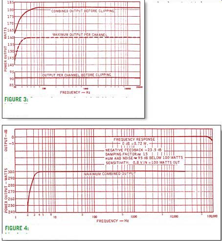
FIGURE 3: Curves of output of each individual section before clipping,
and of both sections together, along with maximum output per channel,
all versus frequency.
FIGURE 4: Frequency-response curves for 0.72W per channel, and for maximum combined output of both channels.
PERFORMANCE
Frequency response, power output, and other data are given in Figs. 3 and 4. No distortion measurements are given since these have been shown (by transistor research, to a great extent) to have little to do with sound quality. Suffice to say that square waves at 1kHz and 10kHz are closer to the original than those coming out of any other amplifier we have seen. 20Hz square waves show a great deal of tilt because of subsonic rolloff, and high-frequency square waves are rounded because of the high-frequency rolloff.
Note the large difference between maximum output before clipping and absolute maximum output in both the single channel and combined measurements. This is indicative of the symmetrical, gradual clipping which turns sine waves almost into square waves before sides are deformed. Maximum power without audible distortion is about 100W, music power about 115W (each channel), and the total peaks in the half-kilowatt region.
Frequency response is dead flat throughout the spectrum, another 15dB of feedback will produce neither oscillation nor detectable sound improvement, the noise is inaudible, the gain is very high (input gain controls may be needed in some applications), and the damping factor (remember that?) is good for most speakers. The amplifier has been tested into a capacitive load approximating an electrostatic speaker and shows no signs of instability or sound degradation.
A word of caution: if you have never experimented with anything this big, be very careful about plugging and un plugging leads. An open ground could easily mean 160W at 60Hz fed to your speaker. Also, switching clicks may contain so much energy that they may cause your house lights to flicker. This does not mean oscillation; it simply means that the amplifier can reproduce a sharp thump fed into it at the equivalent of many watts of power. If you have chronically noisy switches on your pre amp, you might consider an infrasonic filter.
RATIONALE
Why, to sum things up, should you go out of your way to listen to an amplifier whose only claim to fame seems to be the great gobs of power it can produce, an amplifier whose flat frequency response, low noise, and high gain can be duplicated by most of the commercial units on the market today, an amplifier which is hardly easy on the back muscles and which, if mistreated, may vent its rage by destroying any speaker made in a fraction of a second? The reason is sound. For pure sound quality, this amplifier sounds notice ably better than anything we have ever heard. Using it in place of a respected 70-watter elicited immediate comments from listeners. Not only is it exception ally clean at normal levels, but the feeling of completely unlimited power handling capacity is a new experience.
We invariably listen to the amplifier at considerably higher levels than be fore, but it is a new type of loudness, absolutely free of listener fatigue and truly approaching live sound. This is an amplifier that can be relied upon never to call attention to itself (sonically, at least) no matter what it is called upon to do; it will always be a strong link in the chain of sound reproduction.
----------------------
Also see: