What does it take to build a successful line stage? This author shares
his design experience to show you how it's done.
By John L. S.
Many line drivers have claimed and sometimes delivered better performance. Here is another look at the problems encountered on the way to a circuit able to drive both terminated 600 ohm transmission lines or a length of high capacitance audio cable.
Each of the two amplifiers in this article has its own unique problems, the most important of which I have investigated in some detail.
THE OUTPUT STAGE
Among several possibilities, there appear to be two favorite topologies. One of them is in fact a power-amplifier stage, usually a triode with a grid driven by a transformer. The other is some kind of single triode or a pair of twin tri odes connected in a variation of the so called mu follower.
The first of these is well able to drive either of the loads I've referred to. however, at high levels it may deliver more distortion than you can tolerate. It also tends to be an expensive solution, since it needs two wideband transformers.
The second may be adequate at low levels driving a short piece of audio cable, many of which bring with them 30pF per foot of capacity. It doesn't take a rocket scientist to realize you will soon have more capacity than is practical for the mu follower to drive. It will go into overload quickly as the current limits of the upper and lower triodes are reached, and this will limit the circuit's ability to drive either capacitive loads or a terminated 600 ohm transmission line.
-------------------------

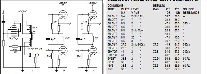
TABLE 1: RESULTS OF POWER STAGE-300V POWER SUPPLY
*Driven by 6SN7. See text.
-------------
FIGURE 1: Line drivers.
------------
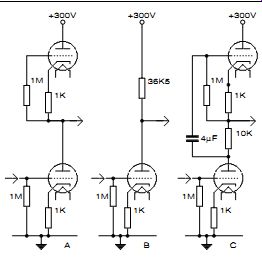
FIGURE 2: Some mu followers.
THIS MIGHT WORK
Instead of the usual triode working into an output transformer, I tried some thing different (Fig. 1A). The circuit appears to be somewhat unusual, but it is able to drive commonly encountered loads with authority.
Using a common triode (or triode-connected pentode), the signal is driven into a split-primary audio output trans former that was originally meant for a push-pull amplifier. The 600 ohm output is taken from one of the 43% ultralinear taps, which results in a load of 13k ohm reflecting back to the triode.
All the curves showing distortion in triode versus load impedance tell us that distortion increases as load impedance diminishes. In a power stage, you design for a load impedance that is at least twice, and more often three times, the plate resistance. A triode-connected 6K6GT used at this stage (I tried) has a published plate resistance of 2.5k-ohm (at 250 plate volts). Thus the plate load is five times the plate resistance, and low distortion is guaranteed.
There are other advantages to this split connection. It provides local negative voltage feedback of half the total output signal, which further reduces both the residual distortion and the driving resistance as seen by the load. The output capacitor only needs to be low voltage, but nevertheless of good quality.
You must take care with the primary connections to achieve proper phasing.
Otherwise, no output will result. You do not normally use the secondary, al though it could provide a second over all feedback path when properly connected. You would connect feedback from the secondary to the cathode of the input stage. If the output-signal level increases, you need to reverse the transformer secondary connections.
The secondary can also directly drive a loudspeaker with ease.
Audio power transformers with split primaries are not common, but Hammond, Sowter, and others can easily provide these. If you have a transformer specially made for this application, it should have an air gap, since the circuit is not balanced for DC, and core saturation could be a problem. The transformer I had on hand for this project is a Japanese device I acquired around 1960 with the intention of using it in a push-pull power amplifier where in the DC would be cancelled. It seems to have enough iron so that I had no core-saturation problem. Nominal impedance of this transformer is 8k ohm.
A COMPARISON
In order to get comparative data, I tried a mu follower line stage using several different biasing conditions (Fig. 1B). I used a 6BL7GT, since it is able to deliver a large output if properly utilized. I provided bias for the first condition with 100 ohm biasing resistors, which resulted in a standing plate current of 9.4mA. I set another condition using cathode resistors of 200 ohm, which yielded a standing current of 8.5mA (Table 1).
Distortion measurements were made using a Pico Technology ADC-100 analogue to digital converter. The signal source was an HP 200CD oscillator.
Clipping begins at 7.5V RMS when driving a 1.2k ohm load.
With a pair of 6BL7GTs (one each for the upper and lower triodes), these results could be directly related to a 600 ohm load.
Performance is reasonably good, although it could use some help. Since the load is less than the plate resistance at this operating point, you'd think the distortion would be high. The answer appears to be that at 2V RMS only a 1.67mA AC (4.71mA P-P) signal is required in 1.2k ohm. That is still a large part of the 9mA standing current. Not shown in the test results is an ominous rise in higher-order harmonic distortion.
If the 6BL7GT were run at a higher plate current, the results would be better, but you would need to increase the plate-voltage supply to satisfy the voltage drop across the 20k resistor. Alter natively, you could reduce this resistor, but then distortion would increase.
I tried a third condition wherein the standing current was increased to 27mA (Fig. 1C). Notice the 20k resistor driving the upper grid was reduced to 1k-ohm. This causes the source resistance to increase to 555 ohm.
By replacing the 6BL7GT in Fig. 1C with a 6BX7GT, I established a fourth condition. The increased plate current resulted in a further improvement of the test results. Finally, test results of the split-load line stage are included in the test data for comparison (see Table 1 en tries for 6V6GT).
THE INPUT STAGE
From the beginning of this project, I had intended to use a mu-follower as the input stage because of its reported low distortion and large voltage-output capabilities. On the way to the final circuit, I came upon some not-well-documented shortcomings of the simpler versions of this circuit.
In its simplest form, the mu follower uses identical triodes in the upper and lower parts. These are equally biased in order to make available the largest possible voltage to each of the triodes so that you can realize maximum voltage output. At this point, I used a 6SN7GT with 1k ohm biasing resistors, resulting in a plate current of 4mA so that good bandwidth could be ensured. The plate curves of the 6SN7GT show the plate resistance to be 10k-ohm under these conditions (Fig. 2A).
Using the formula for calculating plate resistance with cathode feed back, the operating plate resistance with a 1k-ohm cathode resistor is 30k-ohm.
That would seem a worthwhile improvement as the plate load for the lower triode. However, the lower half has also gone to 30k-ohm, which sets up the condition where the load is one times the plate resistance.
When you treat the upper and lower triodes equally, the only advantage appears to be the low driving impedance available at the upper cathode. That would be useful if this stage were driving the transmission line.
The upper triode will always present to the lower triode a load equal to its own plate resistance. As well, that load will be the nonlinear curve of the upper triode's plate characteristic, guaranteeing that you will always have more distortion than need be.
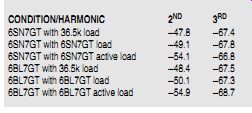
TABLE 2
RESULTS OF DISTORTION MEASUREMENTS AT 10V RMS OUTPUT
CONDITION/HARMONIC 2ND 3RD
6SN7GT with 36.5k load -47.8 -67.4
6SN7GT with 6SN7GT load -49.1 -67.8
6SN7GT with 6SN7GT active load -54.1 -66.8
6BL7GT with 36.5k load -48.4 -67.5
6BL7GT with 6BL7GT load -50.1 -67.3
6BL7GT with 6BL7GT active load -54.9 -68.7
OTHER TESTS
I made a further test of this conclusion by inserting in the plate circuit a 36.5k-ohm resistor in place of the upper tri ode (Fig. 2B). This maintained the same operating conditions for the lower tri ode so that a valid comparison was possible. I measured distortion at 10V RMS on both circuits (Table 2). The resulting driving impedance of this configuration is 16.5k-ohm (36.5k-ohm plate load in parallel with 30k-ohm plate resistance), which is more than adequate to drive the output line amplifier.
In another test, I substituted a 6BL7GT into the circuit. The results indicated that the simplest form of the mu-follower circuit has little or no ad vantage aside from a reduced source impedance for the following stage over a plate-load resistor. I also concluded that a high-perveance triode such as a 6BL7GT is little better than an ordinary triode such as a 6SN7GT when operated at the same plate current.
In a final test of this part of the circuit, I inserted a 10k-ohm resistor between the two triodes (Fig. 2C). Driving the upper grid with the signal developed across this resistor makes the upper tri ode an active current source. The result is a load of considerably higher resistance for the lower triode. Measurements showed the new active load for the lower triode to be 210k-ohm. The measured distortion was about 6dB less than the simple load-resistor case.
Some of the differences shown in the test results are within the error range of the test equipment. The 6BL7GT may be 1dB better than the 6SN7GT. The circuit using the active current source is a definite improvement. I settled on the 6SN7GT because of its availability and good performance in the active current source version, while its power requirements are modest.
In summary, the mu-follower output line-stage advantages are simplicity, no output transformer, and gain in the output stage. The advantages of the split load output line stage are very low output impedance, very low distortion, and the ability to drive a loudspeaker directly.
THE FINAL CIRCUIT
This article should allow you to make a choice of which circuit best fits your needs. I chose RC coupling in the split load version (Fig. 3), which lets each amplifier stage work where it functions best. V1 is a 6SN7GT, but a 6BL7GT works just as well. Any medium-mu triode such as a 12AU7, 5814, or 5687 would do.
V2 in the final circuit is a 6V6GT. A 6K6GT also works well, as would sever al other triode-connected pentodes and common triodes. Plate-power rating is an important consideration here. The tube you use needs to dissipate about 10W with a 300V power supply, and plate current should be around 30mA.
You can make an adjustment by varying the 330 ohm cathode resistor. The primary resistance of the transformer's winding forms part of the biasing circuit for this stage.
Performance of the complete split load version is summarized in the *6V6 entries of Table 1. A comparison of the results with those for the 6V6GT show a small but measurable distortion reduction. It seems that some distortion cancellation is at work here between the 6SN7GT and the 6V6GT.
"ENHANCED TRIODE" POSTSCRIPT
During development of the line amplifiers there was a requirement for tube specifications not obvious from those published. This led me to utilize simple circuits to measure them. I de rived some information from data in the published curves, and I describe both methods.
Accurate measurement of tube parameters normally involves the application of some rather complicated bridge circuits. The methods I describe are more convenient for the average experimenter, and the results obtained are ac curate enough for the analysis here.
On one of the line amps, I tried a direct connection from the upper cathode of a mu stage to the screen grid of the output stage, hoping this would provide DC coupling and eliminate a few parts. The result was disappointing, but it also led to some interesting conclusions with regard to the so-called "enhanced triode" mode.
Performance of the circuit while the output stage was connected in the enhanced-triode mode indicated low transconductance (Gm) through grid 2, so I decided an investigation of grid-2 Gm was in order. From the performance of the circuit, I knew grid-2 Gm was low, but how low?
GM AND PLATE RESISTANCE FROM THE CURVES
Several pentodes and beam tetrodes listed in various RCA tube manuals show screen grid versus plate curves wherein you can directly calculate the Gm and plate resistance. For example, on p. 320 of RC-19 for the 6973, you can see that when the screen voltage is stepped in 50V increments, the plate current changes about 30mA.
Since Gm is measured in mA/V, you need only to divide, and in this case the result is 0.6mA/V. Compare that to the Gm through grid 1, which under similar conditions is 4.8mA/V. That is not very enhanced.
The plate resistance is the same whether you're looking at the curves for grid 1 or grid 2. That is easily seen by inspection of the two graphs. Another way of considering this is to realize that plate resistance is change of plate voltage versus change of plate current (Ohms law). Plate-resistance specifications are always given with the grids held constant.
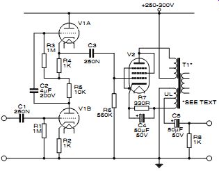
FIGURE 3: Line amplifier.
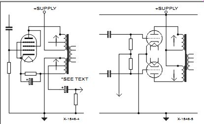
FIGURE 4: Split load.
FIGURE 5: Push-pull.
--------------------
SPLIT LOADING
Some confusion may arise when you try to understand how to connect a split-load trans former. A comparison with the common push-pull stage will help, since it uses a similar output transformer. Winding polarity is indicated by dots (Figs. 4 and 5).
First, you can make the common assumption that current runs downhill, which helps a lot, even as it does for those working in the semiconductor industry.
In Figs. 4 and 5, the arrows indicate the commonly assumed direction of current flow, from positive to negative. In the case of the push-pull circuit, these currents are as equal as possible and running in opposite directions so that they will cancel most of the DC flux in the transformer core.
Not so in the split-load connections. Flux resulting from current in the two parts of the transformer winding is additive and may result in core saturation. You need a core with a built-in air gap, just as if you were dealing with a single-ended amplifier.
Again referring to the push-pull circuit, for a useful output to occur, you'll need as nearly as possible equal but opposite voltages at each end of the transformer primary.
Since the grids are driven equal and opposite, that condition will result.
The same conditions are needed in the split-load circuit to produce an output. When the tube is turned on by a positive-going signal on its grid, the plate will go negative, while the cathode goes positive in order to follow the grid. A useful output occurs.
--------------------
If the operating conditions are those published for 250V plate and screen, then plate resistance is about 73k-ohm. That won't provide much damping for a loud- speaker in an enhanced-triode connection anymore than it would as a straight beam tetrode. You'll need to apply negative-voltage feedback to gain control.
Another example of a tube which could provide power and lots of it in an output stage is the 6DQ5 (see pp. 198-199 of RC-19). The upper part of the curves would seem to indicate a Gm of 6.8mA/V at grid 2, but you would never go there in a real audio circuit. Plate dissipation in the upper part of the graph exceeds 100W. These tubes were designed for sweep circuits, where they endured either large voltages or large currents, but not at the same time. At a more realistic operating point, the grid-2 Gm drops to 4mA/V. Compare that to 10.5mA/V as a beam tetrode.
I used many of these as pulse generators in a core-memory research pro gram in 1960. When driven hard, they are able to produce 1.5A pulses with rise times of 30ns into a 50 ohm transmission line, but only for microseconds.
Again the plate resistance is the same whether you apply the signal to grid 1 or grid 2. From the curves in the safe operating region, this appears to be about 4k-ohm, which is a long way from what you can obtain from a 2A3 or 300B. You will again need some negative-voltage feedback here to get control of a speaker load.
The only real advantage of the enhanced-triode mode appears to be the large plate-dissipation ratings of the tubes used. That is the bottom line when it comes to power.
TESTING FOR GM AND PLATE RESISTANCE THROUGH GRID 2
I used the circuits of Figs. 6 and 7 to measure the Gm and plate resistance of some tubes wherein the screen is the driven element. In each case, you need two separate power supplies isolated from one another. For this test, I used as the plate supply a regulated vacuum-tube power supply I had built about 1960.
For the screen, I needed to simulate conditions as they would be in the pro posed enhanced-triode mode. I connected 17 9V batteries in series, which provided 158.6V-about the DC voltage available at the upper cathode of the input stage previously described. For these tests, current from the screen supply is small and intermittent, a technique that worked well. You must be sure to apply the plate voltage be fore the screen. The screen should never be left on alone.
Grid-1 bias was provided by one, two, three, or four 9V batteries as needed.
The 250nF capacitor on grid 1 is a noise bypass to ground.
-------------------------
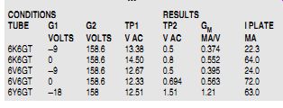
TABLE 3: MEASUREMENT OF GM WITH GRID 2 AS CONTROL
---------
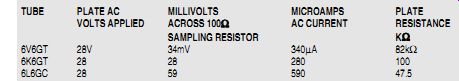
TABLE 4
MEASUREMENT OF PLATE RESISTANCE
---------------
GRID-2 GM
Referring to Fig. 6, I first applied a 300V potential (PS1) to the plate of the tube under test. I connected a 1kHz audio signal to grid 2 through the grid-2 battery (PS2) and measured it with a DMM or oscilloscope. At the same time, I measured the resulting AC voltage developed across the 100 ohm current-sampling resistor.
The reason for the double power sup ply becomes obvious here. You need to isolate the screen current from the measurement. You should measure only the plate current, since it is the change in that versus the voltage change at grid 2 that you need.
Measurements taken while grid 1 is at 0V must be performed quickly to avoid overheating the tube. Results obtained for various tubes are shown in Table 3. All of the results are poor for a power tube.
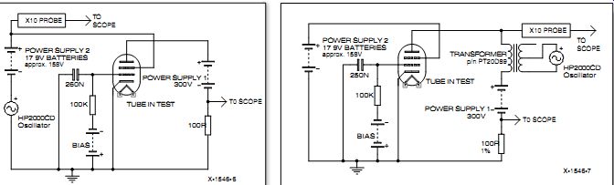
FIGURE 6: Grid-2 Gm.
FIGURE 7: Plate resistance.
GRID-2 PLATE RESISTANCE
Note the similarity of Fig. 7 to the circuit of Fig. 6. Plate resistance is a measure of the result of changing plate voltage on the plate current. In pentodes and beam tetrodes, the plate resistance tends to be high, and for this reason the driving signal must be large to produce a measurable change in the plate current. The audio oscillator is again at 1kHz, but this time applied through a step-up transformer.
The transformer also isolates the audio oscillator from dangerous voltages. The transformer I used here is available as part number PT-20D89 from Antique Electronic Supply, 6221 S. Maple Ave., Tempe, AZ 85283, 602 820-5411.
Plate-resistance results appear in Table 4. Note here that, aside from biasing, grid 1 shows up nowhere in the measurements, yet the plate resistance looks nothing like a triode. The measured results are not indicative of common audio triodes, enhanced or otherwise.
If you were to plot the plate family of curves with grid 2 as the variable, they would look very much like those of a zero-bias Class B triode, well known in RF-transmitter circles.
EQUIPMENT USED
HP 200CD Oscillator
HP 302A Wave Analyzer
GN GAG-810 Oscillator
Rohde & Schwartz BOL 4 Trace 100MHz Scope
RS 22-168A DMM
Sanwa AX 303-TR Analogue Multimeter
PicoScope ADC-100 Virtual Instrument
Electronic Workbench Software
----------------------
Also see: