This high-quality design addresses the drawbacks traditionally
associated with attenuator layouts.
By R.K.S.

In the early days of moving-coil loudspeakers, builders would place drivers into a baffle board giving little or no consideration to the enclosing cabinet. Later, in an attempt to improve low frequencies, they devised ever larger cabinets to keep the acoustic radiation-coming from the rear of the speaker-from en countering the front radiation. Only in the 1950s did a speaker company, Acoustic Research (AR), think of designing the speaker and cabinet in concert-no longer was the cabinet an afterthought.
ADD-ON SOLUTIONS
The phrase "high fidelity" originally referred to a sound system's ability to re produce high frequencies. To achieve this, many speaker builders simply "added on" a high-frequency driver.
Later, in an attempt to improve power handling, they added a capacitor to the tweeter. Only much later were crossovers introduced at the design stage as an integrated feature of the speaker system.
Biamping still has that add-on feel about it. Often, designers simply add an extra amplifier and subwoofer to a speaker system to improve the lows, much as the tweeter was added in the '40s to improve the highs. Alternatively, you can separate the lowest-frequency driver, usually the subwoofer or woofer, and amplify that separately in an existing sound system. Only the ActiPass Crossover System (SB 8/00) is a fully integrated active-passive crossover system with nothing added on.
In order to improve power handling and lower distortion at a given sound pressure level (SPL), it has become common practice to double up on the bass driver, and sometimes the midrange as well. This is definitely an add-on arrangement, with the only system adjustment to accommodate the new format being a change in the tweeter's shelving resistor.
Ultra Fidelity Sound Systems strove to design a very high-quality, fully integrated sound system meant to be a matching system from one end to the other-no components in the chain were simply "added on." We achieved this goal in 1996, just as the manufacturing business folded without producing a single unit. Two complete proto type systems exist, the "Concert" Mk.1 & 2. Another, the Mk.3, was partially built, and I am currently building an Mk.4 from the original blueprints as a kind of "capstone" to the failed project (see SB 8/00 article).
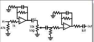
FIGURE 1: A typical high-quality preamplifier.
THE PULL-DOWN T
The pull-down T attenuator is a type of stepped attenuator used to control the overall output of a sound system.
Functionally, it plays the same role as the volume control. Some time ago, using a pair of fairly inefficient loudspeakers and a CD player known for its low output, I found I could bypass the pre-amplifier and plug the CD player directly into the power amplifier without suffering deafeningly loud levels.
The quality improvement-particularly in the treble, detail, depth, and apparent sound stage-was remarkable, but where was the extra quality coming from? What had I removed from the chain that was causing a sound-quality bottleneck-ohm Since the preamplifier's frequency response was already well beyond my hearing range and the op amps I used were transparent, this left only the volume control itself-the potentiometer.
Stepped-attenuator circuits available to hi-fi enthusiasts have been imitation volume controls that you can simply use in place of the volume pot-a straight component substitution. The circuit is not designed around the attenuator and does not utilize its unique advantages. A typical high-quality input stage looks something like Fig. 1. Note the low resistance of the volume control. This is an attempt to reduce the thermal noise that volume controls con tribute, particularly when set to around half volume.
To reduce noise, you must protect the volume pot from any DC in the circuit, but once you put in one capacitor you're compelled to add more. Furthermore, if there is no DC path to ground on the op amp's positive input, it is liable to "latch up" (snap to one of its voltage rails). While most op amps will still function while passing on ±15V DC, and the rest of the circuit is isolated via a capacitor, you can clearly hear a marked fall in quality and increase in distortion. The large-value capacitors required to filter this voltage and maintain frequency response often need to be the electrolytic or bipolar capacitors that you should never place in the signal path of high quality equipment.
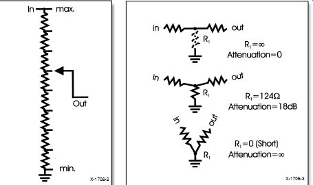
FIGURE 2: Ladder attenuator. FIGURE 3: The pull-down T attenuator.
THE LADDER ATTENUATOR
A regular stepped attenuator looks something like Fig. 2. This is the "lad der" attenuator, where all the resistors are in circuit all of the time. The wiper simply selects various steps on the lad der as if it were a potentiometer, but making the steps right is notoriously difficult, requiring precision resistors.
Figure 3 shows how the pull-down T attenuator works in principle. The input is buffered to two resistors that form the "T," the center of which is pulled down to ground by the attenuator. The output goes to the inverting side of another buffer. This inverting input forms a "virtual earth." The attenuator switches between a real and virtual ground. The pull-down resistor at the center of the T is switched by the attenuator-a different resistor for each step.
At full volume, the pull-down resistor is removed altogether.
Figure 4 shows the pull-down T as it was used in the Ultra Fidelity Concert Sound Systems. The buffer IC also acts as the mixer for the ActiPass crossover. To achieve balance trim, you raise or lower the left-hand side channels by up to 3dB in 1.5dB steps.
This setup ensures no crosstalk from the balance control. An alternative buffer for non-acti-pass systems is also shown.
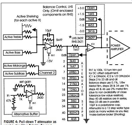
FIGURE 4: Pull-down T attenuator as used in the Ultra Fidelity Concert
Sound System.
With the components shown, the entire attenuator stage has the same specification as the op amps used. Using the Burr-Brown OPA604, you can expect harmonic distortion of 0.0003% and a flat frequency response from DC to more than 400kHz. Note the DC-offset trimpot, a ten-turn type. Once it is set, you never need to touch it. Trimming this resistor prevents "popping" between attenuator steps.
The steps of the Ultra Fidelity Attenuator may seem curious at first. Logically, you might tend to choose 3dB steps, but in practice this is too limiting. The expanded scale used "sounds" more logical; you find that all the steps are useful. At zero attenuation, the amplifier is at maximum for a 1V input.
Note that there is no infinite attenuation-the infinite setting is a waste of a good attenuator step. The highest attenuation is the lowest practical listening level. With the close-tolerance components shown, the steps as marked are within a fraction of a decibel to those tested.
ADDITIONAL DESIGN NOTES
Both balance and attenuator switches are "make-before-break" types. The switch body used for the attenuator has a very stiff action, but you can remove one of the two ball bearings used to make the switch "click" into position.
This design may not be stable when inexpensive op amps are used.
You can solder the resistors directly onto the attenuator in a star-burst fashion, and then connect the ends to form a ring around the attenuator wafer.
The OPA2604 and OPA604 op amps' distortion figures are quoted for a load of 1k-ohm. The pull-down T has a minimum of 2k-ohm.
You can add the active-crossover shelving shown to all the orders--e.g., bass, midrange, treble-that you in tend to use, though it is advisable to leave the shelving off at least one, preferably the midrange in a three-way system, and the bass in a four-way system. The Concert Sound System had the bass shelving set to the overall gain of the system, so that a 1V input would drive the bass speaker to its maximum power handling. There was no accommodation for low-level input signals.
----------------------
Also see: