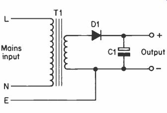
Fig. 1 A simple half wave power supply circuit.
| Home | Audio mag. | Stereo Review mag. | High Fidelity mag. | AE/AA mag. |
Unregulated Supplies
An unregulated mains power supply consists of three basic sections; a transformer to step down the mains voltage to the required level and to provide safety isolation, a rectifier to convert the a.c. output of the transformer to a form of d.c., and a smoothing circuit to change the rough or pulsating d.c. from the rectifier to a reasonably smooth and ripple-free d.c.
The most simple form of power supply is the half wave unregulated type, and this uses the basic arrangement shown in Figure 1. The mains input is applied to the primary winding of the mains transformer, and a low voltage a.c. output is extracted from its secondary. There is no direct connection between the mains supply and the secondary circuit of T1, and it is therefore perfectly safe to come into electrical contact with the secondary circuit of T1, provided, of course, that the transformer has an output voltage that is fairly low. Some transistor circuits, such as power amplifiers, use transformers having secondary voltages of about 40 to 60 volts, and these are capable of inflicting a mild electric shock, but under normal circumstances are not dangerous. The secondary circuit of T1 is connected to the mains earth connection so that if by some means the mains supply should become connected to this side of T1, there will be a large current flow to earth, blowing the mains fuse and cutting off the mains supply. This also reduces the risk of anyone touching the secondary circuit getting a shock to earth of any severity in the brief period before the fuse blows.
Fig. 1 A simple half wave power supply circuit.
The output from T1 is taken by way of rectifier D1, and this is only conductive when the lower connection of T1's secondary is negative, and the upper connection is positive. On opposite half cycles D1 blocks any significant current flow. Thus the a.c. input to D1 has the waveform of Figure 2(a), and the output is d.c., having the waveform of Figure 2(b). This rough or pulsating signal is obviously not suitable to power most electronic circuits. Not only does the supply voltage vary very considerably and rapidly, it is also totally absent for 50% of the time!
(a) The A.C. output from T1.
(b) The output from Dt.
(c) The final smoothed output from the unit.
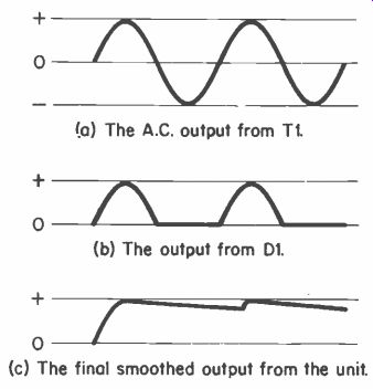
Fig. 2.
This problem is partly overcome by the addition of smoothing capacitor C1. A capacitor has the ability to store an electrical charge, and so on the first positive going half cycles the output rises much as before, charging up C1 to the peak positive output voltage from T1 . Then, as the output voltage from T1 starts to fall away, the charge on C1 provides the output current, and continues to do so until the output voltage from T1 returns to virtually its peak positive value once again.
C1 is then 'topped up' once again, and provides the output current as the voltage from T1 drops away, until the next peak positive pulse from T1. It should be noted that T1 only provides an output and charging current for the brief periods during which the voltage provided by T1 is higher than the charge voltage on C1. For the remainder of the time D1 is reverse biased and does not conduct. This assumes D1 to be a theoretically perfect component with zero forward resistance, which it is not, and it should perhaps be pointed out that for a normal silicon rectifier there will be a forward voltage drop of about 0.5 volts. Therefore, in actual fact D1 only conducts when the voltage from T1 is about 0.5 volts more than the charge voltage on C1, and the output voltage is approximately 0.5 volts less than the peak output voltage from T1.
As C1 cannot have an infinite value, it cannot provide a perfectly smooth d.c. output. There must be some drop in the output voltage during the comparatively long intervals between the charging pulses from T1. This gives an output waveform of Figure 2(c), which is a form of sawtooth waveform. The variation in the output voltage due to the inadequacies of the smoothing circuit is normally called the 'ripple content', or just 'ripple'. What constitutes an acceptable amount of ripple depends very much on the characteristics of the equipment being fed by the supply. Some logic circuits and audio amplifiers are capable of operating from supplies giving ripple levels of several hundred millivolts or even more, since they are designed to have an inherently high level of ripple rejection.
Other circuits will malfunction or give an unacceptably high background level of mains hum if there is even a millivolt or two of ripple on the supply lines.
In general, unregulated supplies are only used where a fait.
amount of ripple can be tolerated, as an excessively large smoothing capacitor would be needed in order to give a really low ripple content on the output, even if only modest currents were to be drawn from the unit.
Full Wave Rectification
In practice it is unusual for a simple half wave circuit such as that shown in Figure 1 to be used, probably because it is rather inefficient. This is due to the mains transformer only providing a brief output pulse once during each cycle, and a transformer having a low secondary impedance is needed in order to give a sufficiently large pulse of current. Another disadvantage of half wave rectification is the relatively long period between charging pulses from the transformer, necessitating the use of a comparatively large smoothing capacitor.
The second of these problems can be overcome by using a full wave circuit of the type shown in Figure 3. This requires a mains transformer having a center tapped secondary winding, or two identical secondaries connected in series to give the same effect. The two halves of the secondary are in effect fed to separate half wave rectifying circuits of the type previously described, with the two outputs being connected together and smoothed by a common smoothing capacitor.
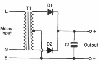
Fig. 3 A simple full wove power supply circuit.
Although this may at first seem to give two half wave circuits connected in parallel, and giving no advantage over a single half wave circuit, this is not in fact the case. The two rectifiers operate in a push-pull arrangement, since when the upper section of the secondary is providing a positive-going signal, the lower one is providing a negative-going one, and vice versa.
Thus, on one half cycle D1 provides the charging pulse to C1.
On the next half cycle D2 provides the charging pulse to C1, and this process continues with D1 and D2 feeding C1 with charging pulses on alternate half cycles.
This type of circuit is no more efficient than a simple half wave type, because although C1 is now charged twice per cycle, and T1 only has to give half the current required by a halfwave circuit during each charging pulse, this is nullified by the fact that either two secondaries or a larger center tapped secondary is required. Thus, where a half wave circuit might use (say) a 12 volt 250 mA transformer, a full wave circuit of this type would need to use a 12-0-12 volt 125 mA component, or one having two 12 volt 125 mA secondaries. In either case the transformer for the full wave circuit has a power rating of 3 watts in total, which is precisely the same as the half wave circuit.
The advantage of this type of rectifier is that it requires a smoothing capacitor of only about half the value of that used in an equivalent half wave circuit for a similar level of smoothing. This is simply because the smoothing capacitor receives a 'topping up' charge twice as frequently in a full wave circuit as it does in a half wave one. The capacitor therefore only has to provide about half as much power between charges in a full wave circuit, and therefore only needs to have about half the value needed in a half wave circuit in order to give the same level of smoothing.
(a) A.C. input.
(b) Output from D1.
(c) Output from D2.
(d) Combined output of D1 and D2.
(e) Smoothed output.
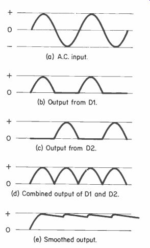
Fig. 4.
Figure 4 shows the output waveforms from various parts of the circuit of Figure 3. Note that w:lereas the frequency of the ripple on the output was the same as the input frequency for the half wave circuit (50 Hz nominal for the U.K. mains), the ripple is at double the input frequency in the case of the full wave circuit. This is not of any great practical significance, although in audio circuits the 50 Hz hum of a half wave supply is slightly less noticeable than the 100 Hz hum of a full wave type. This is more than compensated for by easier smoothing of a full wave supply though, and in practical circuits a half wave supply is not often used, except where high ripple content is not of great importance and only a low output power is required, making efficiency unimportant.
Bridge Rectifier
A bridge rectifier is a lull wave type that does not need a center tapped secondary winding on the mains transformer.
and just needs a single untapped secondary as used for a half wave circuit. Since this single winding provides two charging pulses to the smoothing capacitor per cycle, it is much more efficient than the two forms of rectification considered previously.
Figure 5 shows the basic circuit of a full wave bridge rectifier power supply. As can be seen from this, a bridge rectifier uses a ring of four diodes, and these direct the output of the trans former in such a way as to always give a positive going output signal.
T1 L Mains input Output
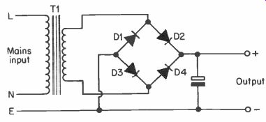
Fig. 5 The basic circuit for a bridge type full wave supply.
As with the other types of rectifier, reversing the diode bridge polarities reverses the output polarity.
For example, when the lower connection of T1 is negative and the upper connection is positive, the output current (using conventional current flow from positive to negative) flows through D2, the load connected across the output, and then D3. When the polarity of the output from T1 is reversed, the current flows through D4, the load connected across the output, and then through D1.
Thus, in effect, the connections to T1 are reversed at the beginning of each half cycle, so that the polarity of the output does not change, and full wave rectification is provided.
Drawbacks
The obvious advantage and attraction of an unregulated supply is its simplicity and attendant low cost, but there are several drawbacks to supplies of this type. One of these is that a high value smoothing capacitor is needed in order to obtain a really well smoothed output. Another is that wide variations in the output voltage can, and in most applications do, occur.
One might think that variations in the mains supply voltage that inevitably occur are primarily responsible for changes in the output potential. However, this is not really the case, although such changes do obviously contribute to some extent to the variations. Since the mains supply is normally much higher than the output voltage of the supply, the voltage step down provided by the mains transformer similarly steps down any variations in the supply voltage at the output of the circuit. For instance, a 12 volt supply will suffer a change in output potential of only 120 mV (0.12 volts) if the mains voltage changes by 2.4 volts. In other words, a 10% change in the 240V mains supply causes a 10% change in the 12 volt output of the supply. Very large changes in the mains supply voltage do not normally occur, and so variations in the input voltage are unlikely to cause any really substantial variation in the output voltage. Certainly not enough to be of any significance with most items of electronic equipment.
Most of the variation in output potential of an un-stabilized supply is due to loading of the supply. There is a certain amount of resistance in the secondary winding of the mains transformer, and through the rectifier circuit. If a current is drawn from the supply, a voltage is developed across the secondary winding, and the voltage drop through the rectifier circuit increases slightly. The total of these voltages is subtracted from the output voltage of the circuit, and can cause an extremely large reduction in output voltage.
If we take a simple example, a mains transformer used in a circuit of the type shown in Figure 3, and having a secondary rating of 12-0-12 volts at 1 amp., would probably give an unloaded output voltage of about 1.5 times its nominal secondary potential, or approximately 18 volts in other words.
Steadily increasing the loading on the output up to 1 amp would cause the output voltage to gradually reduce to some thing in the region of 11 to 13 volts. Reducing the loading from zero to maximum thus gives a drop in the output voltage of about 33 1/3%! Most items of electronic equipment consume a varying amount of current, and when used with an unregulated, supply produce large variations in the supply voltage. This can often produce problems with feedback through the supply lines. Another problem is that an item of equipment such as a class B power amplifier might need a supply voltage of (say) 24 volts at maximum load, but be only able to withstand a maximum supply voltage of about 30 volts without sustaining damage:
This would be a difficult piece of equipment to operate from an un-stabilized supply because a 24 volt transformer having the appropriate secondary current rating would give a satisfactory loaded supply voltage, but would give a supply potential of probably about 35 or 36 volts under quiescent conditions.
This would be far too high to apply to the amplifier. A 20 volt transformer would give a safe quiescent voltage of only about 29 or 30 volts, but the fully loaded supply voltage would only be about 20 volts (assuming the transformer has a current rating equal to the maximum load current). A 20 volt transformer having a secondary current rating of double or more the required maximum output current would give satisfactory results, but with the added expense and bulk of a suitable transformer, one might as well use a stabilized supply.
Another example of where an un-stabilized supply would probably be unsuitable is as a battery eliminator for a transistor radio. Here the problem would be that a transformer giving a suitable fully loaded supply voltage would tend to give a rather high supply potential under quiescent or low load conditions.
While the set would probably not be damaged by the unloaded supply voltage, it would probably result in the mixer and I.F. stages of the set becoming rather lively, giving rise to strong spurious responses or even instability. Again, a trans former having a high secondary current rating could be used, but a stabilized supply would be a more sensible choice.
One other drawback of unstabilized supplies is that the unloaded and loaded supply voltages are rather hard to predict.
In theory, a transformer having a secondary voltage of 12 volts r.m.s., for example, would give a peak output voltage of 1.41 times the r.m.s. output voltage, or just under 17 volts in this case. The final unloaded d.c. output potential would be about 1 volt less than this if a bridge rectifier were used, due to the voltage drop across the rectifiers (assuming silicon devices are used). However, most 12 volt transformers on the market, today actually give an unloaded d.c. output of about 18 volts, some 2 volts higher than one would expect. One 12 volt transformer in the author's spares box was tested and found to give an unloaded d.c. output of some 20 volts, about 25% more than one might expect.
While there are many circuits where wide variations in the supply voltage are of no consequence, and neither is the precise supply potential, this is obviously not always the case. It is therefore necessary to carefully consider the situation before deciding to use an unstabilized supply for an item of equipment.
Choosing Components
It is quite an easy matter to choose the appropriate components for an unstabilized supply of a particular loaded output voltage and current.
If we first consider a circuit of the type shown in Figure 3, the mains transformer should have a voltage rating equal to, or fractionally more than the required loaded d.c. output voltage. Its current rating should be at least as high as the required maximum output current. If the transformer has a current rating which is well in excess of the required maximum output current, the low loading of the transformer will almost certainly result in the output voltage under maximum load being about 10 to 20% more than required. Therefore, apart from considerations of cost and bulk, it is not advisable to use a transformer that has a current rating well in excess of what is really necessary, unless its voltage rating is suitably lowered.
The two rectifiers should have a current rating at least equal to the maximum output current of the supply, and their p.i.v. (peak inverse voltage) rating should be no less than three times the voltage rating of the transformer (which is approximately double the unloaded output voltage of the supply). This may seem to be unnecessarily high at first sight, but it must be remembered that the cathode of each diode connects to the output, and is at the positive supply rail voltage. The anode connection varies from fractionally above the positive rail voltage to a negative voltage of equal amplitude. When the circuit is in the latter state, the cathode of the rectifier is positive by an amount equal to the positive rail voltage, while the anode is negative of the negative supply rail by an almost equal amount. There is thus a reverse voltage of approximately double the supply voltage across the rectifier.
The voltage rating of the smoothing capacitor must be at least 1.5 times the voltage rating of the transformer, and its capacitance value should be at least 1 pf per mA of output current in order to obtain a well smoothed output, and should preferably be several /if per mA of supply current.
A parameter which is sometimes quoted for capacitors, and which is of relevance here, is the maximum ripple current.
Although in theory a capacitor can charge and discharge at a rate only limited by the charging circuit, like any other component, practical capacitors can only handle a finite amount of current. The smoothing capacitor must have a ripple current rating which is at least as high as the maximum output current of the power supply.
Choosing a mains transformer for a power supply incorporating a bridge rectifier is not quite as straightforward as choosing one for a push-pull type circuit. In theory, the maximum current that should be drawn from the transformer when employing a bridge rectifier is 0.62 of the a.c. current rating of the transformer. However, in practice it is quite common for the maximum d.c. output of a power supply to be equal to the current rating of the transformer, as will become apparent when looking at a few practical published designs. In an application where there is to be a continuous and high current consumption from the supply, it would probably be as well to be on the safe side and use a transformer which has a current rating of 1.5 times (or more) the required output current. In applications where a high output current only occurs intermittently, or the equipment is not used for prolonged periods, there are unlikely to be any problems if the current rating of the transformer is equal to or little more than the required maximum output current.
The voltage rating of the mains transformer is chosen in the same way as for the push-pull rectifier circuit. The rectifiers and smoothing capacitors are also selected in the same way.
The use of half wave supplies is not really recommended, except perhaps where very low output current is required, as the low efficiency of these circuits means that the maximum output current available is only a little more than a quarter of the a.c. current rating of the transformer (usually somewhat more in practice). Also, the smoothing capacitor must have a value of double that which would be required in an equivalent full wave circuit.
Rectifier Ratings
The table given below shows the two basic ratings for some popular rectifiers, and should aid the choice of suitable types for readers own power supply designs.
p. i. v.
1 amp max. average forward current
3 amp max. average forward current
50 1N4001 1N5400
100 1N4002 1N5401
200 1N4003 1N5402
400 1N4004 1N5404
600 1N4005 1N5406
800 1N4006 1N5407
1,000 1N4007 1N5408
If we now take a couple of simple examples of choosing components for unregulated supplies: a 12 volt supply having a maximum load current-of 500 mA could use a 12-- 0--- 12 volt mains transformer having a 500 mA secondary curter' rating, together with a push-pull rectifier circuit. The peak inverse voltage across the rectifiers will be about three times the transformer voltage, or approximately 36 volts in other words. In the above table the 1N4001 is the smallest (and cheapest) rectifier capable of handling a p.i.v. of more than 36 volts and an average forward current of over 500 mA, and is the obvious choice. The smoothing capacitor needs a value of about 1µF per mA of output current, and so a 470 uF component is the smallest that is likely to give satisfactory results. If the powered circuit is something like an audio amplifier which is not likely to be tolerant of ripple on the supply lines, a higher value of 1,000 µF or 2,200 µF would be advisable. The unloaded output voltage of the supply is likely to be about 18 volts or so, and so the capacitor must have a voltage rating of at least this figure, a 25 volt type being the lowest suitable voltage rating that is likely to be available in practice. Of course, a high voltage component, such as a 40 volt one, could be used if it is to hand, provided it is not physically too large to fit into the proposed layout.
For our second example, let us assume that a 19 volt supply providing a maximum load current of 240 mA is required, and that a full wave, bridge type rectifier is to be used. It is unlikely that a 19 volt transformer will be available, and so either an 18 or 20 volt type must be used. If the supply is to supply the maximum 240 mA load current for prolonged periods it would probably be better to use an 18 volt type having a secondary current rating of about 400 to 500 mA.
The fact that the transformer is not used at anything like its maximum current rating ensures that it will not be overloaded, and overheating of the component will be avoided. The low loading also helps to compensate for the low voltage rating of the transformer. and the d.c. output voltage should be close to the required 19 volts.
If the supply will only need to supply the full 240 mA output current intermittently, and 18 volt 250 mA transformer (or a 9 0-9 volt 250 mA type with the center tap ignored) should give satisfactory results, although the d.c. output voltage might be fractionally low at maximum loading. A 20 volt 250 mA type should also be suitable, although in this case the output potential will be slightly higher than required. However, both types should give results of adequate accuracy since an unstabilized supply is not suitable for applications where the supply voltage is critical.
The rectifiers must withstand a peak inverse voltage of about 54 (18 x 3) or 60 (20 x 3) volts, at a maximum average current of 240 mA, and so four 1N4002 types would be suitable. The smoothing capacitor requires a value of about 240 AF, 220µF being the nearest preferred value to this. For applications where a really well smoothed supply is needed a 470 µF or 1,000µF component should be used. The capacitor a maximum voltage of about 27 (18 x 1.5) or 30 (20 x 1.5) volts, and 40 volts is the lowest suitable working voltage in which capacitors are commonly available.
Series-Parallel Transformers
There are a number of transformers available these days which have twin secondaries of identical voltage and current ratings.
These are designed so that they can be used with the windings connected in series or in parallel. For example, a transformer having two 12 volt 500 mA secondary windings can be connected as shown in Figure 6(a) in order to give a 24 volt 500 mA output. This is the series mode. By using the junction of the two windings, the component can be used as a 12-0-12 volt 500 mA type, as shown in Figure 6(b).
With the windings connected in parallel, as shown in Figure 6(c), the transformer is effectively a 12 volt 1 amp type. In other words, series operation gives double the output voltage of a single winding, and parallel operation gives twice the output current of a single winding. When using the parallel mode it is necessary to make quite sure that the windings are connected correctly, since a very high current will flow if the connections to one of them is reversed, causing the component to quickly burn out.
Mains in
(a) Connecting twin secondaries in series.
Mains in 0V Output 12V
(b) Method of connecting twin secondaries to feed a push-pull rectifier.
12V Mains out in 120V
(c) Connecting twin secondaries in parallel.
(d) Connecting twin primaries for use on 240V U.K. mains.
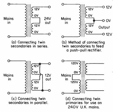
Fig. 6.
For the same reason it is also important that the parallel mode should only be used if the manufacturers or retailers literature states that the two secondary windings are accurately matched, and can be safely used in the parallel mode. With types not specifically designed for parallel operation there is a real risk that there will be a small but significant difference in the two secondary voltages. This would result in one winding forcing a fairly heavy current through the other winding, causing the component to eventually overheat and be destroyed.
Of course, it is not essential to use both windings of a trans former, and if one winding is capable of supplying the required current, the other one can simply be ignored.
It is perhaps worth mentioning here that some of the trans formers available these days have two 120 volt primary windings. These can be connected in parallel for use on the 120 volt (or thereabouts) mains supply found in many countries, or in series for use on the 240 volt U.K. mains supply (see Figure 6(d)).
Improved Smoothing
The smoothing of a simple power supply can be improved considerably by using two smoothing capacitors together with a resistor or choke, as shown in Figures 7(a) and 7(b) respectively. One problem with this method is that there is inevitably a voltage drop across the resistor or choke, necessitating the use of a higher voltage transformer. In the case of the choke, there are the added disadvantages of the rather high cost and large size of a suitable component. This type of smoothing circuit is not often used these days because it is probably better to use a simple stabilized circuit (which provides electronic smoothing).
Fusing
Although mains plugs containing fuses are in common use these days, the lowest current rating commonly available for these plugs is 3 amps. This is far higher than the current consumption of most items of electronic equipment, and affords little protection. It may therefore be worthwhile adding a fuse in the 'live' mains lead to the mains transformer.
(a) A power supply using C-R smoothing.
(b) A power supply using choke smoothing.
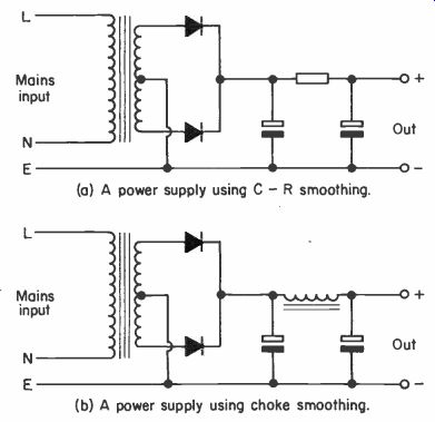
Fig. 7.
For reasons of safety it is advisable to fit it in a panel mounting fuseholder, and not a chassis mounting type (where there would be a strong risk of an electric shock being sustained if the fuse was to be changed while the equipment was still plugged into the mains).
In order to find the current rating for the fuse, first multiply the secondary current taken from the transformer by its secondary voltage, so as to determine the power drawn from it. For instance, if 250 mA is drawn from a 12 volt trans former, the maximum power taken from the supply is 12V x 0.25A = 3 watts. If 2 amps current is drawn from a 20-0-20 volt transformer, the output power is 20V x 2A = 40 watts.
If the transformer has more than one secondary, the output powers of the secondaries must be added together to derive the total power drawn from the transformer. The total output power in watts is then divided by the mains voltage (240V in the U.K.) to give the primary current. Thus, in our two examples above, the primary currents are 12.5 mA and 166 mA respectively. To allow for losses through the transformer a further 50% should be added, giving 18 mA and 250 mA in the above examples. A 100 mA fuse would probably have to be used in the first case, since this is the lowest fuse rating that is generally available. In the second case a 250 mA fuse can be used, as this is a rating in which fuses arc readily available. If the calculated rating does not coincide with one that is available, always choose the nearest rating that is higher than the calculated one.
A fuse can also be added in one output lead from the secondary of the transformer, and will protect the transformer in the event of a smoothing capacitor going short circuit, a fault in the rectifier circuitry, or a general overload on the supply. In the case of a transformer feeding a push-pull type rectifier, the fuse is connected in series with the lead from the center tap on the secondary (i.e. the 0V connection). The fuse has a rating which is equal to the maximum output current that will be drawn from the supply, or the lowest rating above this figure if a fuse of the appropriate rating is not available.
It may be necessary to use an anti-surge fuse, particularly if a very large smoothing capacitor is used, as the initial and high charge current taken by the smoothing capacitor at switch-on can often be sufficient to activate 'quick blow' type fuses.