When the cone of a moving coil speaker moves backwards and forwards it generates two separate sound waves, one at the front and the other at the back. Air is compressed in one direction while that in the other is rarefied. The two waves are thus said to be out of phase.
Phase is often described by comparing it with an imaginary line rotating round a central point, a device termed a vector.
At a half-revolution which is 180°, the signals are displaced by one half-cycle, and are totally out of phase. At 90°, the signals are a quarter-cycle displaced and are said to be in quadrature.
Two out-of-phase signals can be represented by two lines drawn one from the end of the other at the appropriate angle, and if they are drawn to scale with the length representing signal amplitude, the value of the resulting signal (the resultant) can be found. This is done by simply joining the end of the second to the start of the first by a third line to form a triangle. The length of the third line then gives the amplitude of the resultant (Fig. 13).
It is useful to be familiar with these concepts as they frequently appear in technical discussions where out-of-phase signals are involved, such as with loudspeaker systems.
Such a case is a loudspeaker generating two 180° out-of phase signals at its front and rear. When these meet at the rim of the speaker, the compression regions merge and fill the rarefaction zones so little sound is actually radiated. Of that which is, only high frequencies having a wavelength shorter than the radius of the cone remain, as one or more complete cycles of these are propagated before cancellation occurs at the rim. This accounts for the familiar tinny effect when a loudspeaker is operated without a baffle.
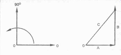
Fig. 13. Vectors. Signal amplitudes are indicated by line lengths and
phase by angles. During a complete cycle, line rotates through 360°. If
two signals A and B are drawn one from the end of the other, the phase
angle and amplitude of the resultant is determined by a joining line C.
It is evident then that some means must be provided to keep the two out of phase waves physically apart; this is the sole purpose of the speaker cabinet or enclosure as it is now more usually called. As we shall see there is a lot more involved in this than at first may appear. Much ingenuity has gone into the design of these boxes,-boxing clever in fact. But every known method has disadvantages so it is a case of choosing which set of disadvantages are least objectionable. We will explore the various methods in common use, size up their good and bad points, then we can make an informed choice or perhaps even design our own.
In passing it may be noted that the ideal reproducer would be a pulsating sphere rather than a backward-and-forward moving cone. This would radiate in-phase sound in all directions and so eliminate all the problems associated with the disposal of the rear wave. Many attempts have been made to achieve such a device but none so far successful. The nearest has been the plasma speaker described in the last section, but this covers only the high frequencies whereas it is the bass that presents the problems.
Baffle/Doublet
An obvious way to keep the waves apart is to mount the speaker on a large flat board which is termed a baffle. They still meet at the edge, but they have further to go and so longer wavelengths can be propagated before cancellation takes place. Thus the bass response is extended compared to that of an unmounted speaker (Fig. 14). The straightforward baffle has many advantages, among which is the lack of air resonance that produces the coloration inherent with an enclosure. Also panel resonances and vibrations common with cabinets are minimal.
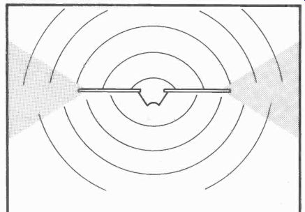
Fig. 14. Flat baffle. Extends front/back path via which out-of-phase
sound waves merge and cancel, thus lowering frequency at which cancellation
occurs.
One potential snag is that because of the time taken for the rear sound waves to reach the edge of the baffle, delays occur which at some frequencies can mean that a compression wave from the rear is propagated at the same time as the next compression wave from the front, so that they actually reinforce each other. At other frequencies the opposite occurs and cancellation takes place. Reinforcement occurs at wavelengths that are 0.5, 1.5, 2.5 ... times the radius of the baffle, whereas cancellation takes place at whole multiples, 1.0, 2.0, 3.0 . .. times the radius.
The net effect of this is a very uneven frequency response with alternate peaks and troughs throughout its range. It can be easily avoided by simply mounting the speaker off center on the baffle. There is thus no uniform radius and the cancellation and reinforcement effects are smoothed out. A rectangular baffle with the speaker off center gives good results, but a circular or square one with the speaker at the center is the worst possible case (Fig. 15).
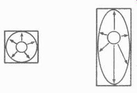
Fig. 15. A speaker in the center of a square baffle has an almost equal
radius to the baffle edge so cancellation occurs at whole multiples of
the radius wavelength and reinforcement at half multiples.
This effect is avoided in a rectangular baffle where the radius is not the same in all directions thus smoothing out interference effects.
The big problem with an open baffle lies in the size of baffle needed to procure an adequate bass response. To achieve a flat response down to 45 Hz, requires a baffle with the shortest radius of 25 ft (7.7 m). That means a width and height of more than 50 ft, which is obviously impossible for domestic use, and most other uses too!
Looking at more practical dimensions, a 2ft radius which is a 4 ft width or height would be about the maximum, especially as two are needed for stereo. This would start to roll off at 280 Hz which is inadequate for hi-fi, but an ameliorating factor is that the bass fall-off is only 6 dB per octave. This means a- 6dB response at 140 Hz, and a -12 dB level at 70 Hz. The bass response of most enclosures drop sharply below their rated limit, so with a baffle of this size there is at least some response in the bass though not very much. A further factor is that the reproduction sounds more natural and musical when the fall-off is gradual than when it is abrupt.
Doublet
Propagation pattern from an open baffle is that of a doublet or figure-eight configuration, with roughly equal radiation from the front and from the rear. The sound pressure at any off-axis angle is equal to the cosine of the angle times the on-axis pressure. Or to put it mathematically:
p = cos0P
... in which p is the off-axis sound pressure, 0 is the angle, and P the on-axis pressure.
At high frequencies the angle narrows and off-axis levels are lower due to cancellation from different regions across the width of the speaker cone. Also there are irregularities in the rear response caused by reflections from the speaker chassis and magnet assembly.
Because of the strong rear propagation, an open baffle should be operated well clear of a backing wall otherwise reflections from it will reinforce and cancel quarter and half wavelengths and their multiples, of the spacing between the baffle and the wall. Modification of the doublet radiation pattern can be obtained by mounting two baffle speakers in a V configuration.
Adding Sides
The dimensions of a baffle can be increased by adding sides, a top and a bottom. If these are narrow compared to the total width of the baffle there will be little adverse effect and the front-to-back path is extended thereby slightly improving the bass response. Increasing the width of the sides further extends the bass, but at the expense of a degree of coloration due to resonance of the air in the structure which behaves as a short pipe. However, as the width of the 'pipe' is large compared to its length, the effect is not great.
A further step is to add a back in which a number of slots have been cut. This adds to the front-to-back path and the slots serve as an acoustic resistance to the rear wave. So the bass is noticeably increased. However, the enclosed space has a more pronounced resonance which affects the reproduction.
The back itself could resonate, being of a large unbraced area, unless it was of substantial thickness and screwed at frequent intervals around its perimeter.
Really, we now have a conventional loudspeaker cabinet such as used for medium quality audio systems. The bass is still deficient compared to that of a well-designed enclosure, but the reproduction is likely to be less colored and more natural than many so-called hi-fi units.
Such a cabinet can give very satisfactory results if robustly constructed and made large enough to give a reasonable bass response. Dimensions are not critical but it is best to make the front as large as practicable, and the sides not too deep. The speaker should be off center, but it need not be off center relative to the width, the condition is satisfied if it is mounted toward the top half of the cabinet. If it is too far off center the shortest path from front-to-back is reduced and with it the bass response.
A practical shape to take account of the above condition is to make the cabinet much taller than it is wide. Most listening rooms have floor space limitations but no reasonable limit as to height. The short path from the speaker unit to the top edge can then be made larger than the paths from the speaker to the sides. It should not be equal to them. Bass response is then dependant on the width.
An interesting possibility for extending the width of either a flat baffle or a cabinet is the use of folding doors. A pair of doors are hinged at the sides of the baffle or cabinet, so that they either close in front or are pushed back against the sides.
When open, they form wings or extensions to increase the width, but are closed when not in use to save space (Fig. 16). Fig. 16. Extending doors can increase the front-to-back with an open-backed cabinet of modest width.
As each door can be half the width of the baffle, the two effectively double its width. There may be insufficient room to accommodate such a width even temporarily during listening sessions in which case the doors can be made narrower. They would then look rather odd when closed over the front as they wouldn't meet, so it might be better to have narrow doors folding back. The hinges should be full length piano hinges to eliminate air gaps between door and baffle, and if possible some means of locking the doors firmly open is desirable.
Coloration, though comparatively small could be reduced further by making the cabinet an irregular shape if one's woodworking skills are up to it. An irregular pentagon or hexagon are possibilities, or perhaps more simply a quadrangle with non-parallel sides. Ideally the speaker should be mounted in the widest portion to maintain a long minimum front-to-back path. If this is at the top though, care would be needed to ensure stability.
Whatever mode of construction is considered, size will always be the main obstacle to obtaining good results from a baffle or simple cabinet. This is compounded by the strong rear wave which means that the speakers must be placed well away from any wall and thus take up even more room. For this reason, and especially in view of limited space in modern living accommodation, coupled with the desire for high quality sound reproduction, other means are employed to dispose of the rear wave. These generally offer a good bass response with moderate size, but as may be expected, there are penalties.
Infinite Baffle
An obvious and seemingly simple way of keeping the front and the rear wave apart is to mount the speaker in a sealed air-tight box so that the rear wave is totally confined to it. It is the method most commonly used for hi-fi speakers as it achieves an extended bass response with moderate and in some cases quite small size.
As the baffle has no edges around which the two waves can merge it has been dubbed infinite baffle, but as the size of the box is by no means infinite it is really a misnomer. The bass driver used for this type of enclosure requires a weaker or more compliant suspension than other types because the springiness of the trapped air restrains the cone movement and therefore itself serves as a suspension. The driver and the enclosure is therefore often described as of the acoustic suspension type.
An important restriction must be observed with these drivers. They should never be used in ordinary unsealed cabinets. Without the cushion of air behind the cone, the mechanical suspension is too weak to hold it in place by itself, and damage would soon result.
The big snag with this principle is that the air cushion can considerably modify the motion of the cone, and so distort the front sound wave radiated from it. We saw in the first section that the resonant frequency of a bass driver should be as low as possible, because the response falls off rapidly at the rate of 12 dB per octave below it.
The dampening effect of the trapped air on the cone decreases compliance and results in a raising of its resonant frequency. The larger the box, the greater the volume of air it encloses, the larger its compliance and the smaller its dampening effect. This is so because a given cone excursion exercises less compression on a large air volume than on a small volume. Hence our first rule for infinite baffle enclosures is: with a given driver a large box has a lower resonant frequency than a small one.
Using the same logic, a small cone compresses a given air volume less than a large cone. So the cone size also influences the enclosure resonant frequency, so our second rule is: a small cone produces a lower enclosure resonant frequency than a large one. However, because of its smaller mass it had a higher free-air resonance to start with.
Putting all this together, three things affect the resonant frequency of the enclosure, 1) air volume, hence box size; 2) cone size; and 3) cone mass. As we saw in section 1, the compliance of the cone surround also affects the resonant frequency, but with this type of driver the surround compliance is a minor factor compared to that of the air in the box.
A desired resonant frequency can thus be obtained by selection of these three factors. If one or two are immutable, then the required result can be achieved by selecting the other.
The accompanying chart shows the relationships and enables a selection to be made (Fig. 17).
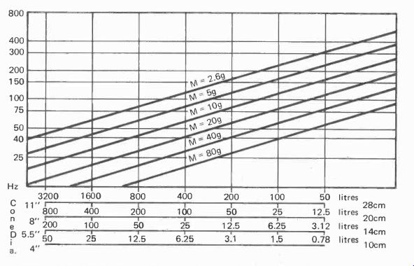
Fig. 17. Resonant frequency from enclosure volume, cone diameter and
cone mass.
Damping and Q
At the enclosure resonant frequency, the cone excursion is larger than at all other frequencies, hence the sound output is greater, and a peak appears in the frequency response. If undamped, this results in a boomy sounding bass, one note predominates, in fact the effect has been dubbed 'one-note bass' The magnification of cone movement at resonance compared to that at other frequencies is denoted by the letter Q. Students of electronics will recognize that this is the term applied to an inductor to denote its reactance divided by its resistance. A high Q means the coil will tune sharply with a large peak and so it is rated as a quality factor, hence the designation.
In the case of a loudspeaker, the same term is used to describe a like magnification at a resonant frequency, but here Q is rather a misnomer as the result is the opposite of quality.
When a loudspeaker cone is impelled backwards and forwards by the applied electrical signal, the coil windings are cutting through the magnetic field and so a voltage is generated in them. This voltage is of opposite polarity to the applied voltage, hence it is termed back emf. This voltage produces a back current which flows through the coil and through the output circuits of the amplifier. Although the output impedance of most amplifiers are rated at around 4-8 ohm, this is a nominal figure to which the total loudspeaker impedance should be matched for efficient and safe operation. The actual resistance offered to a current flowing in the output circuits is very much lower, a fraction of an ohm in most cases.
Compared to the resistance of the coil, the amplifier output resistance is negligible, so the back current is limited mainly by the coil resistance. The current sets up a magnetic field around the coil which exerts a force that opposes the original motion.
Now this opposing force is not proportional to the applied signal, but to the original cone motion which generated it. So, an excessive cone motion at any one frequency produces a larger opposing force at that frequency. It can be seen from this then, that the opposing force is greater at any peak resulting from a resonance, and thereby the Q is reduced and the peak is dampened.
The degree of dampening depends on the magnitude of the opposing force, which in turn depends on the efficiency of the system as a generator. Generator efficiency is governed by the magnetic flux density and the length of the coil, and inversely by the coil resistance, the cone inertia which depends on its mass, and the frequency of resonance.
There are thus mechanical factors and electrical ones that make up the total Q of the system. These are designated as Qms and Qes in maker's specifications. They are combined in the following formula to describe the total Q of a driver, Qts:
Qms X Qes Qts =
Qms + Qes 1 1 1 or + Qts Qms Qes
The total Q designated Qts, is that of the driver only. The total including the cabinet is described as Qte. This of course cannot be specified by a manufacturer because he does not know the size of the cabinet in which the driver will be used, but it does appear in formula which we can use to determine the optimum cabinet size as we shall see.
If Qt, is equal to unity, there is no peak at the resonant frequency because the amplitude of the cone excursion is just 1 times that at any other frequency. This would appear to be the ideal value. However, an undamped response consists of a peak that is sharp at its tip while being fairly broad at its base.
If now we level the tip to unity value, there is still a slight rise on either side due to the 'foothills' of the base. The lower one disappears due to the bass roll off below resonance, but the upper one remains.
A Qt, of unity therefore produces a small rise just above the resonant frequency. The chart shows the effect (Fig. 18).
To eliminate this, we need a Qte that is actually less than unity.
This is possible by reducing the cone diameter, or for a given driver, increasing the volume of air in the enclosure, which means increasing its size.
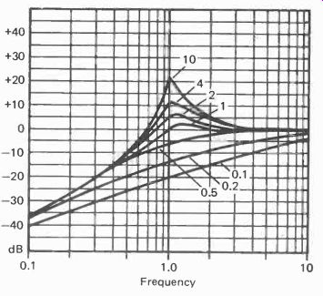
Fig. 18. Response at resonant frequency for different values of Q.
The optimum value to obtain a smooth response is 0.7. although this causes a bass roll off slightly higher than the resonant frequency. If the resonant frequency can be made low by having a large enclosure, the small sacrifice in bass is worth it in order to get a smooth and more natural response. With small enclosures a Q of unity may be necessary to extend the bass as far as possible which means to the resonant frequency.
The slight rise just above it further emphasizes the bass and gives the impression of a good bass response, although it is at the expense of naturalness and will give a somewhat boomy result.
Enclosure Size
The formula for designing a sealed enclosure for a particular driver, is quite a complex one, but it can be greatly simplified if its use is restricted to a Qt, of 0.7. For other values it is less accurate. The governing factors are: the compliance of the drive unit's suspension; the volume of air having the same compliance; the mechanical Q, Qms; and the electrical Q, Qes To simplify matters further, these four factors are combined into two in the Thiele-Small parameters quoted in maker's specifications. The volume of a body of air having the same compliance as the suspension of the driver unit is given in liters and denoted by the term Vas. The mechanical and electrical Q are usually combined according to the previous formula and given as Qts.
So we need only the Vas and the Qts. The formula is:
as Qtc is 0.7, then Vb =
Qtc2 Qts2 Vb =
Vas x Qts2 Vas X Qts2
0.49- Qts2
Not all bass drivers have the high compliance required for use in sealed enclosures, many are designed for open-backed systems. If this formula is used for those, it will produce a cabinet volume of impractical size.
The volume is of course of air, so it is the internal dimensions that we must use for calculation, and any internal solids must be deducted. The principal one would be the bass driver itself. The volume of this can be approximately calculated by regarding it as a cone. To find the volume of a cone we multiply the area of the base (the speaker cone) by the height (distance from the front of the unit to the back of the magnet) and divide the result by three. Area of the base is given by nr2. To express all this as a formula we have:
irr2h V- 3
In which V is the volume, r is the radius of the speaker, and h is the height.
The tweeter should be calculated the same way. Structural bracing and cross-over units should be allowed for, as should also dense absorbents such as bitumous pads. These items are of greater importance in small enclosures in which they take up a larger proportion of the air space than in larger ones.
Loose absorbent such as BAF wadding actually increases the apparent enclosure volume for a reason we shall explore in a later section. Sufficient here to say that the internal air volume can be reduced by about 5% when wadding is used to fill the enclosure.
Sensitivity
The amount of acoustic output from a given electric input is what is meant by the term sensitivity, not the way the speaker responds to transient or other types of signal unless that is specifically stated. For the infinite baffle speaker the sensitivity is low. The reason is not hard to understand. In order achieve a low resonant frequency and thereby obtain an extended bass response without a very large enclosure, the mass of the bass driver is made large. Mass requires power to move it, so more power is needed to do so than for a driver with a lighter cone.
Efficiency, hence sensitivity could be increased by making the magnet stronger, but as we have seen from the Q formula, this reduces the Q and results in overdamping. In turn, overdamping eliminates the effect of resonance on the bass response and results in the bass roll-off starting at a much higher frequency.
The rather unexpected result is that many small speakers need a higher amplifier power to obtain sufficient sound output than larger ones, simply because they are made less efficient in order to get a better bass response.
Dimensional Resonances
In addition to the main air/cone resonance we have discussed, there are air resonances that are functions of the three enclosure dimensions. These resonances occur when the dimension is equal to half a wavelength, and if undamped will cause coloration of the reproduced sound at the corresponding frequencies.
The first thing to ensure is that none of the dimensions are the same. Height width and depth must all be different. This applies also to multiples of those dimensions so that one should not be a half, third or a quarter the size of another. To avoid similar problems in listening rooms, what is known as the golden ratio is often invoked. This is to make the dimensions of the room comply with the ratio 1 : 1.6 : 2.5.
Any of these can be multiples or sub-multiples such as 1 : 3.2 : 2.5.
The same rule can be applied to infinite baffle enclosures in order to spread the resonances and avoid any coinciding.
Should this happen, there would be a very pronounced peak at the frequency corresponding to the half-wavelength. Even worse would be a square box or a rectangle having the same width and depth with the height double the width. That would cause a very strong resonance and severe coloration.
As with the unsealed cabinet, an irregular shape with non-parallel sides reduces dimensional resonance effects. The ultimate shape for doing this is a pyramid, and at least one commercial speaker has been made in this form. The disadvantage apart from the woodworking problems, is that a pyramid has only a third of the volume of a rectangle of the same base area and height. So, either the base and/or height must be increased to compensate, or the reduced bass response inherent with a smaller enclosure must be accepted. As speakers are expected to be compact and have a good bass response, it can be appreciated why the pyramid has not caught on commercially.
When a resonance is excited between two parallel surfaces such as the sides, top and bottom or front and back of an enclosure, what are called standing waves are set up. As the half cycles of the waves travelling back and forth are exactly the same length as the space between the surfaces, the respective areas of high and low compression always appear in the same place and so the wave seems to be standing still. The points of minimum vibration are termed the nodes, while those of maximum motion are called the antinodes.
At the fundamental resonance frequency the antinodes appear halfway between the surfaces, which is at the middle of the enclosure. However, each frequency is accompanied by a number of harmonics, that is further frequencies at double, treble, four times etc, the frequency of the fundamental. These also have a pattern of nodes and antinodes.
The second harmonic has antinodes at one-third and two-thirds of the dimension; the third harmonic antinodes are at one-sixth, a half, and five-sixths the length. Antinodes of the fourth harmonic appear at one-eighth, three-eighths, five-eighths and seven-eighths, and so on.
Dimensional resonances can be dampened by the placing of absorbent material at the antinode positions where the vibrational motion is greatest. It has virtually no effect at the nodes. From the above it is evident that the nodes of the fundamental and all the harmonics are at the surfaces themselves, so material fixed to the cabinet walls have no effect on these resonances. As there are many antinodes of the fundamental and the harmonics spaced across the dimension, and there are further ones from the other two dimensions in the same space, it follows that to be effective, damping material should fill the whole enclosure.
This is done in most of the small enclosures with thick rolled-up layers occupying most of the space. The material used is of a cellular form, so air is present throughout, but the passage of sound pressure waves is impeded. The presence of this material also slightly increases the effective volume of the enclosure because of its slowing down effect on the sound waves passing through it. They thus take longer to reach the boundary wall just as if the dimension was longer and the wall was further away.
With large enclosures there are practical difficulties in completely filling the volume with absorbent. The problem is that the weight causes the material to compact at the bottom and leave gaps at the top. It should not be compressed too much as this forces out the air and so effectively reduces the internal air volume of the enclosure. One solution to this is to fix several 'shelves' of nylon netting (not wire which could vibrate) across the cabinet to support the layers of absorbent.
Panel Resonance
There is yet a further type of resonance which can color the reproduction from a sealed box type of speaker. The fact that the box is sealed and no air can escape produces large pressure differences between the inside surfaces and the external ones which are at the normal atmospheric pressure.
These differences cause the walls of the enclosure to vibrate in and out in sympathy with the pressure differences. They thus produce sound, but because they also have particular resonant frequencies and their motion is not in linear proportion to the pressure, the sound they radiate is highly colored.
So it is necessary to reduce panel vibrations to the minimum and many different materials and types of construction have been tried with this end in view. One of the best is brick or concrete which has a high density and so a high resistance to lateral vibration. The practical problems are fairly obvious, although with the popular mode of decor for raw brick interior walls and fireplaces, a pair of brick speaker enclosures could match the rest and so not be aesthetically displeasing. With any such projects, the ability of the floor joists to support the result must prudently be considered.
A very effective alternative is sand-filled panels. Each panel is constructed of two sheets of wood separated by square section moulding around three edges, then sand is poured into the space between them. The fourth edge is finally sealed with a length of moulding. The panels must be made to the correct size as they obviously cannot be cut afterward (Fig. 19).
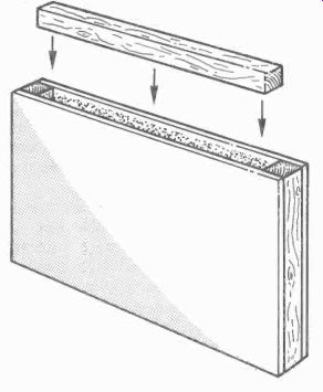
Fig. 19. Sand-filled panel. Two wooden sheets are assembled with square-section
along three sides. The cavity is filled with sand and the fourth square-section
fitted. Seal all joints to prevent sand leakage.
Perhaps the most common material used is 11 or # inch plywood, but it is very prone to vibrate by itself without bracing or damping. To improve matters, many designs employ cross-bracing to improve rigidity. While it does this to a certain extent it is not all that effective in reducing vibrations.
The trick is to fit the bracing at the points where the maximum amplitude of vibration occurs, the antinodes. One way of doing this experimentally requires the use of an audio oscillator. The cabinet with drivers in place is temporarily sealed with its back and laid so that the panel under test is uppermost. An amplifier is connected and the oscillator output applied to its input.
Powdered chalk is scattered evenly over the panel, and the amplifier turned well up. The frequency of the oscillator is varied over the low to mid frequency range until the chalk settles in a discernable pattern. The regions where there is no chalk are those of maximum vibration and are the ones that need bracing.
Struts and battens reinforce one point only whereas the vibration nearly always occurs over a larger area. A better method is to use a partition along the affected region. It should have plenty of large holes drilled in it to allow the free passage of sound pressure waves through.
Plywood is available in many thicknesses and grades. The number of plys vary from 3 to 19, but they are always an odd number to inhibit warping. Grades range from type A, which is guaranteed free from surfaces defects to WG which is very rough and normally used for packing cases. Type B/BB is preferred for speaker cabinets because one side is first grade, but the other may have plugs. These are inserts glued in to replace knot holes. This side of course goes inside the enclosure.
Another form of plywood is blockboard, in which a number of rough blocks are sandwiched between two facing sheets, and laminboard which is similar but contains a larger number of smaller blocks. The latter has better damping properties than conventional plywood, but the edges have to be disguised with veneer unless all outside joints are mitred.
Chipboard is another much favored material. It is made by compressing resin coated wooden chips between steel plates.
Here too there are numerous grades. Single layer chipboard consists of chips of the same size throughout and so has a consistent density. Three-layer chipboard has two outer layers of high density to give a better surface finish with a lower density interior. The multi-layer grade has two outer high density layers and also a high density core with lower density in between. There is also a graded density chipboard in which the density varies gradually throughout its thickness (Fig. 20).
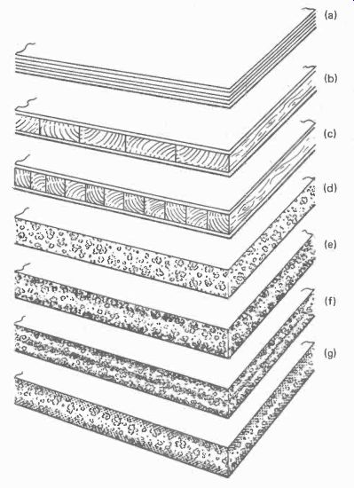
Fig. 20.
(a) Plywood (b) Blockboard (c) Laminboard (d) Chipboard single-layer (e) Chipboard three-layer (1) Chipboard multi-layer (g) Chipboard graded density
The densities are rated by weight and range from 400 to 900 kg/m^3 although some cement loaded grades go up to 1150 kg/m^3. The best for speaker enclosures is a single layer high density type of at least 600 kg/m^3. This is especially so for the front panel where rebated holes may have to be cut for the drivers. Alternatively plywood could be used here. Chipboard is available veneered on one side which solves the finishing problem providing the edges are rebated with care.
Another material gaining in popularity is fiberboard. In this the wood is reduced to fibers which are felted and pressed into sheets with little or no extra resin being added. The bond arises from the felting and the natural adhesion between the fibers.
The sheets are tempered into hard boards by impregnation with hot oil or sometimes resin and then heat-cured.
The density of fiberboard is higher than chipboard ranging from 800 to 200 kg/m^3, and it also has frictional losses between the fibers which increase its damping factor. It has a smooth finish on one side, and a grainy one on the other.
Thickness is limited at present to +inch, but medium density fiberboard (MDF) from 640 to 860 kg/m3 is now available up to 1+inch thicknesses.
When plywood is used is has been found that lining with builders plaster board has a better effect and is superior to the same thickness of plywood. So a finch, sheet of plywood bonded to a finch sheet of plaster board is better than a finch sheet of plywood. Remember to allow for this or any other damping material fixed to the inside surface of the cabinet when working out the dimensions. It is the inside dimensions that matter.
For small to medium sized enclosures, a rather surprising discovery is that thinner wood is best, providing it is lined inside with thick bitumous pads. Suitable pads are available from specialist mail-order loudspeaker dealers such as Wilmslow Audio. This arrangement seems to be one of the most effective methods of reducing panel resonances in wooden enclosures. So although damping material fixed to the inside surface of the enclosure has no effect on the internal dimensional air resonances, it is essential to deal with the panel resonances.
For most of the panels, the damping need not extend over the whole inside surface as long as it covers at least 60% of the central area. It may be easier for calculating the internal air volume though if it does in fact extend to the edges. The back panel should be fully covered for the following reason.
Reflected Wave
While the rear pressure wave generated by the back of the speaker cone fills the whole enclosure and affects all parts of it, its principal impact is against the rear wall of the enclosure where it is reinforced by direct air particle velocity. A strong wave is therefore reflected back to the loudspeaker. Now paper is transparent to sound waves of mid and lower frequencies as can be proved by taping a sheet of paper over the front of a loudspeaker, the sound is heard at almost undiminished volume. So, when the reflected wave reaches the paper cone of the loudspeaker, it passes straight through it to emerge at the front (Fig. 21).
However, it is delayed compared to the original, by the amount of time it took to travel to and from the rear enclosure wall. When the depth of the enclosure is equal to a quarter or three-quarters of a wavelength, the reflected wave reinforces the original, but when the dimension is a half or a whole wavelength or a multiple, the wave cancels it. Thus we get a series of peaks and troughs in the frequency response corresponding to those frequencies that are reinforced and cancelled.
Sometimes an audible 'honk' is produced by the interaction of the reflected wave with the next cone excursion. To reduce the reflected wave to a minimum, the rear wall must be heavily damped with absorbents or damping pads, it being of greater importance here than anywhere else.
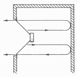
Fig. 21. Pressure wave from rear of the speaker cone is reflected from
rear wall of the enclosure and passes right through the cone to emerge
delayed and so out of phase with the original.
Considerations
It can be seen from all this then, that producing an infinite baffle speaker is no means a case of simply mounting a driver or two in a sealed box, although that is how some speaker manufacturers appear to view it. Many parameters have to be considered in order to get the design right and even then reputable makers often have to make many trial-and-error modifications to the prototype before the speaker is released on to the market.
Generally, the smaller the speaker the tighter are the tolerances and the greater the effect of small errors. A real problem is the decision to opt for either an apparently extended bass or a smooth bass, then design for the required Q. The difficulties in subduing the dimensional and panel resonances inherent with sealing up a hefty sound pressure wave in an airtight box also must be met; rather like sealing a genie in a bottle! If all these problems are successfully tackled, good results can be obtained.
There is though one remaining inherent disadvantage with the airtight enclosure for which there is no real solution. It can best be understood by comparison with a bicycle pump. If you slide the extended handle of a bicycle pump inward with the exit hole free, what little resistance it meets is the same along its whole travel. If now you do the same with a finger pressed over the exit hole, the resistance though slight to start with gets progressively greater until it is virtually impossible to push. the handle the last few inches. The reason is because the internal air pressure increases with the inward travel of the handle.
A similar principle applies to a loudspeaker cone working against the air in a sealed box; there is little resistance to the initial cone movement, but as the cone travels further inward, the internal pressure rises and offers an increasing back pressure. According to Newton's Laws of Motion, the movement of a body is the result of all the forces acting upon it. So, the cone excursion is progressively reduced the further it travels. Its motion is not solely dependant on the applied signal as it is with a speaker on an open baffle. There is a similar effect when the cone moves outward, but now it is creating an increasing vacuum as it does, so its outward excursion is likewise inhibited (Fig. 22).
The result is a non-linear response to the applied signal.
However, at mid and high frequencies, the cone has completed its excursion and is moving in the opposite direction before the pressure has had time to build up and exert a back force. So at these frequencies, there is little audible effect, but at lower ones that are in the bass register, non-linear back pressure causes high harmonic distortion. The larger the cabinet the lower the frequency at which non-linear back pressure starts having an effect, so small cabinets suffer the most.
Overall then, the sealed box speaker can produce deeper bass than any other of similar size, but at best the bass will have high harmonic distortion, and at worst will have boom and sundry other colorations along with it.
Wall Speakers
Fig. 22. When the cone moves inward in a sealed enclosure (a) pressure increases (b) exerting an opposing force in the cone. It thus does not follow the applied signal at the extremities of cone excursion (c), adding distortion. The effect occurs only at low frequencies.
A step closer the true infinite baffle is the loudspeaker set into a dividing wall between two rooms. Most of the problems discussed above disappear. The speaker should be mounted on a small wooden sub-baffle and set halfway through the thickness of the wall. It should not be mounted so that there is a cavity in front. The main problem is likely to be a social one, would the occupants of the room next door be happy with the idea, especially as the stereo would be in reverse?
Reflex Enclosure
The reflex enclosure is airtight like the infinite baffle, except for a small vent or port at the front through which some of the rear sound can escape. Usually, the port has a small inlet pipe penetrating into the enclosure. The basic principle behind this is that the rear wave is delayed and so emerges 180° later at certain frequencies which makes it in phase with the front wave thereby reinforcing it (Fig. 23).
Rear panel lagging Pipe Port
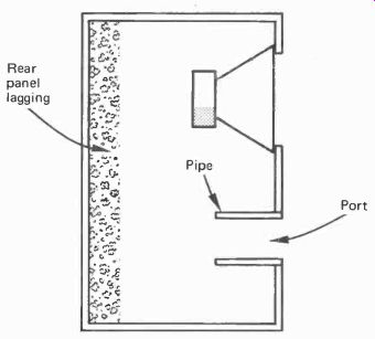
Fig. 23. Bass reflex enclosure.
The air in the inlet pipe is isolated from the rest of the air in enclosure except at its inside end. It has inertia and so has a resonant frequency of its own which is largely independent of that in the enclosure. the pipe is so proportioned that its resonant frequency is the same as that of the cone and enclosure air combined. Having two resonant frequencies the same may seem disastrous in view of what has previously been said about avoiding similar cabinet dimensions to prevent such a situation. However, it is the manner in which the air masses react with each other that gives the desired effect.
At high frequencies the inertia of the air in the pipe is too great for it to respond so the enclosure behaves as if it were a totally sealed cabinet. Performance is thus similar to that of an infinite baffle at those frequencies.
Interaction at Resonances
At resonance, which is in the bass region, the pipe air mass reacts against the springiness of the enclosure air mass and vibrates but in opposite phase to it. We can get an idea of what happens by considering two pendulums of the same mass, hence swinging frequency, hung so that the free end of one strikes that of the other. The first one is driven by a force so that it maintains a constant backwards and forwards motion.
At the first strike, the second pendulum is knocked outward and the first reverses then returns to meet the second coming back. There is another strike, the second is knocked outward again and the process continues.
The second pendulum is kept moving by the first but its direction is always opposite to it. So too the air mass in the pipe moves in the opposite direction to the enclosure air mass and thereby radiates sound that is out of phase with it. This of course is in phase with the sound generated by the front of the loudspeaker cone and the desired reinforcement occurs.
With the air in the pipe moving outward at resonance at the same time as the cone, the decompression inside the enclosure is greater than with an infinite baffle, and when the air moves backward it does so at the same time as the cone thereby increasing compression. Thus the movement of the cone is highly damped at resonance and its excursion is no greater than at other frequencies. This is opposite to its normal behavior by which cone excursion is greater at resonance. It can thus handle a larger signal without driving it beyond the limits at which non linear distortion and straining of the suspension can occur. Its power handling capacity is thereby increased.
Returning to our analogy of the pendulums, if we visualized them as being linked at their free ends with elastic or a spring, we can get a more accurate idea of what happens especially at higher frequencies. The first pendulum is made to swing much faster so that the second when struck hardly has time to move before it is being pulled back by the elastic, and when it begins to respond to this pull it is struck again. So it really doesn't know whether it is coming or going and its inertia prevents it from hardly moving at all. This is just the situation at high frequencies we described for the two air masses which are linked by their mutual elasticity. The higher the frequency the less the response of the second air mass will be.
Let us now imagine though, that the first pendulum is slowed right down. It meets the second one but instead of knocking it on it gently pushes it forward, and when it reverses, the second one does also. So, the second pendulum moves under the influence of the first as before, but this time it travels in the same direction.
This is what happens to the air mass in the pipe at frequencies below resonance. It has insufficient inertia to bounce back and it follows the same movement and direction as that of the enclosure air mass. So it behaves as a simple leak in the baffle and the rear wave emerges out-of-phase to cancel the wave from the front.
Disadvantages
The cancellation effects below resonance produce a very sharp drop in output, up to 24 dB per octave. This is partly due to the high efficiency above resonance which is around 5 dB or three times the output of an infinite baffle enclosure. The fall from this must therefore be more rapid. While the high efficiency is desirable, a rapid drop can result in 'ringing' and other unmusical effects in the bass register. A gentler slope gives better subjective results even if it starts at a higher frequency and thereby curtails the bass somewhat.
Another snag is that only the minimum amount of lagging can be used inside the enclosure because lagging reduces Q, and as the enclosure air resonance plays such an important part in the operation, a high Q is essential. Thus panel resonances and other problems resulting from insufficient lagging may be encountered. The back panel should be lagged though to prevent a reflected wave passing out through the loudspeaker cone.
As all resonant objects store energy then subsequently release it, this happens also with the reflex enclosure. Sound is thereby radiated after cessation of the input signal. This gives rise to a rather muddled effect especially on bass transients such as string bass pizzicato notes.
A further drawback with the reflex enclosure is that air turbulence is generated around the pipe and the vent which can produce noise at high volume levels. With smaller enclosures friction losses around the vent can reduce the advantage of high efficiency.
Auxiliary Bass Radiator
As an alternative to the pipe, a device similar to a dummy loudspeaker is sometimes used. It is a cone suspension without the magnet and coil, its mass serving as a substitute for that of the air in the pipe. It avoids the pipe noise and air turbulence and also serves as a barrier to mid-frequencies which may radiate through a vent from internal reflections. Its mass can be precisely designed for a specific enclosure, and it can be made to resonate at the required frequency in a smaller enclosure than would be possible with a normal vent.
Impedance
With an infinite baffle enclosure, the cone excursions are larger at resonance than at any other frequency, although the acoustic output may not be greater because of the damping introduced by a Q that is less than unity. The back emf which is generated by the coil transversing the magnetic field, is therefore also greater at resonance, as is the opposing current it produces.
Thus the total forward current (signal current minus back current) is smaller. The effective impedance of the circuit is therefore greater. A graph of the impedance of any loudspeaker in an infinite baffle enclosure will show a peak at the resonant frequency. In fact if such a graph is published with the speaker specification, one can determine the resonant frequency from it more easily than from the frequency response chart.
In the case of the reflex enclosure, the cone is physically restrained by the air loading as we have seen, so its excursion is less than it is at the surrounding frequencies. Back emf and current is thereby reduced so instead of a peak there is a dip in the impedance at resonance. However, on approaching resonance from either side, the cone starts a more vigorous motion, but it dies down at the actual resonant frequency.
Thus are obtained two small impedance peaks equally spaced either side of resonance. These clearly identify a reflex speaker. (Fig. 24).
Impedance Resonance Infinite baffle Reflex Frequency
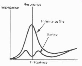
Fig. 24.
Impedance chart comparing infinite baffle with reflex enclosure.
They appear as such only when the two resonant systems are at the same frequency which is when the reflex action is working properly. With small enclosures, some designers tune the tube air mass to a slightly higher frequency than that of the enclosure, and this shows up as a pair of unequal peaks, the lower being the largest.
Enclosure Design
Construction must be sturdy of a dense material to avoid panel resonances as lagging cannot be used except over the back. The formula for calculating enclosure volume is as follows:
( V 4.66 x 10^6 + L ins2 f2 (L + 1.7r)
In which V is the volume of the enclosure in cubic inches; r is the radius of the speaker cone; L is the length of the tube; and f is the resonant frequency of the speaker; all measurements in inches. For this formula the area of the vent should equal that of the speaker cone.
If you prefer to work in metric units the following is an approximate equivalent, all measurements in cm.
V = p ^2( 304 x 10^6 + L) cm^ 2 f2 (L + 1.7r)
The design is quite critical as the two resonant systems must be matched. There is though a quite simple way of tuning an enclosure to get it right. The resonant frequency of the tube depends on its length, so some means of construction must be devised which allows the length to be altered in both directions at least experimentally, until the optimum length has been determined. Once this has been done, the adjustable tube could be replaced with a permanent one of the correct length.
The tuning requires an audio oscillator, amplifier and a.c. ammeter. The oscillator does not have to be anything fancy as long as its frequency can be varied around the resonant frequency of the system. The method is to connect the speaker to the amplifier with the ammeter in series. Next feed a signal from the oscillator into the amplifier input and adjust the amplifier gain and ammeter range to get a readable indication.
Now starting well above the resonant frequency, slowly sweep the frequency of the oscillator down to and below the resonant frequency.
The peaks will show up as two dips in the current reading.
The important thing is to get them both the same. If they are not equal the two resonant frequencies are not matched. So, adjust the tube length until they are. As an alternative to the ammeter a voltmeter can be connected across the speaker, in which case the peaks will show as peaks and not dips. The success of using a voltmeter depends on the amplifier and how much its output voltage is dependant on the load. If the peaks are barely discernable, connect a 5-watt (or larger) wire-would resistor in series with the amplifier and speaker. Almost any value between 5 and 100 ohms will do.
Summary The reflex enclosure enjoyed popularity in the early days of hi-fi because it had a greater bass response than unsealed cabinets, and a higher output than sealed ones. The latter was important in the days of small valved amplifiers. Furthermore the acoustic suspension speaker and infinite baffle sealed enclosure had not then been developed to their present stage.
When they came along, and amplifier powers began to climb, the reflex speaker fell from favor. Its indistinct boomy bass so long a part of the hi-fi scene, was at last recognized for what it was. However, of recent years some manufacturers have developed the reflex system, using various devices including acoustic resistance in the vent to reduce turbulence and the rapid bass roll-off, along with methods of minimizing panel resonances. The result has been speakers giving quite creditable results and a much cleaner bass than their early ancestors.
For the home designer without their experience and equipment though, the reflex enclosure poses rather too many pitfalls. It should be built only on one of two conditions.
Either by following exactly the plans supplied by a reputable speaker unit manufacturer, or purely as a design exercise to try out ideas. In the latter case, the previously mentioned formulae and test method can be used as a starting point.
The Horn
From ancient times the special properties of the horn as an acoustic amplifier have been appreciated and used. It was discovered early that a hollow animal horn would amplify the voice or make quite a loud musical sound, hence no doubt the origin of the name. It has been used widely in musical wind instruments, and also for public-address systems. It is also used for some hi-fi reproducers.
The horn has one major advantage over all other types of speaker system. It also has one major disadvantage. To understand these we need to know just what effect a horn has.
In the case of a loudspeaker cone we have a large mass impelled by a considerable force used to move a slice of air of the same area which is very light. This is like the proverbial sledgehammer being used to crack a walnut, or, an illustration we have used before, driving a car at high speed along a flat road in bottom gear.
If the loudspeaker cone is placed at the beginning of a duct that has an increasing area along its length, it first moves a slice of air of small area. This moves an adjacent one of slightly larger area, which moves one that is larger still, and so on. The final large slice actuates the free air at the end of the duct.
Efficiency
Thus the action of the cone is smoothly and progressively matched to the eventual low impedance of the free air. The device is in fact an acoustic transformer, with the force exercised by the cone being applied to maximum effect. As a result of this, remarkable efficiencies can be obtained of over 803/4 this comparing with less than 1% for most infinite baffle speakers. So the theoretical output can be well over eighty times that of a sealed box speakers, or conversely, quite a small amplifier of just 1 watt would be more than adequate for domestic purposes.
The advantage in this is not just a cheaper amplifier. It is quite easy to design a high quality amplifier using class A output stages to provide a couple of watts. It is when high powers are needed that the problems start. To avoid massive heat dissipation, class B operation is commonly used, but this generates third harmonic crossover distortion. Various ploys are used to minimize this. Most vary the transistor bias according to signal amplitude so that at high levels at which crossover distortion is least noticeable, the output stage operates in class B, but at low levels it is biased to class A.
Other arrangements have been employed such as feedforward, current dumping, and pulse-width modulation, with varying degrees of success. Some of these produce very low measured distortion, but often still lack the clean musical sound of pure class A. All are just trying to get class A quality at high power. If then a loudspeaker is so efficient as to enable a low power class A amplifier to be used, this can be considered a major advantage.
Flares
The manner by which the horn increases in area can affect its performance. The simplest configuration is a cone, but it is by no means the best. Reflections can occur between the sides which cause interference and irregular frequency response as well as distortion. The ideal is an exponential horn by which the area increases according to an exponential law (Fig. 25).
This gives optimum air load matching and prevents internal reflections.
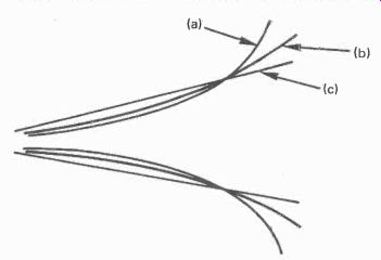
Fig. 25. Horn flares. (a) Hyperbolic (b) Exponential (c) Conical
Because there is a mathematical law governing the expansion of area, it follows that there is a fixed relationship between the length of the horn and the size of the flare at its end. A large flare must have a long passage leading to it.
Another factor related to size is the frequency response. The shortest wavelength that the horn will reproduce is twice the diameter of the throat or start of the horn. The longest wavelength it will radiate is equal to twice the flare diameter. It is this last fact that gives rise to the big disadvantage. To obtain a response down to 100 Hz, a flare of 5.6 ft (1.7m) is required. For a 50 Hz response it would have to be 11.2 ft across.
The length of the horn needed for a specified flare and throat area is given by:
L- log A- log a x 4,000 f x loge
In which L is the length of the horn in cm; A is the area of the flare, and a the area of the throat in cm^2; f is the lowest frequency; loge is 0.4343.
A horn following a hyperbolic area increase gives a response to a lower frequency than that of the exponential horn, but the roll-off below it is more rapid. The area increase from the throat is more gradual, so the sound pressure is greater there, to fall off more rapidly near the flare. This pressure variation along the length results in distortion being generated.
Throat Design
The throat needs to be of as small an area as practically possible in order to obtain a good high frequency response, because as we have already seen the shortest wavelength the horn will produce is twice the throat diameter. However, the cone needs to be larger than this in order that it will function effectively, so this means that the area immediately in front of the cone must narrow down to the start of the horn proper. A region of high pressure is thereby created in front of the cone which could cause it to respond in a non-linear fashion and so produce distortion. To avoid this the pressure is equalized by a sealed chamber placed behind the cone.
Another problem is that sound pressure from the central and outer areas of the cone could arrive at the centrally located throat at slightly different times because of the difference in spacing from it. Cancellation effects at various frequencies could thereby occur. This is prevented by introducing a plug with holes in it in front of the cone to delay some of the pressure waves so that they all arrive at the throat at the same time.
Domestic Hi-Fi Horns
Most of the design details we have discussed relate to the long metal public-address horns often seen in sports stadiums and other outdoor locations. We have done so in order to show what principles are involved and the problems that are encountered when attempting to use the horn for domestic hi-fi. When listening to public-address horns, one fact is inescapable, they are very much lacking in bass because of the limited length and area of the flares. Even so, the horns are much bigger than most people would like to accommodate in their living rooms.
As we saw in an earlier section, horns are used successfully in front of tweeters to improve the efficiency of those such as the ribbon, that have a low acoustic output. It is the bass frequencies that causes the problems.
Some public-address horns are folded back on themselves in a configuration termed a re-entrant horn. This helps with the length but does nothing to reduce the size of the flare. Some form of folding is the only way a horn could be used domestically.
The usual arrangement is to mount the driver facing forward in a large cabinet. It is the rear wave that is horn loaded by forming a path of approximately exponentially increasing area by means of a system of wooden partitions. The path so formed is folded to make best use of the available space within the cabinet, and finally terminates in a large flare opening (Fig. 26). The partitions do not have to be lagged, as the sound pressure waves do not meet them head on as they do with sealed enclosures, but travel parallel to them. In fact lagging would destroy the smooth progressive nature of the path.
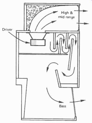
Fig. 26. Example of domestic folded horn. Highly efficient, low distortion,
but large and tricky to manufacture.
One problem that is overcome by this method is the production of high frequencies. These are radiated directly by the front of the speaker and so are not limited by the area of the throat or start of the passage. It would be difficult to obtain a small throat area using a normal bass driver, and a chamber so formed would be highly resonant and so color the reproduction.
Any such design using wooden partitions however ingenious, cannot follow a true exponential law, and as a result efficiency suffers. This is not a major drawback through, as efficiencies of 40% are common which still compares very favorably with every other type of enclosure. More serous are the reflections which can produce colorations. However, with a good design, these are not too serious, and the horn sounds cleaner than most infinite baffles or reflex enclosures.
The major problem though remains: size versus bass response. Some models are designed with a rear opening so that the flare size can be augmented by mounting the enclosure tight across a corner of the room. The walls are thereby used as an extension of the horn. The shape is quite wrong, but a useful improvement in bass response can thereby be achieved.
Transmission Line, Labyrinth
The transmission line or labyrinth type of enclosure has many advantages over other types of enclosure, but like all the others has some practical disadvantages too. It gets its name from the electrical transmission line used to convey audio or video signals. If the end of such a line is left unconnected signals travelling along it are reflected back to the source from the open end. In the case of video signals, a monitor connected at some point along the line will exhibit 'ghosting', spurious outlines appearing on the right of all vertical objects in the picture. These are due to the reflected signals arriving back slightly later than the outgoing ones.
If though the line has a high degree of loss, or a matching circuit is connected to the end, the signal is totally absorbed and none is reflected back. As a high loss would severely attenuate the signal, the latter course is adopted by connecting a terminating resistor of the same value as the line impedance across its end. Reflections are thus eliminated.
In the case of the speaker enclosure, a long path that is filled with acoustically absorbent material is provided, down which the rear wave is sent. It thus behaves like a 'lossy' transmission line. Whatever small amount of energy reaches the end, any that may be reflected back undergoes further loss on the return journey so that little if any arrives back at the loudspeaker to modify its cone motion. Thus one of the major sources of distortion of the infinite baffle enclosure is eliminated (Fig. 27).
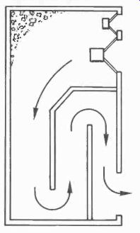
Fig. 27. Typical transmission line enclosure. The path is often tapered
to reduce section resonances.
In practice the end of the line is left open so that what is left of the rear wave escapes into free air. What happens then depends on the amount of absorbent in the line. If a minimal amount is included, a fairly strong rear waves emerges, but because of the time taken to travel along the line it is in phase with the front wave and so reinforces it. This occurs when the length of the line is a quarter of the wavelength of the emerging sound.
The effect is thus similar to that of the reflex enclosure but without the strong air and possible panel resonances. An air resonance does exist but it is damped by the absorbent material and so is of a much lower Q and thus produces less coloration.
The reflex enclosure on the other hand must be undamped because its operation depends on resonance.
Like the reflex system though, the bass roll-off is rapid below the quarter-wavelength frequency which is usually chosen to be at the speaker cone resonant frequency. When so chosen, the cone excursion, as with the reflex speaker, is curtailed by the air load and so permits greater power handling and less distortion at that frequency.
If alternatively, the line is well filled with absorbent material, the emerging rear wave is weak and does little to reinforce the front wave, However, the roll-off is more gentle, and if the length of the line is made slightly longer than the quarter wavelength of the cone resonant frequency, the roll-off can be extended a little lower still.
Resonant Pipe
The transmission line enclosure behaves like an organ pipe, closed at one end and open at the other. As such it has a fundamental resonant frequency which can not only color the reproduction by over-emphasis of that frequency, but as with all resonant objects, it stores energy and releases it after the signal has ceased so giving a spurious output.
The resonance can as we have noted, be damped by filling with absorbent material. A closed pipe (closed at one end) has at resonance a node of minimum air particle motion at the closed (loudspeaker) end, and an antinode of maximum motion at the open end. Effective damping requires a greater concentration of material at the antinode where air motion is greatest, while less is required at the node. So the material should be packed more tightly at the vent.
In addition to the fundamental resonance, a pipe has harmonic resonances at multiples of the fundamental frequency. Fortunately, a closed pipe does not generate even harmonics, so second, fourth, sixth, etc. harmonics present no problem. Odd harmonics are generated though, and so need attention (Fig. 28).
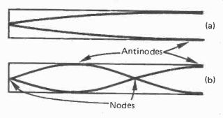
Fig. 28. Disposition of nodes (locations of minimum air motion) and antinodes
(locations of maximum air motion) in a closed pipe; at (a) fundamental,
and (b) 3rd harmonic.
The third harmonic has antinodes at the one-third and open end positions. The extra packing at the open end to dampen the fundamental will thus do the same for the third harmonic, also some extra packing at the one-third position will be required.
The fifth harmonic has antinodes at the one-fifth, three-fifths and again at the open end. Some extension of the extra material back from the one-third position can take care of the first antinode and the final one at the open end is already damped. A little extra just over halfway, deals with the middle one. Exact positions are not critical as the air motion varies gradually along the length from node to antinode, so somewhere near the antinode will effectively dampen it.
Higher odd harmonics are weak and are suppressed by the existing absorbent.
Partitioning used to form the line is not subject to violent pressure differences from one side to the other, as in most cases the two sides are adjacent sections of the transmission line path. So panel resonances are not a problem and can be un-lagged providing they are of reasonable thickness.
Sensitivity is greater than the infinite baffle though less than the non-airtight cabinet and nowhere near that of the horn. It therefore does not require a high power amplifier, moderate power is in most cases sufficient. Depending on the driver(s) chosen it may even be possible to use a low-to-moderate power class A amplifier and thereby improve results even further.
It is thus theoretically possible to get sound reproduction virtually free from air and panel resonances and non-linear cone excursion and with a natural bass response. So what are the snags?
Practical Problems
As with the horn, size is the chief concern, the rear line or passage must be at least 8 ft long, which is about a quarter wavelength of 35 Hz. However, unlike the horn it does not have to increase in area throughout its length; in fact ideally, the area should remain constant, the same as that of the speaker cone. So although an 8ft passage cuts out the possibility of a bookshelf transmission line speaker, it does not have to be quite the monster size required for a full-range horn. Even so the speakers are usually much larger than the average infinite baffle and a pair can occupy a fair amount of space.
Most of the problems arise from the necessity to fold the passage into a form that can be accommodated in a practical enclosure. One of the snags here is each section so formed tends to have a resonant frequency of its own together with harmonics. To minimize this effect, in some models the passage is tapered so that the area gradually diminishing toward the end. This lowers the frequency of the third and fifth harmonic which in itself is not detrimental. Another effect of tapering though, is to produce back pressure which could influence cone movement and to increase the sound pressure along the length which is opposite of 'losing' it as we want. In such cases there is a substantial output from the vent so the reflex mode must apply.
Another effect is that the partitioning on the bends can reflect waves back up the previous section, and can also absorb and release energy to add coloration. However this and the individual section resonances can be greatly reduced by the efficient reflection of sound waves around the bends. If this is done effectively, the passage behaves virtually as if it was in one straight run. This is one of the problems tackled in a novel way in the Kapellmeister speakers described in the final section.
The provision of a long folded passage means plenty of woodwork to say nothing of design ingenuity. As a result, commercial speakers are expensive, and D-I-Y designs rather laborious and difficult to construct. These problems too have been carefully considered and minimized along with that of size in the Kapellmeisters.