It is common practice to employ separate drivers to handle the treble and bass frequencies, and sometimes the mid frequencies too. Occasionally a sub-woofer is used to extend the bass about an octave below that of the bass driver. A separate enclosure is needed for this and because we cannot determine the location of very low frequencies, a single unit supplied from both stereo channels is usually effective. Super tweeters are sometimes used to extend the response well beyond the content of most program material and beyond the human audibility range too.
An essential requirement in such multiple driver systems is a circuit for separating the frequency bands that feed the different drivers. These are known as crossover networks and consist of an arrangement of two basic components, a capacitor and an inductor or coil.
Capacitive Reactance
Firstly, let us consider exactly what a basic capacitor is. It consists of two conductors having a large area in close proximity to each other. When a voltage source is connected across it, electrons are drawn from one surface and rush through the source to the other. There is thus a deficiency on the first and a surplus on the second. The capacitor is then said to be charged and if the source is disconnected, a voltage equal to that of the source can be measured across the capacitor.
Charging a capacitor is not like filling a bottle, in that once it is full it will accept no more. If the source voltage is increased, the charge will increase right to the point when the insulation between the surfaces breaks down. It is more like inflating a balloon which will take more and more until finally it bursts.
At the instant of connecting the capacitor to the source, the current flow is large as there is virtually no opposition to it.
But as it becomes charged, its rising internal potential opposes that of that source thus reducing the charging current. This decreases until the internal potential and source voltage are equal, at which point it ceases. The charging curve is therefore not linear but exponential.
If removed from the source and applied to an external load, the capacitor will discharge in a similar manner, the current decreasing as the potential falls. Even without an external load, a capacitor will discharge itself in time because of internal leakage through the imperfect insulation.
If a capacitor is partly charged, and then the source voltage is reversed, it will discharge and begin to charge to the opposite polarity. If the source is again reversed before the recharge is complete, it will discharge once more and start a further charge to its original polarity. This process can be kept going indefinitely, with current flowing in and out at each polarity reversal.
So an a.c. source will keep current flowing, providing the reversals occur before the capacitor is fully charged. It should be noted that as the maximum current flows before the voltage starts to rise, maximum current and voltage do not occur at the same time. The current leads the voltage by 90°.
If the reversals are very rapid, charging and discharging will always take place at the start of the curve where the current is greatest. If reversals are slow, the capacitor will be well charged and the current be reducing before the next reversal comes. So, the average current passing through a capacitor is dependant on how rapid the reversals are. In other words, the magnitude of the current depends on the frequency of the a.c. source, the higher the frequency, the greater the current.
It also depends on the size of the capacitor. One having a large capacitance takes longer to charge and discharge, and so will still be operating at the early high-current portion of its curve at the slower low frequencies. The larger the capacitance then, the higher the current.
Both frequency and capacitance are therefore factors governing the current flow through a capacitor. They are combined in the property termed Capacitive Reactance, symbol X,, which is to a capacitor what resistance is to a resistor, hence the unit is the ohm, Formula for calculating it is:
1 / 2 pi fC
where f = frequency in Hz, and C = capacitance in Farads.
For microfarads the formula becomes:
10^6 / 2 pi fC
The capacitor thus offers a high impedance to low frequency signals and a low impedance to high frequencies so enabling it to be used as an element in frequency selective filter circuits.
Inductive Reactance
When a current flows through a straight wire, a circular magnetic field surrounds it which is made up of individual lines of force. If the wire is wound in the form of a coil, the lines link up to produce a concentrated field which form loops passing radially through the center of the coil and around its exterior.
When the current starts to flow, the field does not appear instantaneously, but rapidly builds up from zero. Likewise when the current ceases, it collapses. In both instances the lines of force cut across the windings of the coil. It is this action that gives the coil its peculiar property.
Whenever a magnetic line of force cuts across a conductor, it induces an electromotive force (EMF) in it. This is the principle on which all electric generators depend. It matters not whether the conductor moves or the magnetic field, nor does it matter whether the field is produced by a permanent magnet or an electromagnet.
It follows that when the field produced by a coil builds up or collapses and so cuts across its own windings, an EMF is induced in them. This always opposes the original voltage that produced the current, because its polarity is opposite to it.
Thus the effective voltage acting in the circuit is that of the applied voltage minus the self-induced voltage.
In the case of a d.c. supply, the effect is momentary. When the current starts to flow, the opposing EMF inhibits it so that it builds up slowly to its maximum. After this, the field is stationary and so has no effect. On removing the applied voltage the EMF generated by the collapsing field tries to perpetuate the current. Quite high voltages can be induced by the collapsing field.
With a.c., the field is constantly changing and so the current is continuously opposed. This is the property which is termed Inductive Reactance. Because the current builds up slowly it lags behind the applied voltage by 90° so maximum current and voltage do not occur at the same time.
The opposing or back EMF is proportional to the speed of the changing field, being highest when the speed is greatest. As the rate of change increases with frequency, it follows that the reactance is not constant but increases as the frequency rises.
It is also dependent on the inductance of the coil. This is a rather complex factor depending on the total number of turns, the turns per inch, length and diameter of the coil and the number of layers. Also affecting inductance is whether the coil is air-cored, is iron-cored (increases inductance) or is brass-cored (decreases inductance). The latter applies when brass slugs are used for tuning r.f. coils. The formula for inductive reactance is:
XL =
In which XL is in ohms, f = frequency in Hz, and it is inductance in henries.
The inductive action of a coil is reduced by its d.c. resistance so dividing the reactance by the resistance gives a quality (Q) factor. The formula then is:
XL Q- R
Thus at low frequencies the inductor offers minimum impedance, but at high frequencies the impedance is also high.
Along with the capacitor which has the opposite effect, it thus affords a means of separating an audio signal into bands suitable for driving multi-speaker systems.
First-Order Network
Combinations of inductors and capacitors are arranged to provide low-pass, high-pass, or band-pass characteristics.
These are used to supply the bass driver, treble unit, and mid-range speaker respectively.
The simplest circuit is of a single capacitor connected in series with the tweeter. This prevents low frequencies reaching the tweeter which would seriously damage it. Both low and high frequencies are fed to the bass unit which will reproduce some of the highs due to cone flexure. Having two speakers reproducing high frequencies in close lateral proximity will result in interference at certain angles, reinforcement taking place at some frequencies and cancellation at others. Because of this the circuit is used only in cheap radio units, but it can be and is used effectively with co-axial speakers where the tweeter is mounted within the bass cone.
To avoid interference effects, an inductor is connected in series with the bass unit which filters out the high frequencies, so we have a capacitor feeding the tweeter and an inductor supplying the woofer. This is known as a first-order network each leg attenuating the signal outside of its pass range at the rate of 6 dB per octave (Fig. 30).
The point where they overlap is known as the crossover at this point the response of each driver is -3 dB or half power. As we saw earlier, current through a capacitor leads the voltage, whereas it lags through an inductor. In the first-order network, the lead and lag is 45° so cancelling to produce an in-phase signal from the drivers at the crossover frequency (Fig. 31). The two half-power signals thus add to produce full power and so the response through the crossover region is flat.
The formula for calculating the theoretical values are:
L Z x 10^3 2 pi fc C-
10^6 2 pi fcZ
In which L is the inductance in millihenries; C is the capacitance in microfarads; Z is the speaker impedance; and fc is the crossover frequency.
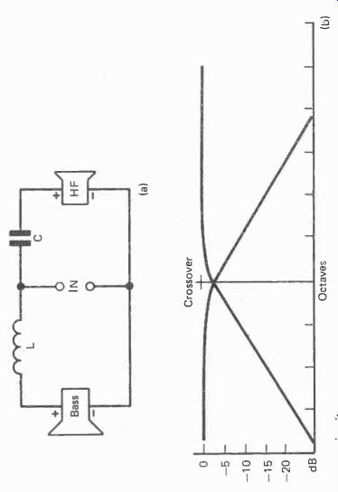
Fig.
30. (a) 1st. order crossover circuit. (b) Frequency response of respective
drivers falling at 6d8/octave, -3d8 at crossover.
Octaves
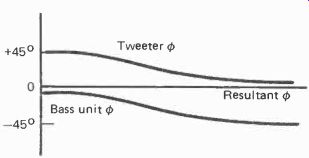
Fig. 31. Phase angles of tweeter and bass unit in 1st. order network.
Resultant is zero phase shift.
There is a snag here though. The 6 dB per octave roll off is too gentle. It means that at two octaves from the crossover point, both drivers are handling a -12 dB signal that is outside of their respective bands, while at three octaves there is still a- 18 dB signal.
The problem arises when the natural frequency roll-off of one of the drivers coincides with that of the filter. Then the total roll-off for that driver is augmented and made steeper. So the two roll-offs for the two drivers are non-symmetrical, one being steeper than the other. This produces a power level of less than -3 dB for the affected driver at the crossover frequency resulting in a dip in the response (Fig. 32).
A further snag lies in the fact that the tweeter will be fed with substantial proportions of the bass signal which would not only produce distortion due to overloading it, but could result in damage. Yet another undesirable factor is that the tweeter resonant frequency which should be kept below the crossover point and so out of the range it is required to handle, can be excited. The result is a peak at that frequency which is generally in the mid-frequency range.
Higher Orders
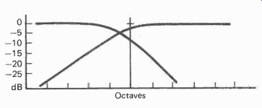
Fig. 32. The natural roll-off of the base unit can accentuate that of
the crossover circuit to produce an asymmetrical response with a deeper
trough at crossover point below-3dB level.
The solution to these problems is to use filters having a sharper roll-off. A 12 dB per octave characteristic can be obtained by adding a capacitor across the bass driver and an inductor across the tweeter. This circuit is a second-order network (Fig. 33), and it is also known as an L-filter because the series and parallel components form an L when drawn in a circuit diagram.
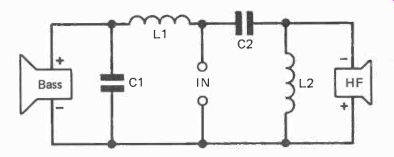
Fig. 33. 2nd. order crossover circuit.
The disadvantage is that the phase difference between the drivers is 180° which produces a dip in the response at the crossover frequency. This can be avoided by reverse connecting the tweeter, but then a hump is produced instead.
A further effect is that all the high frequencies are in an opposite phase relationship to the low, compared to what they were in the original signal.
A musical instrument that is rich in harmonics such as the cello, may have its fundamental and perhaps its second harmonic reproduced by the bass driver and the higher harmonics by the tweeter. Having the tweeter reversed thus changes the relationship and subsequent resultant sound pressure waveform. While the evidence is that this seems to have little audible effect, it is a departure from the tenet of hi-fi that the reproduced signal should correspond as closely as possible to the original.
Sometimes a resistor is included in series with the tweeter and its series capacitor. This is done to attenuate its output when the tweeter sensitivity is greater than that of the bass driver which is often the case. Sensitivities are thus matched to give a uniform response. A bonus effect of this is to reduce the amount of current lead through the tweeter due to the capacitor, and thus the phase difference between the two drivers.
Further components can be added to form a third-order network. This has an extra inductor in series with the bass unit and an extra capacitor in series with the tweeter. The circuit for each section looks like a T so it is often called a T-filter (Fig. 34). The roll-off slope in this case is 18 dB per octave (Fig. 35). The formula for calculating theoretical values is:
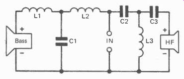
Fig. 34. 3rd. order crossover circuit.
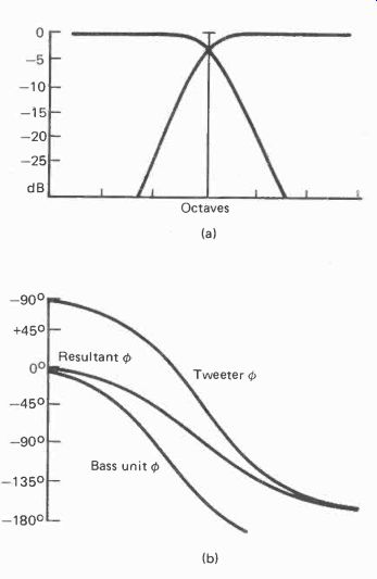
Fig. 35. (al Frequency response of 3rd. order drivers falling at 18dB/octave.
(b) Phase angles of drivers with resultant.

----------------
and
L, = 3L2= 2L3 3Z x 103 4711, C, = 2C2= 2C3
- 20 6 3 3 pi f,Z
Adding another capacitor across the bass driver and a further inductor across the tweeter forms a fourth-order filter. This looks like the Greek letter TT in the circuit and so is called a it filter (Fig. 36). It has a roll off of 24 dB per octave. As with the second-order filter there is a 180° phase reversal so the tweeter can be reverse connected unless other components are included which affect the phasing. Fourth-order filters are rarely used for crossover networks; second and third being the most common.
L4 HF
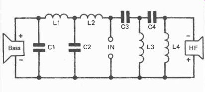
Fig. 36. 4th. order crossover circuit. Roll-off is at 24dB/octave.
The previous formulae assume that the driver impedance is constant which is not the case, it varies with frequency and resonances. They should therefore be considered as a starting point, and the values be modified according to the response of the driver. Sometimes irregularities in the response of the drivers can be partly compensated for by extra components, usually resistors across or in series with the main filter components, but additional inductors and capacitors are often used as well (Fig. 37). It is thus possible to achieve a very flat response for a particular pair of drivers and enclosure. With so many variable factors the design frequently needs to be carried out by computer.
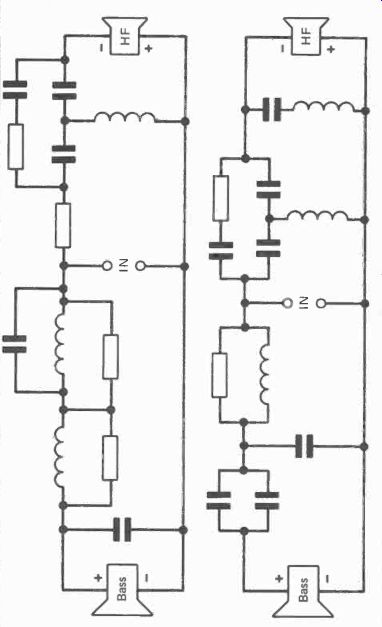
Fig. 37. Two circuits designed by computer to compensate for vagarities
in the driver response. This shows how circuits must be designed for particular
drivers, and substitutions cannot be made without detriment to performance.
For any published design therefore, neither the type of drivers nor values of the network should be changed. They have, or should have been, carefully optimised. It follows that choosing a pair of drivers at random, then using an off-the-shelf crossover is very unlikely to give satisfactory results.
However, some speaker manufacturers do little more than that, and certain ones have been known to substitute a quite different driver with no modification of the crossover filter at all, for the sole reason of lower cost.
Band-pass Filters
When a mid-range driver is added it must be fed via a filter that supplies only the mid frequencies, so it must offer a rising impedance to both high and low frequencies. A first-order bandpass filter consists of a capacitor and inductor in series, while a second-order network has an extra capacitor and inductor, one in parallel across the driver and the other from the junction of the series components (Fig. 38). Here too additional components are often added to compensate for vagarities in the response of the driver.
Whatever the configuration of the network, no parallel component is directly across the input as this would be shunting the amplifier output. Any attenuating resistors are on the amplifier side of the filter because if connected on the driver side, the crossover frequency would be affected.
A further convention is that all inputs are in parallel across the amplifier output so that each section may be considered a separate and independent filter circuit. This means that it is not necessary for both or the three, if a three-way system is used, to be of the same order. Thus a second-order filter may be used for the treble unit to limit the amount of bass it will be fed, while only a first-order circuit is used for the bass driver, as it may be considered less important to limit the high frequencies it handles. While this may result in some interference effects as we have seen, it reduces the phase difference and the effects of 'ringing'
Components
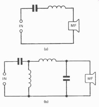
Fig. 38. (a) 1st. order band-pass (mid-range) filter. (b) 2nd. order
band-pass filter.
The capacitors used are generally in the range of 1-10 µF.
Polarized electrolytics with a positive and negative connection should not be used as the signal is pure a.c.. Furthermore, they have a wide tolerances and so a precise value cannot be
For any published design therefore, neither the type of drivers nor values of the network should be changed. They have, or should have been, carefully optimized. It follows that obtained. Non-polarised electrolytics can be used, but other types are preferable.
It may then be wondered why a polarised electrolytic is used for coupling the output stage to the speaker circuit. The reason is that there is d.c. on the output-stage side, on which the signal is superimposed. So the actual voltage across the capacitor never reverses. Its value is not critical because it is not in a frequency selective circuit.
The inductors can be either air-cored or ferrite cored. The ferrite components are smaller because they are magnetically more efficient, most of the generated flux being concentrated in the windings by the core. The disadvantage is that it is possible for the core to saturate at high signal levels thereby varying the inductance, hence also the impedance. The result is harmonic distortion and changing of the crossover characteristics.
Air-cored inductors do not suffer from this possibility, but they are larger and heavier. A problem can arise from the large leakage field which can interact with any other inductor within range and so introduce mutual coupling between them. The effects can be strange and unpredictable. All coils but especially air-cored ones, should be mounted well apart, and if possible with their axes at right-angles.
A printed circuit board is the usual method of interconnecting the components, but however the components are connected, they should be fixed securely with no possibility of adjacent ones touching and thereby able to produce buzzes or rattles when subject to high level sound waves.
Ringing If the signal applied across a capacitor ends abruptly, a charge is left which subsequently discharges through any parallel circuit. In the case of a crossover filter this will almost certainly include the associated driver. Thus terminating transients in the signal are blurred.
A similar effect occurs in the case of an inductor. An abrupt cessation of current flowing through it causes a rapidly collapsing magnetic field which cuts across its own windings.
This generates a voltage that produces a current through any parallel circuit. In the case of a collapsing field, the current so produced is of the same polarity as the original. So the effect is to sustain the current after the signal has ceased. Again a blurring of terminating transients results.
By themselves these overhang affects may not be too bad, but there is worse to follow. The induced current in the inductor recharges the capacitor, which when the current ceases, discharges back through the inductor. So another field builds up which when it collapses, produces further current to recharge the capacitor again.
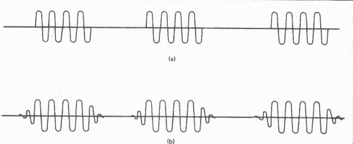
Fig. 39. Tone burst test. (a) A burst of signal at one frequency is
chopped at regular intervals by periods of zero signal. When picked
up by a microphone and displayed on an oscilloscope the result should
look like this. (b) Slow starting and continuing oscillation when the
signal ceases often occurs at the crossover frequency producing a muddy
indistinct effect called 'ringing'.
Thus current surges backwards and forwards in oscillatory cycles until the losses in the circuit reduce it to zero. The effect which is known as ringing, is greatest at the crossover frequency and can be clearly seen on tone-burst oscilloscope traces (Fig. 39). It is also greater with the higher order filters which have more reactive components. This is one reason why first-order filters are sometimes employed for bass drivers and fourth-order circuits are rarely used at all.
There is another possible effect. Negative feedback from the output of the amplifier is commonly applied to earlier amplifier stages. Any spurious harmonics generated within the loop are thus fed back out of phase and so are self-cancelling as they pass through the final stages.
The effect is to considerably reduce distortion generated within the feedback loop, but it can only do this if the fed-back signal is truly out of phase at 180°, any delay causes phase shift and could even turn into positive feedback thereby increasing distortion instead of reducing it.- Now, the oscillatory voltages generated by the crossover filter, appear at the amplifier output terminals, and so are fed back to the earlier stage along the feedback path. They thus appear amplified in negative phase back at the output stage.
However, the reactive crossover components cause a phase shift so that they arrive too late to cancel the original oscillation. Instead, they tend to make matters worse by adding to it.
So some amplifiers that have a low distortion specification on paper achieved by heavy negative feedback, can sound worse than those having higher theoretical distortion due to a more modest feedback level. As the precise effect depends both on the amplifier feedback conditions and the nature of the speaker crossover network, this is one reason why some speakers sound better with certain amplifiers than others.
Cone Oscillation
Damping Another reason for many matching anomalies and a further shortcoming of the crossover circuit, is its effect on amplifier damping. When the signal ceases the cone tends to oscillate to and fro for several cycles before coming to rest due to the springiness of the suspension. Spurious sounds are thus generated.
These cone oscillations generate a back EMF that produces current which sets up a magnetic field around the coil that opposes the cone motion. The oscillations are thus self-dampening. The same effect reduces peaks in the speaker frequency response. If the cone motion at one frequency is greater than that of the others for the same input level, the back EMF and current is also larger. So the opposing force is greater and the excess cone motion is reduced.
The only path for the back current is through the amplifier output stage. As the damping depends on the back current, it also depends on the total resistance it has to encounter, the lower the resistance the better.
A figure is often quoted in amplifier specifications for damping factor. This describes the ability of the amplifier to dampen spurious speaker cone motion by providing a low resistance shunt path. Output stage internal resistance is much lower than the specified output impedance, and the damping factor is the ratio between the two. Factors of 20 are nowadays considered low, and some go as high as 1,000. Taking a typical damping factor of 100 and the usual 8 ohm load, this gives an internal resistance of 8 = 100 = 0.08 Z. Connected directly across a driver, such a low resistance permits a high back current and very effective magnetic damping.
However, when a crossover circuit is employed, each driver has at least one component in series with it that has reactance and in some cases also a resistance, of several ohms. These effectively limit the back current and make nonsense of those high damping factors. The higher the order of the filter, the more components there are in series.
It can be seen then that the crossover network has many vices and so is generally regarded as a necessary evil. The problems and ill effects arising from a two-way crossover are bad enough, but these are greatly compounded with three or more drivers. Even experienced manufacturers often fail to get it right, which is why multi-driver speakers appear now to be going out of fashion.
One well-known maker staged a demonstration of his loudspeaker range at a London hi-fi show a few years ago.
Most of the range sounded good and there was virtually no tonal difference when different models were switched in for comparison. This is how it should be, any difference in tone indicates coloration by one or both of the units being compared. The only difference a larger size should make is to give a better account of the lowest musical octave, but as this part of the scale occurs only occasionally, for much of the time the speakers are indistinguishable.
There was though one model which had a noticeably different tone and lacked the smoothness of the others. It was assumed that this was the cheapest of the range, but investigation revealed that it was in fact the dearest, and the only one to have three drivers; all the others had two.
The poor results were excused with the thought that it might have been due to the acoustics of the demonstration room or bad positioning of the loudspeakers. However, two years later, the same range was demonstrated at a different venue no doubt with different units, but the result was the same. The three-driver speaker sounded different and inferior to all the others.
Dispensing With The Crossover Network
A necessary evil it has been called, but is it really necessary? There are several different options that can be followed. One is the electronic active crossover. Most of the problems arise from separating the frequency bands at high power in the output circuit. As we have seen, this causes phasing differences, ringing, feedback, and impairment of amplifier damping of spurious cone motion and response peaks.
All of these are eliminated if the frequency division occurs earlier in the chain, before the main power amplifier. It can be done quite easily, but it necessitates using two amplifiers for each channel, one for bass and the other for treble. An advantage of having two amplifiers though, is that the gain of each can be adjusted to compensate for different driver sensitivities. If required, tailoring of the response can be built-in for specific drivers as with the conventional crossover filters, but an off-the-shelf crossover is likely to be quite satisfactory.
Another method of using a tweeter without a crossover is to use one of the Motorola piezo tweeters. Their impedance rises as the frequency falls, being around 1,000 ohms at 1 kHz, and increasing according to an exponential curve below that. There is thus no danger the unit being damaged by bass signals and so can be connected directly across the bass driver.
Because the impedance curve is exponential, the output drops off rapidly below about 3kHz, in one model at the raze of 24 dB per octave. If a bass driver can be selected that has a similar rapid fall-off above that frequency, all the advantages of a high order crossover filter are obtained with none of the disadvantages. In addition, response of these piezo tweeters extends up to 40 kHz, an attraction to those wishing to play the game of frequency-response one-up-manship! Of more practical importance is the low harmonic distortion of 0.75%.
The level can be adjusted by means of a 200-ohm variable resistor in series with the tweeter.
This solution, in common with that of the electronic active crossover, although eliminating the loudspeaker crossover network, still suffers from the off-axis interference effects obtained by having two drivers.
These are virtually eliminated by the coaxial speaker which has two cones in which the treble cone is mounted within the cavity of the bass. A crossover circuit may be necessary, but in some cases it is no more than a single capacitor in series with the treble coil. This is possible because the coaxial cones radiate coherent sound at all angles so there are no phase differences at off-axis locations. Shadowing effects of the treble cone at mid frequencies may be experienced and also they may be internal reflections between bass cone and the treble unit with some models.
So to the final solution, which is using a single full-range driver. These rely on cone flexure whereby the central areas of the cone move independently of the outer ones at high frequencies. The active cone area increases as the frequency falls until the whole cone moves at low frequencies. It thus performs as a tweeter, mid-range unit and bass driver all in one.
This may seem to be a backward step to the early lo-fi days when only single speakers were used and frequency response was limited. Uncontrolled cone flexure occurred then, not by design, but as an inevitable result of using paper cones. It produced distortion and its effect on the upper frequency response was not appreciated. It was thus considered an evil to be overcome by the search for more rigid cone materials.
Since then the effect has been studied, and research carried out to produce cones in which the flexure is controlled so that the frequency range is extended to hi-fi standards with minimum distortion. The success of such units has been increased by parallel research into enclosure design.
A practical advantage they possess over separate tweeters is that the tweeter cone surround like any moving-coil unit rarely absorbs all the waves that travel outward from the cone center.
They are consequently reflected back to produce standing waves and distortion. With a full-range driver, the treble is produced only by the central cone area, so the whole of the rest of the cone serves as a buffer between it and the cone edge, just as if it were a super surround. This effectively absorbs the outward going waves, thereby eliminating reflections and giving a more accurate h.f. response.
Most of the objections to a single driver are a hangover from the early days. Loudspeaker cones made large bass excursions in unsealed cabinets due to insufficient air loading and undamped cone resonances. They thus were often driven into non-linear operation, and so when reproducing high frequencies as well, produced intermodulation distortion.
Doppler distortion also occurred whereby the pitch of the high frequencies was successively raised and lowered at each forward and backward bass excursion of the cone.
With bass reflex enclosures and to a lesser extent transmission line speakers, the low frequency excursions of the cone are restricted around the resonant frequency. With a well-damped infinite baffle enclosure of moderate size the cone bass excursions though greater than these, are not excessive. So, intermodulation and doppler distortion are generally below the threshold of audibility in such enclosures operating at domestic volume levels. They thus offer no real objection to the use of single full-range drivers.
Although the frequency range of a single full-range speaker is not quite as great as can be obtained from separate bass and treble units, it is not far short, and the best full-range drivers can approach the full range of human audibility. Many are actually better than some multiple driver speakers.
Really, the use of multiple drivers, desirable in the early days of hi-fi, is now far less so, and can even be considered undesirable. It has persisted as a status symbol, the 'my speakers-have-more-drivers-than-yours' syndrome, and of course the manufacturers with an eye to business have catered for it.
So, at the expense of a slight curtailment of frequency range, all the vices of crossover networks are avoided, a fully in-phase sound propagation at all angles is achieved, maximum damping by the amplifier of spurious cone excursions and response peaks is obtained, high frequency cone standing waves are reduced, and the lack of interaction between crossover circuit and amplifier feedback loop, means that the speaker will perform well with any amplifier. Indeed a trade-off well worth considering!