Low-cost sensor gives temperature reading on a DMM
IF YOU own a digital multimeter (DMM), it can be made to give temperature readings for a small expenditure in parts and effort. When a small forward bias is applied to a conventional silicon diode, the voltage drop across the diode junction changes at a rate of about 1.25-mV/°F (2.24-mV/°C). Thus, a low-cost and readily available diode such as the 1N914 can be used as a temperature probe.
The bridge circuit shown in Fig. 1 works in conjunction with the sensor diode and a DMM on the 200-mV (low temperature) or 2-volt (high-temperature dc voltage ranges. The displayed digits are the temperature. Note that in Fig. 1, two values are shown for R2, R4, R6, and R7. The values in parenthesis are for Celsius operation, while the others are for Fahrenheit. Capacitor C1 is used to bypass stray signals that may be picked up on the leads.
-------------------------
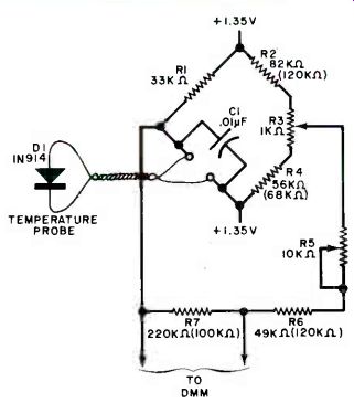
Fig. 1. Diode is one leg of a Wheatstone bridge connected to DMM.
PARTS LIST
C1--0.01-µF disc capacitor
D1--1N914 silicon diode
R1-33 kt2, 1/2-W resistor
R2--82 kO (F) or 12 kO (C) 1/2-W resistor
R3--1-kO pc-mount potentiometer
R4--56 kO (F) or 68 kO (C) 1/2-W resistor
R5--101d2 pc-mount potentiometer
R6-491(12 (F) or 120 kO (C) 1/2-W resistor
Misc.--1.35-volt battery and holder, vinyl or heat-shrink tubing, flexible two-conductor cable, epoxy, solder, etc.
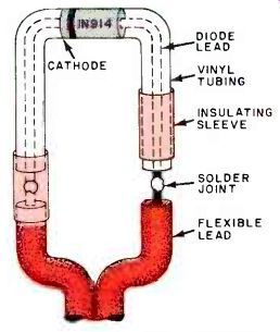
Fig. 2. To make probe immersible, vinyl tubing is added around leads.
--------------------------
Construction. The circuit can be assembled on a small printed-circuit or perforated board. The small circles at C1 indicate the need for a pc pad, or Wire Wrap pin to make the connections to the remote diode.
To make the temperature probe safe for liquid immersion, the arrangement shown in Fig. 2 is used. Preform a short length of vinyl tubing, fill it with epoxy, and "thread" it up the diode leads to make contact with the diode body. Allow the epoxy to thoroughly cure. If desired, a length of heat-shrink tubing may be used. In either case, leave a short length of diode lead exposed for soldering to the flexible cable.
Slide a short length of heat-shrink tubing over the covered diode leads, solder each diode lead to the flexible cable, and then fit the tubing over the solder joint. Shrink the tubing to make a tight fit.
Calibration. The resistance values for R2-R4 and R6-R7 are not critical, but their ratios are. Perform the following calibration tests before changing any resistance value.
Potentiometer R3 balances the bridge to indicate 32 ° F (0 °C) at this temperature. Potentiometer RS is used to reduce the 1.25 (2.24) mV/degree to exactly 1 mV/degree and is also used to set the upper range point.
With R3 and R5 at their center of rotation, immerse the diode probe in a container of finely shaved or crushed ice. Adjust R3 to produce a DMM indication of 32 (*F) or 0 (° C). Place the DMM in the 2-volt dc range, immerse the probe in a container of boiling water, and adjust R5 for a DMM indication of 212(°F) or 100(°C). If you find that R3 is at one end of its rotation, add a parallel resistor in the megohm range across either R2 or R4, depending on the location of the wiper of R3. If RS is at one end of its rotation, add a parallel resistor (also in the megohm range) across R6 or R7. If desired, a 10-turn trimmer potentiometer can be used for each of the fixed resistors and preset for the correct ratios.
Since the DMM will also indicate negative voltages, it will similarly indicate temperatures below those at which it is calibrated. Also, the diode can operate at temperatures above 212 ° F, which is about the limit for the plastic insulation used for the diode leads, so a plastic with a higher temperature rating can be used to liquid-proof the sensor. Or, without such protection, the sensor can be used for dry, or contact, temperature measurements.
Source: Computers and Electronics--Experimenter's Handbook (1984)
Also see: Build ‘LIDITH' -- A 3½-Digit Digital Thermometer
Measure Weak Direct Currents with the Sensitive Micro Meter