by CASS LEWART
Detects oxygen-hungry gases such as carbon monoxide and methane . . . . sounds a warning before dangerous concentrations are reached.
WHEN a lethal fire starts, flame and smoke are not the only killers. Colorless, odorless carbon monoxide gas (CO) has been known to kill or incapacitate people-often far from the fire itself. One factor that makes CO such a stealthy, insidious assassin is its ability to elude conventional smoke detectors. These devices are similarly insensitive to dangerous hydrocarbon gases like methane (CH4), a toxic compound that is the chief component of natural gas.
The Gas Alarm described here has been designed to sound its warning before dangerous levels of poisonous gases accumulate. The Gas Alarm should be considered complementary to, and not a replacement for conventional smoke detectors, as it will not respond to ionized gases generated by fire unless the fire is smoldering in an enclosed area lacking oxygen. This project has the advantage of being self-powered, thus providing portable protection both at home and in hotels or motels when you travel.
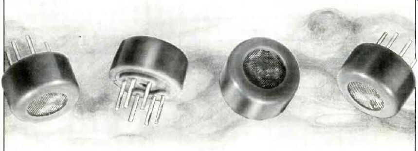
The alarm is based on an inexpensive semiconductor sensor whose electrical resistance changes when its active surface is exposed to gases such as carbon monoxide, methane, butane, and alcohol vapors that have a strong affinity for oxygen. (These are known as reducing gases.) The sensor element is enclosed in a small capsule and protected by a stainless steel mesh, while a low-power heater activates the sensor element and purifies it after exposure to gas.
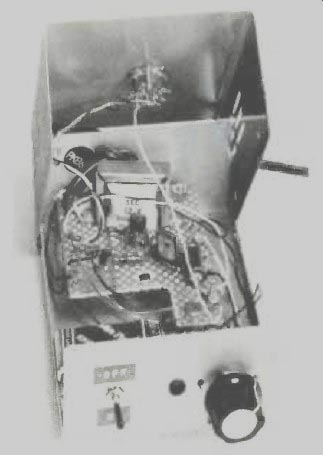
---------- Photo of the author's prototype.
Circuit Operation. As shown in Fig. 1, transformer TI, fullwave rectifier RECTI, resistor R2, and filter capacitor C1 make up the line-powered power supply for 5-volt regulator IC1. Resistor R1, in conjunction with rectifier D1, maintains the charge on the rechargeable cells in B1 , while diode D2 allows BI to power the circuit in stand-by mode when the line power is interrupted. Under these conditions, DI is reverse biased and battery power flows through forward-biased diode D2 to power the circuit.
The regulated output from IC1 maintains a fixed heater voltage for gas sensor TGSI to provide uniform sensitivity. The combination of R3 and LED1 forms a power-on indicator.
When gas is present at TGS1, the resistance of its sensor element drops, raising the voltage applied across calibration potentiometer R4. The rotor of R4 is connected to the gate of SCR1, and when voltage at that point reaches approximately 0.3 V, SCR1 turns on, supplying power to alarm A1. The piezoelectric alarm specified for Al interrupts current flow periodically, so SCR1 does not latch permanently on. Switch Si allows for faster battery charging while the gas sensor is turned off.
----------------
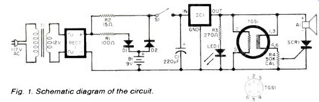
Fig. 1. Schematic diagram of the circuit.
PARTS LIST
A1--Piezoelectric buzzer (Radio Shack 273-060 or similar)
B1-- Battery (six rechargeable 1.5-V cells)
C1--220-µF, 16-V electrolytic
D1, D2--200-V, 1-A silicon diode
IC1--5-V regulator (Radio Shack 2761770 or similar)
LED1--Red LED (optional)
R1--100-Ohm, 1/2-W resistor
R2--15-Ohm 1-W resistor
R3--270-Ohm, 1/2-W resistor (optional)
R4--50-kO linear potentiometer
RECT1-50-V, 1-A full-wave rectifier
S1-Spst switch 6 4
TGSI SCR1--200-V, 6-A
SCR (Radio Shack 276-1067 or similar)
TGS 1--Gas sensor (See note)
T1--12-V, 1-A transformer (Radio Shack 273-1505 or similar)
Misc.--6" x 4" x 21/2" enclosure with cover, pert board or terminal strips, etc.
Note: The following is available from C&R Electronics, Box 217, Holmdel, NJ, 07733: Pretested gas sensor, with socket, for $10.95 plus $1 postage and handling. NJ residents, add 6% tax. Allow 2 to 3 weeks for delivery.
-------------------
Construction. The project will easily fit in a 6" x 4" x 2 1/2" metal cabinet, and all components except the alarm and gas sensor can be mounted on perf board or multi-lug terminal strips using point-to-point wiring.
Mount the socket for sensor on top of the cabinet for maximum exposure to surrounding air, and mount the alarm on the side or back of the cabinet for best audio output. The six rechargeable cells forming B1 can be mounted in readily available battery holders.
Adjustment. (1) Plug the Gas Alarm into a 117-volt ac outlet; (2) rotate CAL control R4 fully CCW for minimum resistance between the SCR gate and ground; (3) apply power and allow the sensor to stabilize for 1-2 minutes, then rotate the CAL control clockwise till the alarm sounds; (4) rotate CAL control CCW till the alarm stops. The alarm is now ready for operation. Test the system by rubbing a drop of alcohol between your fingers, near the sensor. When the alarm sounds, repeat steps two through four.
The rechargeable batteries are trickle charged when the alarm is plugged into an ac outlet, and will be fully charged after approximately 24 hours. To ensure that the batteries are working properly, unplug the alarm and, after allowing it to stabilize with the batteries, repeat the alcohol test described above. The fully charged AA-size batteries should operate the sensor for over an hour during a power failure. For longer standby operation use Cor D-size rechargeable. These will operate the alarm longer, but also require longer charging time. When the alarm is not in use, open SI to protect batteries from discharging through IC1.
Source: Computers and Electronics--Experimenter's Handbook (1984)
Also see:
Build ‘LIDITH' -- A 3½-Digit Digital Thermometer
The LM 339--A Great Comparator