A BATTERY-OPERATED FLUORESCENT LAMP
Portable, high-efficiency light source draws current from a vehicle's 12-volt storage battery, but leaves plenty of charge for engine starting.
BY LAWRENCE M. WALDEN
THE recreational vehicle is becoming more and more popular with campers who want a "home away from home." In such cases, the vehicle's 12-volt battery supply provides a convenient source of power for lighting around the camp. This is very handy, of course; but, for the amount of light they deliver, 12-volt incandescent lamps waste a lot of valuable battery power. Fluorescent lamps, on the other hand, produce good lighting at high efficiency. Unfortunately, they require a dc-to-ac converter.
The low-cost circuit described here not only performs the dc-to-ac conversion, it also provides automatic shutdown when the battery reaches some predetermined voltage level, thus preventing a complete discharge. A LED indicator glows when the turnoff point is reached. Once turned off, the system draws only a few milliamperes.
Circuit Operation. When the 12-volt supply (Fig. 1) is applied to the circuit through fuse FI, switch SI, and the protective diode, D1, multivibrator IC1 starts to oscillate at a frequency determined by the setting of R2. This is approximately 10 kHz. At this time, Q1 is cut off to allow IC1 to oscillate.
As the +12 volts are applied to the R/8/zener diode D2 network, 7.6 volts are applied to the emitters of Q3 and Q4. At this time, the base of Q4 is at zero voltage, thus turning this transistor fully on and developing approximately 7 volts across its collector resistor (R12). This voltage, applied via RI3 to the base of series-pass transistor Q5, turns the transistor on and allows the output of IC1 to pass through R7 to driver transistor Q6.
The latter, in turn, drives power transistor Q7 to its maximum output.
The collector load of Q7 is formed by the 6.3-volt winding of transformer T1. Thus, as IC1 oscillates, a high alternating voltage is developed across the 120-volt winding of T1 and applied to the two series-connected fluorescent lamps (L1 and L2), and across current-sensing resistor R17.
At lamp turn-on, the voltage developed across R17 is rectified and filtered by D3 and C5 and applied across lamp-current-adjust potentiometer R16. A preselected portion of this voltage is applied to the R15/C4 network and to the base of Q4. When this voltage approximates the 7.6-volt emitter reference, Q4 starts to reduce its conductance, thus lowering the voltage developed across collector resistor RI2. This action lowers the bias on series-pass transistor Q5, reducing the drive to Q6/Q7 to lower the lamp drive and reduce the voltage across R17. The circuit stabilizes lamp current preset by R16.
At initial lamp turn-on, approximately 1.3 amperes will flow through Q7 until the fluorescent lamps fire.
This ensures lamp start even in cold weather. Once the lamps strike, the current will range from about 0.9 ampere at 13.2 volts to about 1.1 amperes when the battery voltage drops to near 10.6 volts.
Low battery protection is provided by potentiometer R6. The selected voltage is applied via R8 to the base of Q3. In normal operation, Q3 is cut off since its base voltage is higher than the 7.6 volts applied to its emitter. If the battery voltage drops so that the base of Q3 goes below the emitter voltage, Q3 starts to conduct and its collector current flows through R1O to the base of Q2. When Q2 starts to conduct, the base drive of Q3 is further reduced until both Q2 and Q3 are latched fully on. Once latched on, the collector of Q3 will be approximately 6 volts, which are applied through R11, causing LEDI-the low-voltage indicator-to glow. This voltage is also applied via R5 to the base of QI to bias this transistor fully on. When this occurs, pins 2 and 3 of IC1 become fully positive, thus disabling the multivibrator. At this point, battery consumption drops to about 50 mA, since Q1, Q2, and Q3 are the only active elements. Operating power should now be removed via S1. Capacitor C4 at the base of Q4 is a high value to prevent oscillation, while C3 at the base of Q2 allows the circuit to stabilize before low voltage levels can be detected. Once the circuit is working, it responds very rapidly to voltage drops.
Construction. Since there is nothing critical about the circuit, it can be constructed on a small piece of perf board using point-to-point wiring and sockets for IC1 and the seven transistors. Transistor Q7, transformer T1, power on/off switch S1, fuse F1, and the two fluorescent lamp sockets are mounted on the enclosure.
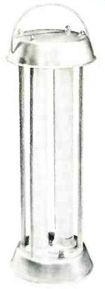
Select an enclosure that can support the circuit board, the transformer, a heat sink for power transistor Q7, and the sockets for the two fluorescent lamps. The two lamps can be mounted vertically on top of the enclosure, and provided with some form of transparent weather protection such as a plastic sleeve. If a metal enclosure is used, it can serve as the Q7 heat sink when a suitable insulator is used. Connection to the +12 volts can be made with a length of conventional two-conductor lamp cord having a cigarette lighter plug at one end. The author used 33 feet of lamp cord.
Since the secondary of transformer T1 can develop as much as 1500 volts peak-to-peak across the output, and as much as 225 volts when the lamps are lit, suitable insulation must be used at these points. Also, keep these voltages in mind when performing the adjustments on the circuit.
Adjustments. Before applying power, remove the connection between low-voltage-adjust potentiometer R6 rotor to the +12-volt end.
Then set lamp-current-adjust potentiometer R16 so that the rotor is at the ground end. Frequency-adjust potentiometer R2 should be set to the R1 side (highest resistance). To make a complete test, use an adjustable power supply between 10 and 14 volts, with a capacity of at least 2 amperes. Connect an ammeter (about 2 amperes) in series with the positive battery connection, and a voltmeter (20-volt range) from the cathode side of D1 to ground. Connect the power source.
When S1 is turned on, the lamps may not fire due to the low frequency of the multivibrator, and about 0.3 to 0.4 ampere will be drawn. Transformer T1 may also make sounds due to lamination movement, which indicates an operating circuit.
Slowly rotate frequency-adjust potentiometer R2 and note that the ammeter current increases and the lamps start to glow. Continue to increase the frequency very slowly until the lamps come to full brightness at a current of about 0.6 ampere. At this point, the supply current will suddenly jump to about 1.2 to 1.3 amperes. Advance the frequency for an additional 0.2 ampere, but not higher, as both output voltage and efficiency will drop.
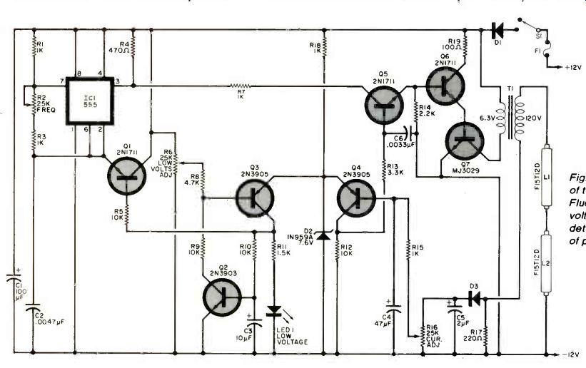
Fig. 1. Schematic diagram of the Battery-Operated Fluorescent Lamp. The
low-voltage cutoff point is determined by the setting of potentiometer R6.
========
PARTS LIST
C1--100-µF, 25-V electrolytic
C2--0.0047-µF, film capacitor
C3-10-µF, 60-V electrolytic
C4-47-µF, 50-V electrolytic
C5-2-µF, 50-V electrolytic
C6-0.0033-µF, 100-V film capacitor
D1,D3-2-ampere rectifier diode
D21 N959A, 7.6-V zener diode
F 1--4-A fuse and holder
IC1--555 timer
L1, L2--15-watt daylight fluorescent lamps (F15T120 or similar)
LED1--Red LED
Q1,05,Q6--2N1711 or similar npn silicon transistor
Q2--2N3903 or similar npn silicon transistor
Q3, Q4--2N3905 pnp or similar transistor
Q7--MJ3029 npn power transistor
R1,R3,R7,R15--1-kO, 1/4-W resistor
R2, R6,R16--25-kO, pc potentiometer
R4--470-Ohm, 1/2-W resistor
R5,R9,R10,R12--10-kO, 1/4-resistor
R8--4.7-kO, 1/4-W resistor
R11--1.5-k Ohm, 1/2-W resistor
R13--3.3-ko, 1/4-W resistor
R 14--2.2-kO, 1/4-W resistor
R17--220-Ohm, 2-W resistor
R18--1-kO, 1/2-W resistor
R19--100-O, 1-W resistor
S1--Spst switch
T1--6.3-V, 1.2-A transformer
Misc.--Perf board, sockets for IC1 and transistors, heat sink and thermal insulator for Q7, sockets (4) for fluorescent lamps, suitable enclosure, length of conventional lamp cord, automotive cigarette plug, transparent weather shield for lamps, adhesives, mounting hardware, etc.
========
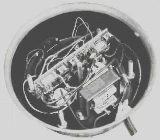
---- Lamp circuit mounted in base of unit.
If desired, the multivibrator can be "fine tuned" using an oscilloscope. To do this, turn the power off, set the controls as described above, remove the lamps and replace them with four 100412, 1/2-W resistors connected in series. Connect the scope leads across R17, and set the scope vertical to 5 volts/division. Turn the power on and note that about 0.5 ampere flows and a 3to-4-volt waveform appears on the scope. Slowly increase the frequency (via R2) until the scope trace peaks at about 15 volts peak-to-peak.
The supply current should reach about 1 ampere at this point. Do not adjust the frequency higher than this, or the efficiency will be reduced. Turn the power off, remove the resistors, and replace the lamps.
To adjust the lamp current regulator with the lamps glowing, slowly rotate current-adjust potentiometer R16 until the current approaches 0.8 ampere and there is a decrease in light output. Then slowly adjust R16 until the current reaches 1 ampere. Lower the power supply to 10.6 volts, then re-adjust R16 for 1.1 amperes current flow. This becomes the maximum current drain at the lowest operating voltage.
Increase the supply voltage from 10.6 to 13.2 volts and note that the light output remains constant as the current decreases. With 12 volts applied, about 1 ampere will flow, and with a 13.2-volt supply, the current drops to about 0.9 ampere.
To adjust the low-voltage cutoff, reconnect R6 to the + 12-volt line, and with the voltmeter still in the circuit, allow a 5-minute lamp warm-up.
Reduce the power supply to 10.6 volts (or other desired low-voltage point) and slowly rotate R6 until the lamps go off and LEDI glows. Recheck this point several times. If, during operation, the lamps go out, the presence of glowing LEDI indicates that the low battery voltage has been reached, and the circuit has not been accidentally removed from the power source.
"Coinshooter" Metal Detector
Advanced circuit reacts to coins and other precious metal objects while ignoring chunks of iron and steel.
BY WILLIAM LAHR
SEARCHING FOR coins and other lost articles along beaches and in parks can be both profitable and fun. The Coinshooter, a novel and inexpensive electronic metal detector, can make such outings more productive. Employing a sophisticated, vlf induction-balance detection system that responds only to the proximity of nonferrous metallic objects, it ignores items containing iron. Moreover, the project can be adjusted to compensate for the soil's mineral content, thus minimizing false indications.
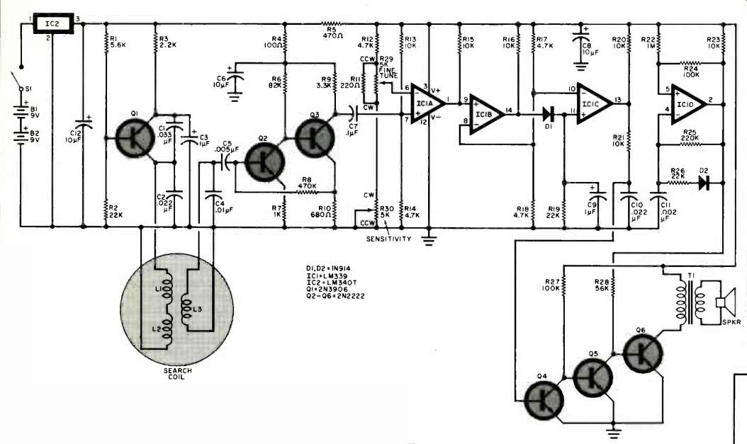
Fig. 1. When the search coil covers a metal object, enough coupling is
created to cause an audible signal at the loudspeaker.
===== PARTS LIST
B1, B2--9-V alkaline battery
C1--0.033-µF, 50-V Mylar capacitor
C2, C10--0.022-µF, 50-V Mylar capacitor
C3, C9--1-µF, 16-V tantalum capacitor
C4--0.01-µF, 50-V disc ceramic capacitor
C5--0.005-µF, 50-V disc ceramic capacitor
C6, C8, C12--10-µF, 16-V aluminum electrolytic capacitor
C7--0.1-µF, 50-V Mylar capacitor
C11--0.002-µF, 50-V disc ceramic capacitor
D1, D2-1N914 silicon switching diode
IC1--LM339 quad voltage comparator
IC2--LM 340T-8 +8-V regulator
L1, L2-Air-core inductor: 175 turns of No. 30 wire wound 9 1/2 inches in diameter (see text)
L3--Air-core inductor: 550 turns of No. 38 enameled wire on 3 1/2" diam.
Q1--2N3906 or similar pnp silicon switching transistor
Q2 through Q6-2N2222 or similar npn silicon switching transistor
The following, unless otherwise specified, are 1/4-watt, 5%-tolerance, carbon-composition fixed resistors.
R1--5.6 kO
R2, R19, R26--22 kO
R3-2.2 kO
R4—100
R5-470
R6-82 kO
R7-1 kO
R8-470 kO
R9--3.3 kO
R10-680 ohm
R11—220 O
R12, R14, R17, R18--4.7 kO
R13, R15, R16, R20, R21, R23--10 kO
R22-1 MO R24, R27-100 kO
R25-220 kO
R28-56 kO
R29-5-kO, linear-taper potentiometer
R30-5-kO, linear-taper potentiometer with shaft-actuated spst switch
S1-Spst switch (part of R30)
SPKR-2 1/4-inch, 8-O dynamic speaker
T1--1kO:8kO miniature audio output transformer
Misc.-Suitable enclosure, perforated or printed-circuit board, single-conductor shielded cable, hookup wire, No. 30 and No. 38 enameled copper (magnet) wire, battery clips, battery holders, circuit-board standoffs, grommets or other suitable strain reliefs for shielded cable, PVC electrical tape or silicone cement or other suitable insulating material, 12-inch-by-12-inch sheet of "4-inch plywood, monofilament fishing line, 3-inch masking tape, epoxy, hot-melt, and PVC glues, 4 feet of 1/2-inch O.D., schedule 125 PVC pipe, 2 feet of 1/2-inch, schedule 40 PVC pipe, 90° elbow PVC pipe joint, 135° elbow PVC pipe joint, tee PVC pipe joint, PVC pipe cap, bicycle steering-bar handgrip, lead buckshot, resin sealant, white paint, solder, hardware, aluminum foil etc.
=========
The Coinshooter can detect a dime at an air gap of four inches or a half-dollar at nine inches. It cannot detect coins buried deep in the ground, but will yield excellent results if the coins are at depths of from 1 to 3 inches.
Unlike detectors that employ conventional beat-frequency oscillator circuits, the Coinshooter does not require the user to monitor the pitch of a continuous tone. Rather, it alerts the user to the proximity of nonferrous metal by generating one or more beeps. Also, it is lightweight (about 2 lb) and well balanced. Total construction cost is approximately $35, and less if salvaged parts are used.
About the Circuit. The Coinshooter appears schematically in Figure 1. Coplanar search coils are formed by placing a receiving coil (L3) over a folded-loop transmitting coil (L1 and L2) so that there is little if any coupling between them unless there is metal present in the search field. A Colpitts oscillator comprising Q1 and its associated passive components generates a 6.2-kHz signal that drives the transmitting coil. Transistors Q2 and Q3 amplify the low-level signal induced across receiving coil L3 when no metal objects are present in the search field so that a 1-volt p-p signal appears at the collector of Q3.
Capacitor C7 couples this signal to the noninverting input of voltage comparator !CIA. The input circuit of the comparator rectifies the ac signal, resulting in the generation of a slightly negative voltage that subtracts from the positive bias voltage supplied by divider RI3R/4. Potentiometers R29 and R30 determine the magnitude of the reference voltage applied to the inverting input of IC1 A and hence the detector circuit's sensitivity. They are adjusted so that the voltages at the two inputs are practically equal.
When the voltage at the noninverting input of the comparator becomes more positive than that at the inverting input, the output terminal (pin 1) switches to the positive supply voltage. This positive pulse toggles comparators IC1B and IC/C, which are connected in cascade and whose inverting inputs are biased to one-half the positive supply voltage. The charging of C9 via DI and the discharging of C9 through R19 stretches the pulse. Transistor Q4 is triggered into conduction by the elongated pulse that appears at the output of IC/C, cutting off Q5.
When Q5 is cut off, Q6 amplifies the tone produced by the audio oscillator comprising IC1 D and its associated passive components. The current flowing through the primary of audio-output transformer TI and transistor Q6 increases the voltage drop across R5, and this upsets the bias applied to the inverting input of IC1 A. As a result, the outputs of IC1 A, IC1 B, and IC1 C go low, transistor Q4 cuts off, and transistor Q5 saturates, shunting the base drive of Q6 to ground and cutting that transistor off. This silences the loudspeaker and allows C8 to charge again to the full positive supply voltage. The higher voltage across the capacitor allows IC1 A to change state again if the nonferrous metal object is still within the search field.
Iron objects or mineralized ground within the search field will produce an increase in the amplitude of the signal at the collector of Q3 and thus a less positive bias at the noninverting input of 1CI A. In contrast, the presence of coins or other nonferrous metal objects within the search field will cause a smaller signal to appear at the collector of Q3 and a more positive bias at the noninverting input of the first voltage comparator. This allows the Coinshooter to locate coins and other items of interest while ignoring nails, bottle caps, and other junk pieces of iron and steel.
When a small nonferrous item quickly enters and exits the search field, the loudspeaker will generate a single beep. If the object enters and remains in the search field, a series of beeps will be produced. Its rate of repetition will vary with the settings of potentiometers R29 and R30, the size of the object, and the distance between the object and the search coil.
The pitch of the beep is determined by the values of C// and the resistances in the feedback loop, as well as by the supply voltage. Its frequency is nominally 1.3 kHz.
Power for the Coinshooter circuit is supplied by two series-connected nine-volt batteries. An IC voltage regulator provides a constant supply potential to the rest of the circuit until the batteries are nearly exhausted. Quiescent current demand is approximately 10 mA, so battery replacement should be infrequent if alkaline cells are used. If desired, the Coinshooter can be powered by a single nine-volt battery and the regulator IC omitted. However, the circuit is sensitive to changes in supply voltage, and this alternative is not recommended. But, if this approach is taken, an alkaline battery must be used.
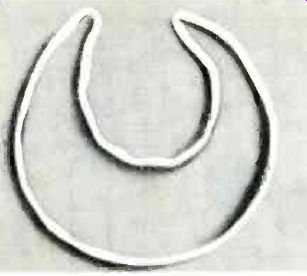
Fig. 2. Transmitting coil has been shaped to form L1 and L2.
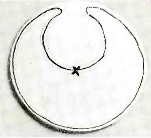
Fig. 3. Positions of L1 and L2 are marked on a plywood disc.
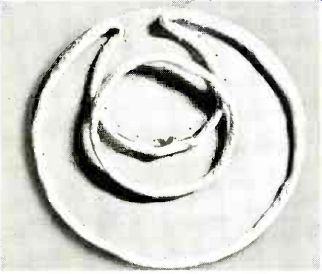
Fig. 4. The disc is shown with L1 and L2 tied in place and L3 on top
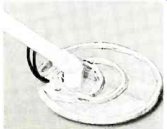
Fig. 5. The search-coil assembly with handle in place.
Construction. Procure a circular form 9 1/2" in diameter on which you can wind the transmitting coil. In assembling the prototype, a hamper lid was used, but a mixing bowl or cardboard cylinder would be suitable.
Wind a layer of masking tape 3/4-inch wide around the form so that the adhesive side is exposed. The tape will hold the wire and make winding the coil much easier. Wind a total of 175 turns of No. 30 enameled copper wire around the form, keeping the wire as close to the center of the tape as possible. The last turn should exit the coil at a point on the circumference 10 inches before the starting point is reached. Fold the tape around the coil and remove it from the form. Spiral-wrap the coil tightly with masking tape. Then shape the coil assembly as shown in Fig. 2 to form the transmitting coil. (LI is the large-diameter portion and L2 is the small-diameter section.) The coils must be shielded so spiral wrap them (starting with LI opposite the lead wires) with 1" wide strips of aluminum foil. Cover the coils completely except for a 1/4" gap between start and finish of the foil layer. Strip a 6" piece of hookup wire and lay it on the foil so that 2" exits next to one of the lead wires. Then spiral wrap the coils tightly with masking tape, covering the foil completely.
Next, cut a disc seven inches in diameter from a sheet of 1/4-inch plywood. Lay the shaped coil assembly on the disc and trace pencil lines around the inside of L1 and both sides of L2 (see Fig. 3). Remove the coir assembly and drill a series of 1/16-inch holes spaced 1/2 inch apart along the pencil lines. Then place the shaped coil assembly back on the disc and tie it down with monofilament fishing line, looping the line through the series of holes.
Obtain a circular form 3 1/2 inches in diameter on which you can wind the receiving coil. In assembling the prototype, a glass ashtray was used, but a cardboard cylinder would also be acceptable. The form should have a slight taper to facilitate removal of the coil after it has been wound. Apply masking tape to the form as was done in winding the transmitting coil, and wind 550 turns of No. 38 enameled copper wire, keeping the windings as close to the center of the tape as possible. When the coil has been wound, fold the tape around the windings and remove the coil from the form. Spiral-wrap the coil tightly with masking tape. Wrap the coil with foil and another layer of tape as on L1 and L2 being sure to cover the foil completely. If the two foil shields are allowed to touch when the coils are positioned, the detector will not function.
Now assemble the circuit of the Coinshooter. In the construction of the prototype, a small (5 inches by 13/4 inches) perforated board and point-to-point wiring were used. Printed-circuit assembly techniques are also acceptable. Because the circuit operates at very low frequencies, parts layout is not especially critical. Use an IC socket or Molex Soldercons for IC1 rather than soldering the chip's pins directly to the circuit board.
Potentiometers R29 and R30 and the loudspeaker are not mounted on the board. Rather, they should be affixed to the enclosure housing the circuit board. Resistor RI can be soldered directly across the outer lugs of potentiometer R29. A total of four holes (two 3/8 inch in diameter spaced 2 inches apart, and two 1/4 inch in diameter spaced 1/2 inch above and below the larger holes) should be drilled in the bottom of the project enclosure so that two shielded cables can exit the enclosure and self-tapping screws can provide mechanical support. Additional holes might have to be drilled for circuit-board standoffs.
Prepare the inner conductor and shield at one end of each of two 48-inch lengths of single-conductor shielded cable. Color-code both ends of one of the cables with a dab of enamel paint or nail polish. Connect the shields of the prepared ends of both cables to circuit ground. The inner conductor of the color-coded cable should be connected to the node C1, C2, and collector of Q1; the inner conductor of the other cable should be connected to the node C4, CS. These cables should exit the enclosure housing the circuit board through the two 3/s-inch holes previously drilled through its bottom. Be sure to outfit these holes with grommets or similar bushings that prevent chafing of their outer plastic jackets and that provide strain relief.
When the circuit board has been assembled and mounted in the enclosure along with the other components, place the transmitting-coil assembly and the receiving coil on a desk or on the floor away from any metal. Prepare the free ends of the two shielded cables and tin their inner conductors and shields. Using clip leads, connect the color-coded cable's conductors to the transmitting coil, and the other cable's conductors to the receiving coil. Connect the coil shields to the outer cable conductors. Apply power to the circuit and connect an oscilloscope probe between Q3's collector and circuit ground.
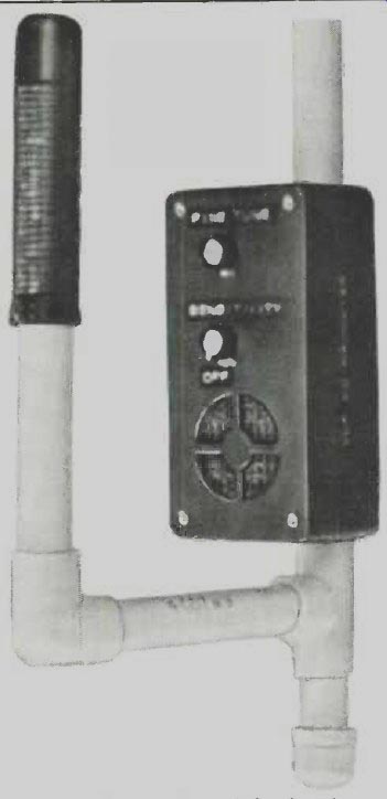
Fig. 6. The circuit-board enclosure is attached to the upper end of the
39-inch PVC pipe.
Referring to Fig. 4, position the receiving coil near the center of the plywood disc on which the transmitting coil has been mounted. Adjust the position of the receiving coil for the minimum signal level at the collector of Q3 as indicated by the scope beam's vertical deflection. Trace a pencil line on each side of the receiving coil after the null position has been determined, and then remove the receiving coil from the disc. Drill a series of 1/16-inch holes, spaced 1/2 inch apart, along the pencil lines. Reposition the receiving coil on the disc and tie it down with monofilament fishing line, looping the line through the small holes.
Using hot-melt or epoxy glue, cement a 13Y elbow PVC pipe joint in the area between L2 and L3 so that its open end points toward the gap in L1. (See Fig. 5.) Cut a 39-inch length of 1/2-inch O.D., schedule 125 PVC pipe, and drill four 1/4-inch holes in it, one above the other, approximately 2 inches in from each end. The two holes at one end of the pipe section should be 2 inches apart from each other, but the holes at the other end can be closer. Also drill two 1/8-inch holes spaced 1h inch above and below the two holes spaced 2 inches apart.
Slip the free ends of the shielded cables exiting the circuit-board enclosure through the 1/4-inch holes that are bracketed by the smaller holes and pass the cables through the pipe until they protrude from the far end. Run a bead of hot-melt or epoxy glue on the pipe and attach the bottom of the project enclosure to the pipe. Added mechanical support can be introduced by driving self-tapping screws through the two small holes in the bottom of the enclosure and into the matching holes that were drilled into the pipe section.
Feed the free ends of the shielded cables through the two holes at the other end of the pipe. Insert that end of the pipe into the elbow joint attached to the plywood disc so that the circuit enclosure faces away from the coil assembly. Then glue the pipe to the elbow joint using PVC cement, maintaining the orientation of the enclosure with respect to the coil assembly. (Note that PVC cement sets quickly.) Solder the conductors of the color-coded cable to the transmitting coil and the conductors of the other cable to the receiving coil. The polarities of these connections are unimportant. Connect the coil shield leads to the outer cable conductors. Insulate the solder joints using PVC electrical tape, silicone cement, or some other suitable material. Then cement the cables to the plywood disc in the area between L3 and the gap in LI using hot-melt or epoxy glue.
Cut 6- and 9-inch lengths of 1h-inch O.D., schedule 40 PVC pipe. Referring to Fig. 6, assemble a handle using the lengths of pipe, a 90` elbow PVC pipe joint, a tee PVC pipe joint, a bicycle steering-bar handgrip and PVC cement. The handgrip is glued to the 9-inch section of pipe, and one of the two collinear openings of the tee should be glued to the 39-inch pipe section to which the circuit-board enclosure and the search coil assembly are attached. PVC cement is fast-setting, so work quickly and orient the handle with respect to the circuit-board enclosure as it is in Fig. 6. The remaining end of the tee will be left open until the detector is balanced.
Apply power to the circuit and reconnect the oscilloscope probe between the collector of Q3 and circuit ground. Suspend the search coil in the air away from any metal and rotate the shaft of R29 to its minimum-sensitivity setting. Monitor the scope trace and, if necessary, slightly adjust the position of L3 so that a I-volt p-p signal appears at the collector of Q3.
Pass a pair of pliers approximately three inches under the search-coil assembly while monitoring the scope trace. If the signal level decreases, shift L3 through the null point and repeat the test. The signal must in-crease in amplitude when the pliers are brought near the search-coil assembly, or the detector will ignore coins and respond to the proximity of ferrous objects. Receiving coil L3 should be positioned as close to the null point as possible yet still provide an increase in signal amplitude when iron or steel is brought near the search-coil assembly.
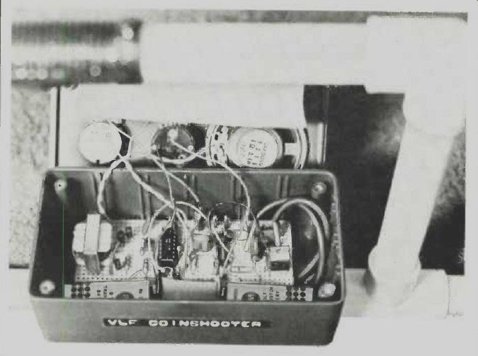
------------ Photograph shows the circuit-board enclosure mounted on
the PVC pipe The top has been unfastened and laid aside.
Next, pass a dime about three inches under the search coil and note the slight increase in signal level as displayed on the oscilloscope. Carefully fix the positions of the coils by bonding them to the plywood disc with quick-setting epoxy cement.
When the epoxy has cured, remove the scope probe and button up the circuit-board enclosure. Advance the setting of the SENSITIVITY control until the speaker begins to beep. Then adjust the FINE TUNE control to silence the speaker. Pass a pair of pliers three inches below the search coil and note that the speaker remains silent. Then pass a dime three inches under the coil and note that the speaker starts to beep. The most sensitive area of the search coil is near its center.
The search-coil assembly can be coated with two thin applications of resin to seal it, and then it can be painted white so that it matches the PVC pipe. The coils must be bonded securely to the disc before the application of sealant and paint. To minimize the possibility of displacing the coils, use spray-on resin and paint.
If the coils have shifted position before the resin has cured, a compensating piece of iron or steel can be added to the search-coil assembly. Determine whether this has in fact happened by removing the top of the circuit-board enclosure and reconnecting the oscilloscope probe between the collector of Q3 and circuit ground.
Pass a ferrous object three inches below the search coil and monitor the scope trace. If the proximity of iron or steel causes a decrease in signal level, position a small steel washer on or near receiving coil L3 to correct for the misalignment. Locate the required position by repeating the test for iron sensitivity and shifting the location of the washer until the correct response is obtained. Then fix the washer in place with epoxy cement.
Final Assembly and Use. Grasp the Coin shooter by its handgrip and check it for proper balance. The search-coil assembly should be parallel with and approximately 2 inches above the floor. Cut a 3-inch piece of 1/2-inch O.D., schedule 125 PVC pipe, and glue one end of it to a PVC pipe cap. Fill the pipe section with lead buckshot and tape its open end closed with PVC electrical tape. Then tape the shot-laden pipe section to the open end of the tee PVC pipe joint and recheck the balance of the project.
If it is unbalanced, un-tape the shot-laden pipe section, remove a little shot, tape the section closed again and reattach it to the tee PVC pipe joint.
Recheck the balance of the Coin-shooter. If necessary, repeat this procedure until the Coinshooter is properly balanced and feels comfortable to the hand. When the correct amount of shot has been determined, remove the pipe section from the tee PVC pipe joint, seal the shot in the pipe section with epoxy, and cement the section to the tee after the epoxy has cured. This completes assembly.
Take the finished project outdoors and hold the search coil 4 to 6 inches above the ground. Apply power to the project and adjust its controls so that the speaker emits a slow series of beeps. Lower the search coil until it is approximately 2 inches above the ground. The beeping should stop. This occurs because most soil is mineralized and affects the Coinshooter much like ferrous objects do.
The detector is now at maximum sensitivity and will detect coins at depths of from 1 to 3 inches, depending on their sizes and positions. Ferrous objects will not trigger the circuit unless they are very large or very close to the search coil or both. The Coin-shooter will detect aluminum cans, caps and pull tabs, but it responds best to coins. Raise the search coil from time to time to check for the slow beeps that indicate maximum detector sensitivity. Although the circuit is very stable, the FINE TUNE control might have to be adjusted occasionally to compensate for changes in ground mineralization, temperature, and, if an unregulated power supply is used, battery voltage.
Always hold the Coinshooter so that the search-coil assembly is 1 to 2 inches above and parallel to the ground. Try to keep the search coil at a constant height above the ground.
Swing the loop back and forth in front of you, making overlapping arcs. It is best to search slowly, but a coin will usually be detected even if the search coil passes over it quickly. For best results, operate the circuit as close to its switching threshold as possible.
When an object has been detected, move the search-coil assembly over it from front to back and from side to side to pinpoint its location. Keep in mind that the center of the search-coil assembly is its most sensitive point.
Probe for the object with a small screwdriver or similar digging tool. If you search for coins in parks and woodlands, do so without disturbing the landscape. Always fill any holes that you make with your digging tool and place any turf that has been disturbed back in its original position.
Source: Computers and Electronics--Experimenter's Handbook (1984)
Also see:
Build ‘LIDITH' -- A 3½-Digit Digital Thermometer
Build a Diode Temperature Probe
The Optimized Graphic Equalizer