
Inductance
Chokes of this type are generally required for one of two purposes: (1) Smoothing, and (2) Coupling. In either case, the inductance necessary is based on the impedance which it will have at a certain frequency. For smoothing, this frequency is that of the ripple to be eliminated in smoothing, and for coupling chokes it is the lowest frequency required to be reproduced.
The reactance of an inductance is given by the formula: XL= 2 pi fL, where pi is 3.14, f is the frequency and L the inductance in Henries.
For a smoothing circuit, the condenser reactance must also be known. and this is given by the formula:
1,000,000 Xc = 2 pi fC
where C is the capacity in Microfarads.
If a smoothing circuit is required to reduce the ripple voltage to 1/40th of that across the reservoir condenser, then the required ratio of reactance of smoothing choke and condenser will be given by: Xc I XL 40
Assuming an 8 mfd. electrolytic condenser is to be used, then its reactance to a ripple voltage of 100 cycles (the predominant frequency from a 50 cycle full wave rectifier) will be 1,000,000 2 X 3.14 x 100 X 8 = 200 ohms approx.
Therefore, the reactance of the choke must be 40 X 200 or 8,000 ohms. From the formula, 8,000 = 2,100L, therefore 8,000 L = - nearly 13 Henries.
2 x 3.14 x 100
In the same way, the inductance can he calculated for any given degree of smoothing.
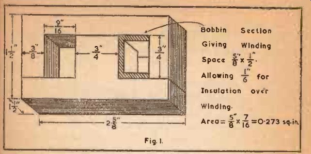
Fig. 1.
For a coupling circuit, the inductance must have a given reactance at the lowest frequency to be reproduced (usually taken as 50 cycles for good reproduction, although other values may sometimes be desired, see SECTIONs 2 and 5). This reactance is usually taken as equal to the valve (tube)'s anode load impedance.
Thus, if a valve (tube) has an optimum load impedance of 10,000 ohms, and is required to handle down to 50 cycles, the value of inductance required in a coupling choke will be 10,000 L = - 32 Henries approx.
2 x 3.14 X 50
These values of inductance must not be regarded as obtainable to great accuracy, as the actual value for any given applied A.C. voltage is dependent on the D.C. current flowing at the time, and on the amplitude of the A.C. voltage. Because of this fact, it is always good to allow a little in hand, so that performance will not vary too much if operating should change, due to changes in mains voltage. It would be well to design the chokes in the above examples to have inductances of, say, 15 and 40 Henries respectively.
Current and Volt Drop
The direct current to be carried by the choke will be fixed by other considerations. In the case of the smoothing choke, by the total current to be taken by the set, and in the case of the coupling choke by the anode current of the valve (tube). As well as being required to give the required inductance at this current, there will usually be an additional requirement that the choke shall not drop more than a certain voltage D.C. across it, due to its resistance.
We now have three factors, which roughly determine how large the choke must be physically. These three factors and the size do not have some simple relation, such as that the size of the choke in, say, cubic inches, is equal to the inductance x current x volt drop. For this reason, Tables 1-5 have been prepared to give a quick means of finding a suitable design.
Choice of Stampings
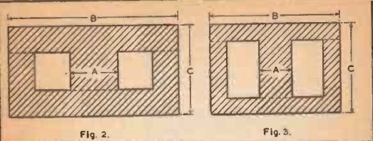
Fig. 2.
Fig. 3.
There are available from different manufacturers, hundreds of different shapes and sizes of laminations which could be used for chokes. Some arc definitely wasteful to use, as they would require a heavier or more bulky design to meet certain requirements. The shapes shown in Figs. 2, 3 and 4 are good shapes to use from the viewpoint of obtaining any required values of inductance, current and volt drop in the smallest or lightest possible design. The shape at Fig. 5 is that known as the "waste-free" (for further details, see SECTION 5). This is also a good shape, especially in the larger sizes, and has the additional advantage that it is often cheaper than other shapes. In the smaller sizes, the disadvantage is that much of the winding space is taken up by the bobbin, due to the shape of the "window".
There is another factor which may influence the choice of laminations. If there is to be a large A.C. voltage across the choke (such as there is in a choke for use between the rectifier and reservoir condenser), then with some designs there will be a loss of inductance due to the fact that the iron core will be saturated with A.C., over and above the effect due to the D.C. A good design for such a case employs a shape such as that at Fig. 2 or 5, and preferably a fairly large stack, or thickness, of laminations (i.e., if there should be a choice between, say, a 1" stack of one size, or a larger stack of a smaller size, then the latter would give best results).
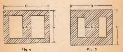
Fig. 4
Fig. 5
Use of Tables 1-5 The first table gives a range of 36 different designs, all of which can he wound using a 1-1" stack of laminations as shown at Fig. 1, allowing for a bobbin made of material 1/16th" thick. There are six different values of inductance given for each of six different values of direct current flowing. These necessitate a number of different windings, of which the turns and resistance are shown in the table.
The D.C. Volt Drop is also tabulated for convenience.
If the value should be outside the range covered by the 36 given, then it may be obtained with the aid of the factors at the bottom of the table. Two examples will best illustrate the use of these factors: Example 1.
An inductance of 200 Henries at 5 milliamps is required. In the table is shown a value of 20 Henries at 50 milliamps. The factors at the bottom show that if the inductance is multiplied by 10 (bottom line), then the resistance and volt drop will each be multiplied by 32, and the turns required by 5.6. Thus, an inductance of 200 Henries at 50 milliamps will have a resistance of 250 x 32 ohms, or 8.000 ohms, giving a volt drop of 12.5 x 32. or 400 volts, and requiring 3.600 x 5.6, or 20,000 turns. approx. Now, from the previous line, it is shown that if the current is divided by 10, then the resistance is divided by 10, an the volt drop by 100, the turns required being divided by 3.2. So the inductance originally required, of 200 Henries at 5 milliamps, will have a resistance of 8,000 ± 10, or 800 ohms, giving a volt drop of 400 ÷ 100. or 4 volts, and requiring 20,000 ± 3.2, or about 6.300 turns.
Example 2.
To design an inductance of 1 Henry at 1 amp on this core size:
In the table an inductance of 100 Henries at 10 milliamps is given as having a resistance of 550 ohms and requiring 5,300 turns. 1 amp. is 1,000 milliamps. or 100 x 10 mA. From the factor given. if the current is multiplied by 10, then the resistance will be 10 times, using 3.2 times the turns. So, if the current is multiplied by 100, then the resistance will be 100 times, and the turns will need to be 3.2 X 3.2. or 10 times. As the inductance is to be divided by 100, the resistance due to this change will he divided by 32 x 32. or 1,000, and the turns required will be divided by 5.6 x 5.6, or 32. Thus, the values given in the table for 100 Henries at 10 milliamps can be converted into those for 1 Henry at 1 amp. as follows: -
100 Resistance = 550 x 1 000 10.000
Volt Drop = 5.5 x = 55 volts 1.000 10
Turns = 5,300 x -= 1,650.
32 = 55 ohms.
Thus, it is seen that the table can he used to find the necessary value of resistance and turns to give any inductance and direct current on this core size. If the resistance and volt drop are of a suitable value. then this size could be used, if laminations are available, and when the coil is wound, it is necessary to find the air gap required from the tables in SECTION 4.
If the resistance or volt drop obtained in this way is either (1) unnecessarily low, or (2) too high, then an appropriate core size may now be chosen directly from reference to one of Tables 2-5, which list a variety of shapes, sizes and stacks, together with a factor showing the relation between resistance and turns for a design on this size as compared to that having the same inductance at the same D.C. on the size shown in Fig. 1, and tabulated in Table 1.
It will be realized that it is unimportant whether the laminations take the form of E's and l's, or of T's and U's, so long as they fit together to make approximately the shape shown. If a stamping is available which does not fit all the dimensions shown, the best method is to see which shape it most nearly resembles. This can readily be found by holding a lamination in one hand and this book in the other, and by holding them at different distances from the eye so that the outline of the lamination and the figure in the hook appear the same size. It will then be easy to see which of the four shapes given most closely correspond to the actual stamping.
To find the stack required, use the resistance factor column to find what stack of the given shape whose dimensions B and C most closely correspond with the actual stack which is required. Then, to find the turns factor, use the size whose dimension A is the same as the actual stamping, and of the same stack as nearly as possible.
Generally it will be seen that when the shape which is nearest to the actual is found, the size as judged by the nearest correspondence of dimensions B and C will also give the right value for dimension A.
Example 3.
Continuing the case of the 200 Henry 5 milliamp inductance of Example 1, suppose that a 4 volt drop is unnecessarily low. Assume that a drop of 20-25 volts can be allowed. This means that the resistance and volt drop can be 5 or 6 times that of the design given on the size of Fig. 1. From Table 2 we find that a lamination of this shape, having overall dimensions 1" x 1 3/4 ", will give a design having a volt drop of 5.5 x 4, or 22 volts, using a 1" stack. Or a larger one of the same shape, having dimensions 1 1/4 " X 2 3/16th", and 5/8" stack, gives volt drop of 4.8 x 4, or nearly 20 volts. Using the shape of Fig. 3, from Table 3 we find a size having overall dimensions 2" x 1 1/2 " and stack 0.5 ", which gives the same drop. This would obviously be the most compact size for this particular design.
There is another alternative in Table 5, using a 1" stack of a lamination having outside dimensions 1 9/16th" x 11", and giving a volt drop of nearly 20. In each case the number of turns required is calculated by multiplying the factor in the Turns Factor column by the number obtained from Table 1, i.e. 6,300.
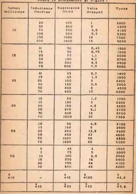
TABLE NO. 1. Values of Gunpoint and Inductance for Choke to Dimensions of
Fig. 1.
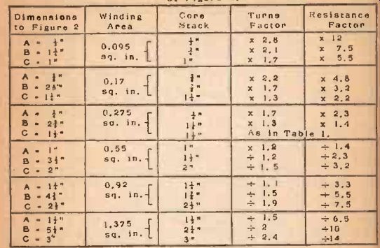
TABLE NO. 2. Values of Resistance and Turns compared to those in Table No.
1 for cores shapes as at Figure 2.
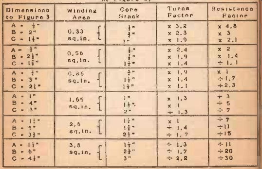
TABLE NO. 3 Values of Basis ante and Turns compared to those in Table No.
1 (or cores shaped as It Figure 3.
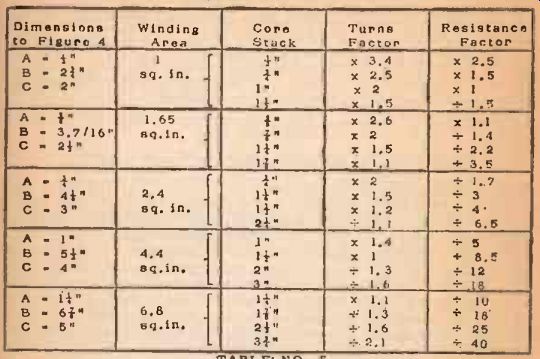
TABLE. NO. 4. Values of Resistance and Turns compared to those In Table
No. 1. for Cores shaped ns at Figure 4.
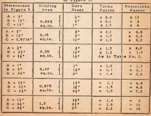
TABLE NO. 5, Values of Reels antes and Turns compared to those in Table
No. 1 for Cores shaped as at Figure 5.
Example 4.
Continuing the case of the 1 Henry 1 amp. choke of Example 2, suppose that 55 volts is much too great, and that a limit of 5 volts has been set. Then a size must be chosen which gives a division factor of 55/5 or 11. The largest size on Table 2 gives 14; there are two in Table 3 that give II, one in Table 4 that gives 12, and one in Table 5 that gives 11--a choice of five sizes. As this is a large-size choke, the best shape is the "waste-free", giving a 2k" stack of laminations 3.25" X 4.5". The turns required will be 1,650 / 1.9, or about 900.
For the method of finding wire gauge in these examples, see SECTION 10.
As well as the variation of inductance mentioned already as due to variation of current and A.C. voltage, the D.C. resistance cannot be expected to conform to close limits either, because of slight variations in wire gauge from the standard.