Primary Inductance and Resistance
Tables 1-5 may he used to find the inductance of any given number of turns on the sizes given, but the resistance calculated from these tables will be increased, and with it the volt drop.
Suppose that the primary consists of 3,000 turns on the fourth size listed in Table 3, i.e., a r stack of laminations with dimensions A = B = 2 ½; C = 1 7/8" (see Fig. 3), and that the primary current is 10 milliamps. From Table 3 we see that 3,000 turns is 2.4 times as many as would be required on the size given in Table 1 to have the same inductance at the same current. This means that 3,000 ÷ 2.4, or 1,250 turns would be required on this larger size. Now, referring to Table 1, at 10 milliamps there is no number of turns as low as 1,250, but the factor at the bottom for multiplying or dividing the inductance by 10 is 5.6. Multiplying 1,250 by 5.6 gives 7,000 turns, which does fall within the range given by the table. 5.300 turns give an inductance of 100 Henries at 10 mA., and 7,300 turns give an inductance of 150 Henries at 10 mA., so 7,000 turns will give an inductance of about 140 Henries at 10 mA. Now, dividing by 5.6. this means that 1.250 turns on this size, or 3,000 turns on the actual size. will give 14 Henries at 10 mA.
As a choke, the 7,000-turn winding would have a resistance of about 901 ohms (see Table I, between 550 and 1,000, for 5.300 and 7,300 turns respectively). By the factor at the bottom of Table the resistance of the 1.250 turns will he 900 32 = 28 ohms approx.
From the resistance factor in Table 3 for the actual size, the resistance of a choke having the 3,000 turns as specified would be 28 x 2 = 56 ohms. But, in this case. the primary will only occupy one-half or perhaps one-third of the total winding space. This means that its resistance will be increased by two or three times to 112 or 16g ohms. This. then. allows the remaining one-half to two-thirds of the space for the secondary. If a very high step-up is used, needing a very large number of turns on the secondary. then even less than one-third of the space may have to do for the primary.
Choice of Size.
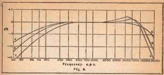
Fig. 6
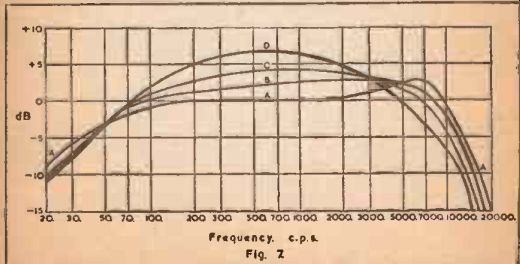
Fig. 7
Of the sizes shown in the tables, the one already mentioned is the best for an inter-valve (tube) transformer for direct coupling. It gives the greatest possible step-up in any given inter-valve (tube) circuit, consistent with a balanced frequency response. If a smaller size is used, then either step-up must be sacrificed or the frequency band will be higher up the scale, giving a "thin" quality reproduction. If a larger size is used, then again step-up must be reduced, or else the frequency band will be moved down the scale, giving a "woofy" reproduction.
Choice of Ratio and Turns.
The response curves shown in Figs. 6 and 7 show various shapes of the frequency response obtained with the ratios and turns given in Table 6. For all these curves, the design is taken as being for a transformer to work with a valve (tube) having an anode current of 10 milliamps, and an anode impedance (not the optimum anode load) of 7,000 ohms. This would be a typical medium slope triode.
In Fig. 6, the same ratio is achieved with three different numbers of turns. Curve AA is the result of using 4,000/12,000 turns; curve BB with 3,000/9,000; and curve CC with 2,000/6,000.
In Fig. 7, different turns ratios are used, having the same number of secondary turns, 12,000. Curve AAA is obtained as in Fig. 6, for a 3/1 using 4,000/12,000; curve B is for ratio of 4/1, using 3,000/12,000 urns: curve C for a ratio of 5/1. using 2,400/12,000 turns; and curve D for a ratio of 6/1, using 2,000/12,000 turns. In this case, it will be seen that increasing the ratio narrows the frequency band, but that it is kept balanced about a mid-frequency of about 600 or 700 cycles. For reproduction of music this is a good ideal.
To enable the information given in these curves to be applied to other cases when other types of valve (tube) may be used, the column "referred impedance" is given. This is simply the anode impedance of the valve (tube) multiplied by the square of the turns ratio. Any other transformer will have the same shape cut-off at the high frequency end of its response if it has the same number of secondary turns, and the same referred impedance as that given in the table. The shape of the cut-off at the low frequency end of the response depends upon the primary inductance and the anode impedance of the valve (tube), as stated in SECTION 1.
Example 5.
To estimate the best ratio and turns for use with a valve (tube) having an anode impedance of 2,500 ohms and an anode current of 20 milliamps.
The widest frequency range is obtained with the use of 12,000 turns on the secondary, and with a referred impedance of 63,000 ohms gives a response cut-off at the top end as shown in curves A (Figs. 6 and 7). To make 2,500 ohms refer as 63,000, the square of 63,000 the turns ratio must be or about 25/1. This gives a turns 2,500, ratio of 5/1. Then the primary turns will need to be 2,400. Using Tables 1 and 3, as before, this winding will have an inductance of about 6 Henries with 20 mA flowing. This makes the cut-off frequency at the low end that at which 6 Henries has a reactance of 2.501 ohms. XL = 2 pi fl, i.e., 2,500 = 2 X 3.14 x 6 x f. therefore,
f = 2.500 / 2 X 3.14 X 6 = 65 cycles, approx. This means that the point where the response is 3 dB down from level is at 65 cycles. Curve A shows this as 50 cycles.
Thus this case, using a 5/1 of 2,400/12,000 will give an L.F. response not quite so good as that in curves A, while the H.F. response will be identical. Using the same turns on the next size a -1" stack of the next larger laminations listed) will have the effect of bringing the whole response down by a ratio of about 5/6. This will about balance the frequency response.
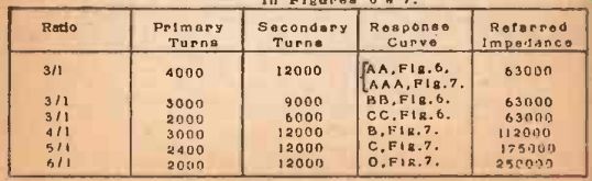
TABLE NO. 6. Conditions required for response curves in Figures 6 / 7.
Example 6.
To estimate the best arrangement to use with a valve (tube) having an anode impedance of 10,000 ohms, and an anode current of 5 mA.
Using the same reference impedance, the square of the ratio needs to be 63,000/10,000 or 6.3/1. This gives a turns ratio of about 2.5/1, and se the primary turns would be 4,800.
To work out the primary inductance, as before; 4,800 turns on the best size as already stated have the same inductance for the same current as 4,800 / 2.4. or 2,000 turns on the size of Fig. 1.
There is no section of Table 1 for 5 mA., but there is for 50 mA., and the factor at the bottom shows that multiplying or dividing current by 10, multiplies or divides turns by 3.2. So the same inductance with 50 mA. instead of 5 mA, would need 2,000 x 3.2, or 6.400 turns. This closely corresponds with the figure for 50 Henri, and the error introduced by assuming that 4,800 turns on our actual size will produce an inductance of 50 Henries at 5 mA, is quite small.
To find the 3 dB frequency: XL = 24L; 10,000 = 2 x 3.14 x f x 50.
10,000 or f = - 32 cycles.
This is rather better than 2 x 3.14 x 50 necessary. and it will be found that an inductance of 32 H will bring the 3 dB point to 50 cycles. Working back, we find this needs less than 4,000 turns on the actual primary, if 4,000 turns is used, the ratio is 3/1. and the referred impedance will be 9 x 10,000 = 90.000 ohms. This will give a H.F. cut off mid -way between that for curves A and B in Fig. 7, whilst maintaining the L.F. cut-off a little better than that for curve A. This will be reasonably well balanced, giving a range from about 45 to 10.000 cycles.
Method of Winding and Connection.
With any inter-valve (tube) transformer it is important to keep the winding capacities to the lowest possible figure, as these introduce further loss of high frequencies. The secondary, being the winding at the highest impedance, is the most important in this respect. For this reason the following method should he adopted:
The secondary should be wound on fiat, so as to have the smallest diameter, and the inside, or start, of the winding should be the end which is eventually connected to the grid of the next valve (tube).
This means that the outside, or finish, will be connected either to the grid bias or earth.
After insulation has been placed between windings, the primary will be wound on. This may be of the same or of different gauge from the secondary (see SECTION 10). The inside, or start, should be connected to H.T. supply or decoupling, While the outside, or finish of this winding should be connected to anode.
This practice will always be found to give the best results.