Turns and Impedance Ratio.
The purpose of this type of transformer is to match the impedance of a loudspeaker, or group of loudspeakers.. to the optimum load of the valve (tube). That is, the transformer has the effect of transforming the impedance of the speaker so that the impedance which it presents in the primary winding is equal to the optimum load of the output valve (tube).
It is well known that the impedance ratio of a transformer is equal to the square of the turns ratio. To assist in calculating one ratio from the other, a table giving numbers and their squares in reasonable steps is included in SECTION 10.
Impedance/Turns Relationship
This depends on the D.C. current flowing in the primary, on the size and shape, and on the lowest frequency required. To make calculation easier, if the actual D.C. current flowing in the primary is referred to a theoretical 1,000 ohms winding, then the turns for such a winding can readily be found, and from that the turns in the actual windings determined. Using this reference, the current in this winding will bear a relationship to the maximum output power which will vary very little, although widely different types of valve (tube) may be used.
Table 7 gives a series of reference figures. For each value of current referred to 1,000 ohm winding, is given two figures for the turns in a 1,000 ohm winding: one for general use. giving a low frequency cut-off of 50 cycles; and the other for special use when a circuit is used for speech only, giving a low frequency cut-off of 200 cycles. For each value of current is given an approximate figure of maximum output. This may be found useful if some of the valve (tube) data is not obtainable (e.g., the optimum load). For each value of current and cut-off is given the approximate percentage loss due to winding resistance.
Choice of Size.
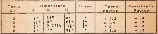
The figures in Table 7 are for the same core dimensions as those shown in Fig. 1. In practice, for an output transformer it will he better from the constructional viewpoint if the stack is less than twice the A dimension, preferably equal to it. The chief factor in determining size is the amount of power that can he allowed as loss in the transformer. The appropriate loss factors for other sizes may be found from the figures given by multiplying or dividing by the Resistance Factor given in Tables 2-5 for the appropriate shape and size.
Having chosen a suitable size, the number of turns for a 1,000 ohm winding can be found by use of the Turns Factor in the same table, applied to the value given in Table 7.
Example 7.
Calculate the turns required to match a 15 ohm speaker to a valve (tube) having an optimum load of 4,500 ohms, and an anode current of 48 milliamps for general use on music and speech. It should be at least 90% efficient.
If 48 milliamps are flowing in a winding of impedance 4,500 ohms, then the equivalent in a 1.000 ohms winding will be
48 x __ /4500/1000 = 100 mA. approx.
From this value in Table 7 it is 1,000 seen that on the size shown in Fig. 1, for a 50 cycle cut-off, 1,300 turns for 1,000 winding give a loss of 13%.
To have at least 90% efficiency, the loss must be at most 100 - 90 = 10%. This means that a size must be chosen with a dividing Resistance Factor of at least 1.3. The -following sizes satisfy this:
---------
It will be noticed that there is little difference in size, and therefore here is not much to choose as to which is the best to use. Assume that a size similar to the one from Table 3 is available, then the loss will be 13 1.7 = 7.6% and the efficiency 100 - 7.6 = 92.4%. The turns for a 1,000 ohm winding will be 1.4 X 1,300 = 1,800 approx. Then the turns for a 4,500 ohm
winding will be 3,800. The turns for the 15 ohm 1.000 15 winding will be = 220.
Thus the transformer will require a primary of 3,800 turns and a secondary of 220 turns.
Example 8.
The only details known about an output valve (tube) are that with 450 volts H.T. it should give about 12 watts output, taking an anode current of 120 milliamps. It is required to match a hem type speaker for use on speech only, with an efficiency of about 90%. The speech coil impedance is 4.5 ohms.
From Table 7 it is seen that 12 watts corresponds to a current referred to a 1,000 ohms winding of 200 mA. The actual current is 120 mA, so the optimum load must be 2,800 ohms.
Also the loss for a 200 cycle cut-off type on this size is only 4%. As the efficiency is only required to be 90%, the loss can be up to 10%. This means a smaller size can be used, which may facilitate fitting the transformer into the horn housing. Thus the resistance can be multiplied by 2.5 (but not more). It will be seen that a I" stack of the same lamination will give a resistance factor of x 2.3. An alternative is found in Table 5. using a 1" stack of a similar size. In either case the turns factor is X 1.7, so the calculation of turns in this case will be the same whichever is chosen.
From Table 7 the turns for a 1,000 winding are 650. So for this size the turns will be 1.7 x 650 = 1.100. The turns for a 2,800 ohms
winding will be 1.850. The turns for the 4.5 ohm 1,000
winding will be 74. The ratio in this case is 2,800
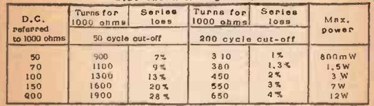
TABLE NO, 7. Impedance/Turns Relationship for Coro of Size shown in Figure
1.
Special Precaution for 200 Cycle Cut-off.
When an amplifier is to be used under conditions required to operate a loudspeaker having a 200 cycle cut-off (i.e., a horn type).
there are two precautions necessary: (1) To see that no signal or any considerable amplitude reaches the speaker. This is to prevent damage to the speaker itself, or the introduction of distortion by it.
due to receiving frequencies which it is not designed to handle (2) To see that no signal of a lower frequency which may be present in the amplifier causes distortion to frequencies which do reach the loud speaker.
This second requirement means either that the output of the amplifier must be correctly matched at these frequencies although arrangement is made so that they do not reach the speaker. or that arrangement must be made to ensure that these frequencies do not reach the output stage of the amplifier.
SECTION 5 shows a way in which matching can be maintained with a push-pull stage output by means of a series condenser, but this is not applicable to the cases considered in this section. It is therefore necessary, when using a 200 cycle cut-off type, to take steps to ensure that there is a similar cut-off in the amplifier, somewhere before the output stage. This should take the form of a coupling condenser whose impedance at 200 cycles is equal to that of the grid leak following it.