With each of the types of component considered in SECTIONs 1-3 there is D.C. flowing in one of the windings which has a tendency to saturate the iron core. For this reason an air gap is employed, instead of laminating the transformers in the manner required for types considered in SECTIONs 5-7.
For any given case. too small an air gap will result in the magnetic flux due to the D.C. component producing saturation, while too large a gap will cause loss of inductance because of the magnetizing current necessary to drive the A.C. component of flux across the air gap.
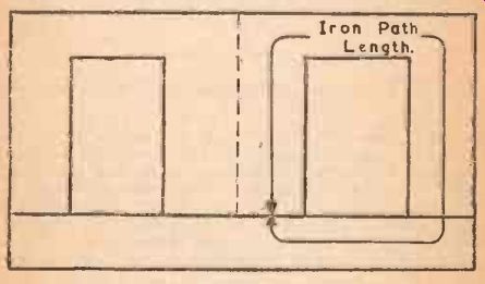
Fig. 8
The chief factor which determines the best air gap for any given example is the total effective D.C. magnetizing force, which may be expressed in ampere-turns-that is to say, the current in amperes multiplied by the turns in the winding. The type of transformer iron used, and the length of iron path (see Fig. 8), both have a slight effect upon the best gap, and on the resulting inductance. As the effect of different iron is so slight, the use of more expensive irons is not considered worth the extra cost in general, so the only iron considered here is ordinary grade transformer iron (usual lamination thickness about 0.016").
All the figures in SECTIONs 1-3 for Current and Inductance assume that the air gap is adjusted to the best size. Table 8 gives the approximate gap lengths for different values of ampere turns. Only two values of length of iron path are shown, as this has so little effect, and so practical values will fall between those shown, which are respectively smaller and greater than all the sizes of lamination listed in Tables 2-5. The length of air gap given is half the total required air gap, because generally, with either T and U, or E and I type laminations, there will be two gaps in the iron circuit. If a type is used which only utilizes one gap in the iron circuit, then twice the figure given in Table 8 should be taken.
The gaps listed include very small values, which can in practice only be obtained by squeezing the two sections of laminations together without any gap spacing material. For larger gaps, pieces of insulating material of the required thickness may be inserted in the gaps to maintain uniform spacing of the whole cross section of the core.
If equipment is available to test the component for inductance under operating value of D.C. current (as outlined in SECTION 9), then the values given in Table 8 will give a good starting point, which will usually be found within a close percentage of the actual optimum. Deviations will generally be due to practical variations on account of difficulties in clamping up. If such equipment is not available, then care should be taken to produce as near to the specified gap as is possible. making slight allowances if the edges of the laminations should have been slightly burred in stamping.
To give examples of the use of this table, and to complete the examples given in previous sections, those numbered 1-8 arc listed opposite. with a repetition of current flowing and turns:
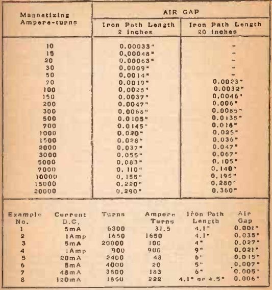
TABLE NO. 8. Air Gaps for Components Carrying D.C.