Choice of Size.
For this purpose the best shape is that known as the "Waste-free". The dimensions are set out in Fig. 9, referred to the width of the center limb. The small diagram shows the way the laminations are stamped from the sheet so there is no waste portion. It will be seen that this method of cutting can only be employed to make laminations of the E and I type. However, from the point of view of efficiency, frequency band, etc., it is obvious that a core of the same shape constructed from laminations of the T and U type will be equally good.
Table 9 gives data for a series of easily obtainable sizes, in different stacks. It shows the turns for a 1,000 winding which give a transformer of maximum efficiency at a frequency of 400-1,000 cycles. The section headed "Maximum power. Watts", shows the maximum power that can be handled by the transformer under this condition at two frequencies, 50 c and 200 c, without introducing serious distortion. The figures in the 50 c column in brackets are so shown because they cannot he applied at that frequency under maximum mid-band efficiency condition, because they are below cut-off, and hence the inductive load on the output valve (tube) would introduce distortion by mismatching. However, if appropriate factors from Table 10 are used to reduce cut-off to 50 cycles or below, the corresponding factors from the same table may be used to obtain the maximum output at 50 cycles in conjunction with the figures in brackets.
Table 10 shows how increased power and a lower cut-off frequency may be obtained when the impedance/turns relationship is increased above the figure given for any size in Table 9, together with the increases in losses, from which may be deduced the efficiency obtainable.
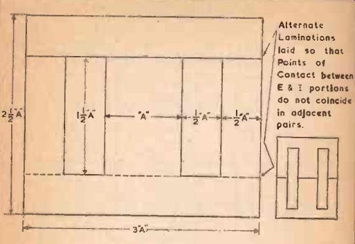
Fig . 9---Alternate Laminations laid so that Points of Contact between E & I
portions do not coincide n adjacent pairs.
The factors at the bottom of Table 10 show how the figures can be improved by the use of Radiometal laminations instead of standard transformer iron.
For designs of both Class A Push-Pull Output and Loudspeaker matching transformers. the total winding space occupied by the primary winding should be approximately equal to that occupied by the secondary.
For any type of Q.P.P. output stage, the most efficient disposition of winding space is when each half of the primary occupies about 30% of the space, and the secondary occupies 40%. Under this condition the figures given by Tables 9 and 10 have to be modified slightly. For maximum efficiency at mid band, ohms should be divided by 1.1, the maximum power in watts figure reduced by 1.2, and the mid band losses increased by 1.2. The L.F. cut-off frequency will also be multiplied by 1.2.
200 Cycle Cut-off Matching.
With push-pull type outputs the author does not recommend the incorporation of 200 cycles cut-off in the output transformer. If it should be regarded as essential to do so in order to save space, then the precaution mentioned in Section 3 must be observed. A preferable method is to incorporate the bass cut between the output transformer and the matching transformer by means of a series condenser, which should be chosen so that its reactance at the cut off frequency is equal to the load impedance referred to that point.
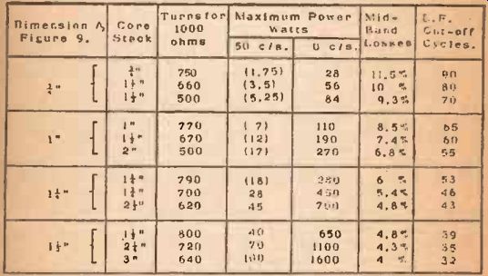
Table NO. 9 Power, and L. F, Out -Off for Maximum Efficiency at Mid-Rand
Condition
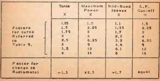
Table. NO. 10. Factors for other impedance/turns relationships, and for
change from standard transformer Iron to Rad 'emote!
Methods of Winding and Connection.
Fur the smaller size push-pull output transformers, the best method of winding to preserve a good balance at the higher frequencies is to wind one half of the primary before, and the other half after, the secondary. The two ends of these two windings which are adjacent to the secondary are then connected together to form the center tap. This method is shown diagramatically at Fig. 10a.
For larger sizes, and especially those intended for Q.P.P. type output circuits, closer coupling of the windings may be considered necessary. The method of winding and connection shown at Fig. 10b has been proved to give very accurate balance indeed at the high frequencies. Some authorities recommend complicated arrangements using a divided bobbin, so as to maintain geometrical symmetry.
The arrangement here shown maintains just as good electrical symmetry, with a far simpler winding arrangement, and gives a wider frequency response band for a given size and complexity of design. The secondaries are shown as two windings connected in parallel. This arrangement preserves the best balance, especially if secondary has a fairly high impedance. If the secondary impedance is quite low compared to the primary, then a series arrangement will serve equally well, when the junction can be used as a center tap, and earthed.
For loudspeaker matching transformers, a simple arrangement with the primary and secondary (each in only one section) is adequate.
It is not important in this case which winding is nearest to the core, so the order of winding may be determined by convenience from the point of view of the particular wire gauges to be used.
Example 9.
A push-pull amplifier giving an output of 10 watts, with an anode to anode load of 4,000 ohms, requires an output transformer with an efficiency of about 90% to match it to a 10 ohm speaker for music and speech.
A 1" stack of 1" waste -free laminations operating at maximum mid -band efficiency has 8.5% losses and a cut-off of 65 cycles. If the turns are multiplied by 1.25, then the mid-band losses become 1.1 x 8.5 = 9.5% (or an efficiency of 90.5%), and the cut-off becomes 65 + 1.5 = 43 cycles. Thus the maximum output at 50 cycles can now be 1.5 x 7 =10.5 watts winding for 4,000 ohms will require a total of 1920. The turns for a 1,000 winding 1.000 will need to be 1.25 x 770 = 960. A turns and a winding for 10 ohms will require 96 turns. Thus the winding 1,000 will be:
1. Half Primary, 960 turns.
2. Secondary, 96 turns
3. Half Primary, 960 turns.
Example 10.
A large amplifier, having an output of 40 watts, has an anode to anode load figure of 8,000 ohms, and requires to be matched to 250 ohms for speaker distribution. Give appropriate designs in standard transformer iron and in Radiometal, for use on music and speech. efficiency to he 95%.
Using standard transformer iron: Either a 2.5” stack of 1.5" waste -free, or a 1.5" stack of If" waste -free will satisfy the required conditions without modification. Each gives an efficiency of 95.2%.
Using Radiometal: A 1" stack of 1" waste-free gives a mid-hand loss of 8.5 1.7 = 5%. Under this condition the cut-off frequency is 65 cycles, and maximum output without distortion would only be 7 x 2.3 = 16 watts. A 1 t" stack of 1" waste -free gives, under maximum mid-band efficiency, a loss of 7.4 ÷ 1.7 = 4.35%, a cut-off of 60 cycles, and a maximum output of 12 x 2.3 = 27.6 watts. Increasing the turns by 1.25, the maximum power is increased to 1.5 x 27.6 = 41 watts, the mid -band losses become 4.35 x 1.1 = 4.8%, and the L.F. cut-off will be 60 1.5 = 40 cycles.
Thus it is seen that a 1.5 " stack of 1" waste-free Radiometal will give almost identical performance with that of either a 2.5" stack of 1.25 ", or a 1.25 " stack of 1.5" in standard transformer iron. This results in a reduction of outside dimensions from 3.25" x 4.5" to 2.5" x 3".
To complete the design on Radiometal: The turns for a 1,000 ohm winding will be 670 1.3 x 1.25 = 640 approx. Thus the primary will require a total of 1,800 turns and the secondary turns will be 320.
Thus, following the 1,000 winding arrangement of Fig. 101% the required sections are:
1, Quarter Primary, 450 turns; 2, Secondary, 320 turns; 3, Half Primary, 900 turns; 4, Secondary, 320 turns; 5, Quarter Primary, 450 turns.
Example 11.
A cabinet type speaker with a speech coil impedance of 15 ohms is required to take one -eighth of the power from Example 10.
Efficiency to be not less than 80%.
One-eighth of the power is 40/8 = 5 watts. The primary impedance must be 8 x 250 = 2,000 ohms. Using a f" stack of 1" waste -free, with 1.75 times the turns from Table 9. the maximum power is 3 x 1.75 = 5.25, the mid-band losses are 1.7 x 11.5 = 19.5%, and a L.F. cut-off of 90 3 = 30 cycles. This satisfies the conditions. Then the turns required are:
1. Primary 1850 turns.
2. Secondary 160 turns.
Example 12.
A horn type speaker, speech coil impedance 5 ohms. is required to take one -quarter of the power from the same amplifier, with a 200 cycle bass -cut. What condenser is required. and what will be the efficiency, using the same size transformer as Example 11? Using maximum mid-band efficiency, this size can handle 28 watts at 200 cycles, with losses of 11.5%, giving an efficiency of 88.5%. The primary impedance will be 4 x 250 or 1,A00 ohms.
Thus the condenser must have an impedance of 1,000 ohms at 200 cycles:
C= 0.8 MF. Turns required as follows:
1. Primary, 750 turns.
2. Secondary, 53 turns.