A POWER SUPPLY IS a circuit which provides the operating voltages for the other circuits in a piece of electronic equipment. Except for heater current for tubes, all operating voltages are DC. While small radios can obtain all their requirements from batteries, most electronic equipment plugs into the 117-volt power line.
This does not mean that all power supplies convert AC to DC, but the majority do. In their circuitry they are similar to the AM demodulation circuits described in section 6. There are also independent power supplies, portable or otherwise, which are not part of some other piece of equipment.
BATTERY POWER SUPPLY
The simplest and one of the most widely used sources of power for electronic equipment is a battery. The same symbol is used, regardless of type. The long line is always positive, but polarity may be indicated in addition, as in Figure 7.1. Sometimes a distinction is made between single cell and multi-cell batteries, symbolizing the first by a single pair of lines, one short and one long, although this may be used also to
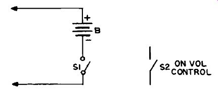
Figure 7.1 Battery Power Supply indicate only a generalized direct-current
source. Voltage value may also be shown.
Switches are usually shown as S1 or S2, in Figure 7.1. S1 seems to be more popular. They are usually shown open. (S2 could not be shown any other way!) Battery power supplies seldom have any other components, unless they are rechargeable-battery supplies. These have a simple rectifier type supply as, for example, that illustrated in Figure 7.7. (L1 will probably be a resistor, however.) On most radio and TV receivers the physical switch is mounted on the rear of the volume control, and is turned on or of! by the same knob. This may be indicated in a schematic by a statement beside the switch symbol (as by S2 in Figure 7.1), or by a dashed line connecting the switch symbol to the variable resistor symbol to indicate they are ganged together. In this way the two symbols can be located according to their functions.
UNIVERSAL AC-DC POWER SUPPLY
This power supply got its name because it could be operated from both AC and DC power lines, as it does not use a transformer. You are not likely to encounter a DC power line today, but the name is sup posed to sound better than " transformerless power supply." Figure 7.2 gives a typical example.
Distinguishing Features
1. Rectifier (diode) tube, or solid-state rectifier.
2. Pi-filter, in which R1 may be replaced by a choke.
3. Series-string of filaments across the power line, as shown.
4. No power transformer.
5. Connection to power line, and on-off switch.
Detailed Analysis
In this supply the tube heaters are connected in series across the power line, which is assumed to be at 120 volts. As you know, the first figure, or figures, of tube numbers give the heater voltage required.
Those shown in the diagram add up to 121 volts.
Five tubes, each requiring 24 volts, would also add up to 120 volts.
However, when this circuit was adopted heater voltages had already been pretty well standardized at 6.3 or 12.6 volts, which were the battery voltages originally used. Furthermore, using higher AC voltages for heaters introduces hum when the heater current is AC. Consequently the lower-voltage tubes already available were used in the circuits most susceptible to hum pickup, and two special tubes were developed for the less sensitive audio output and power supply circuits.
By arranging them so that the most sensitive circuits' tubes are also at the low end of the string (lowest AC voltages), hum pickup has been kept below an audible level.
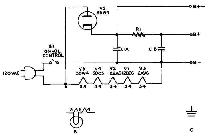
Figure 7.2 Universal AC-DC Power Supply.
The numbers 3 and 4 indicate the tube pins for the heaters. By showing the heaters separately in the power supply like this, it saves showing them in the tube symbols, and avoids the additional congestion and confusion of having to draw heater connections running all over the schematic.
The AC of the power line is converted to DC by the rectifier tube V5. When the side of the power line connected to the plate swings positive the other side swings negative and supplies electrons via SI to the low side of the circuit, B-. Current lows from B- to the cathodes of the four tubes in the radio, from the cathodes to the plates and screen grids, and back to B+ and B+. From these points it reaches the cathode of V5, lows to the plate, and from there to the positive side of the power line.
When the AC line reverses polarity on the alternate half-cycle, V5's plate becomes negative with respect to the cathode, and V5 cannot conduct. Consequently, bursts of current low through V5 in one direction only on the half-cycles that make its plate positive, but no current lows on the alternate half-cycles; hence it is called a half-wave rectifier, which means that half the power available from the power line is not being used. For the small power requirements of this type of radio this is not important.
These pulses of DC cannot be used for most of the tubes, as they would still create a loud hum, so a pi-filter circuit is provided to smooth them out and give a constant voltage at B+. The filter consists of C1 A and C1B, which are two sections of a dual electrolytic capacitor (usually from 30 to 50 microfarads each), and R1, a resistor capable of handling the plate supply current of V1, V2 and V3. Its value will probably be around 1000 ohms.
Filters are covered more fully in section 8. Without going into too much theory we can say that in this one, when V5 conducts, C1A charges up to the voltage at V5's plate, since the tube has a low resistance when conducting. When V5 cuts off it cannot conduct, so C1 A starts to discharge through R1 and the rest of the circuit. The circuit resistance is much higher, of course, so C1A has not discharged very much before V5 starts conducting again on the next positive half-cycle and replaces whatever was lost. The voltage on C1A therefore fluctuates between the maximum value and that to which it falls when V5 is not conducting.
This fluctuating voltage can be thought of as consisting of two components: a steady DC voltage at the lower value, and an AC voltage ripple " riding" on it. This AC component is still too much for our B+, so R1 and C1B are provided as a voltage divider to reduce it to an acceptable figure. For AC at 60 hertz, C1B has a reactance of 100 ohms or less, whereas R1 is at 1000 ohms (or thereabouts). This divides the AC voltage appearing between R1 and C IB by a factor of at least eleven. However, as C1B offers a very high resistance to DC the latter is hardly affected at all. For small loads this amount of filtering is quite adequate.
The one tube that draws a heavier plate current than the rest (V4) is supplied directly from C1 A (B+ supply). As this tube is an audio power amplifier, fluctuations in the plate voltage have very little effect on it (see section 3), and the ripple on its supply is therefore of no consequence.
Circuit Variations
As you just saw, resistor R1 is perfectly adequate as part of the pi-filter as long as the amount of current required is small (and when the plate supply of V4 is drawn directly from C1A). Therefore, in small and inexpensive clock radios and the like this will be the normal arrangement. However, as soon as a higher current requirement arises, as in a set with more tubes, or with pretensions to high fidelity, then a choke will be substituted for R1. A 5-henry choke presents a reactance of approximately 2000 ohms to the AC component, while offering negligible resistance to the DC component. As a result higher DC currents can be passed without dropping the voltage. For AC the effect is the same as when a resistor is used. You might meet this type of filter more in TV sets today, as we shall see later on in this section.
A pilot light is sometimes connected across half of V5's heater filament, as shown at B. This not only tells you that the set is on, but also acts as a safety device. The plate of V5 is connected to the centertap of the filament (pin 6) instead of to point A (in the main diagram).
If a short develops somewhere in the set so that a heavy current is drawn through V5, the half of the filament between pins 3 and 6, and the pilot light, will burn out as if they were a fuse.
A ground symbol (as at C) is frequently drawn at B- to indicate a chassis ground return. This saves drawing in the low side of the circuit. The same symbol is then used at other points in the set to indicate points also connected to the chassis, and therefore to B-.
This has become such a habit with radio and television manufacturers and others that they do it even though there may be no real chassis (as in today's printed-circuit boards). It has a distinct advantage in small crowded diagrams, but in the much larger prints used in industrial work it is more usual to draw in the "ground return" or low side of the circuit.
A disadvantage of the AC-DC power supply was that drawing a heavy current from it would cause the voltage on C1A to fall excessively between the half-cycles when V5 conducted. While this could be overcome by elaborate filtering it is more economical to charge the input filter capacitor on both half-cycles. Full-wave rectifiers which do this are shown in Figures 7.3 and 7.4.
Distinguishing Features
This type of power supply uses a power transformer with various windings. Diodes are connected to the opposite ends of the secondary winding or windings used for the DC supply. In vacuum-tube types the diodes may be in one tube (as in Figure 7.3), or in separate tubes (more usual for higher voltage supplies).
Input connections from the power line are indicated by illustrating a plug or similar connection, switch, fuse, line filter, all on the primary side of the transformer.
The output is via a filter and voltage divider network. There may be more than one supply, as in Figure 7.4.
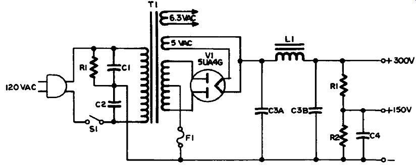
Figure 7.3 Vacuum-Tube Full-W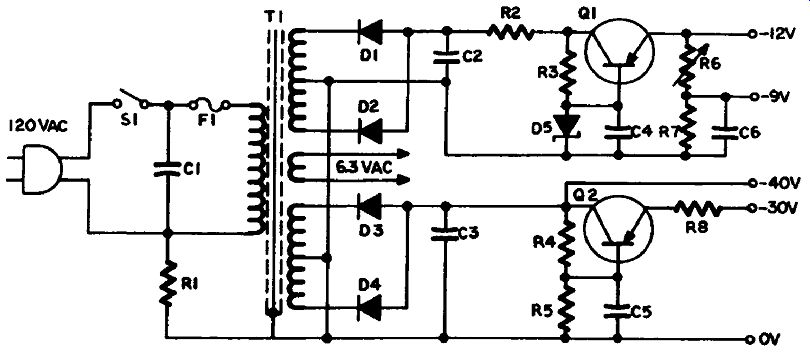 ave Power Supply
Figure 7.4
Uses
TV, radio and other electronic equipment with comparable requirements.
Detailed Analysis
Vacuum-Tube Full-Wave Power Supply: The input to this power supply is shown as a simple two-wire cord and plug. However, a third wire could be used, and would be connected to the junction between C1 and C2. These capacitors are usually of .01-microfarad capacitance and form, with R1 (100 kilohms), a filter for reduction of power-line interference (pops from operation of switches, interference from motors, and so on). A switch (mounted as part of the volume control), and sometimes a fuse, will also be part of the input circuit.
The principal secondary winding is the high-voltage winding,
of which the opposite ends are connected to the two plates of V1. The centertap is connected to the low side of the circuit via the fuse F1.
This centertap is the most negative point in the circuit.
The filament of V1 is heated by a special 5-volt AC winding. Electrons low from this filament alternately to each plate according to which end of the winding is positive. The resultant DC current is drawn through the filter and voltage divider from all the tubes in the set, which in turn draw electrons from their cathodes, which are sup plied from the low side of the supply.
The pi-filter (C3A, C3B, L1) operates in the same way as discussed under the AC-DC supply, and the voltage divider divides the +300V supply equally to give a +150V supply for the more sensitive tubes. C4 gives additional filtering to this supply.
Tube heaters get a 6.3 AC voltage from the other filament winding.
Some power transformers have more than one 6.3V winding, or a 12.6V winding with a centertap, or both. Color-coding for leads for power transformers is given in the Appendix.
SOLID-STATE FULL-WAVE POWER SUPPLY
Figure 7.4 really depicts two power supplies sharing one power transformer. The remarks made about the input to Figure 7.3 power supply also apply to this one, but the two main secondaries give rise to two sets of voltage outputs. The pair of semiconductor diodes in each case function in the same way as the 5UA4G tube of Figure 7.3, but require no heater current, so no filament winding is provided. The 6.3-volt winding shown is for dial lamps and such.
Transistors Q1 and Q2 are provided for voltage regulation, discussed later in this section.
Circuit Variations
The circuits of Figures 7.3 and 7.4 appear in many variations.
Sometimes there are two rectifier tubes instead of a dual tube, some times two dual tubes are connected in parallel.
As already mentioned, there can also be differences in the number and arrangement of windings on a power transformer.
Line filters can vary also from the examples shown, though the principles are the same.
The filter, voltage divider and regulation circuits can sometimes get quite complicated where many different supply voltages are required. However, they all work according to the principles explained in this section.
TRANSFORMERLESS VOLTAGE-DOUBLER POWER SUPPLY
Figure 7.5 illustrates a very popular type of power supply. It is similar to the AC-DC power supply of Figure 7.2, but capable of higher voltage and current output, which makes it suitable for economy TV use.
Distinguishing Features
1. Two diodes (rectifiers), usually solid-state.
2. Pi-filter with choke.
3. Series-sting of tube filaments.
4. No power transformer.
5. Connection to power line, on-off switch, fuse or fusible resistor.
Uses Radio, TV and the like.
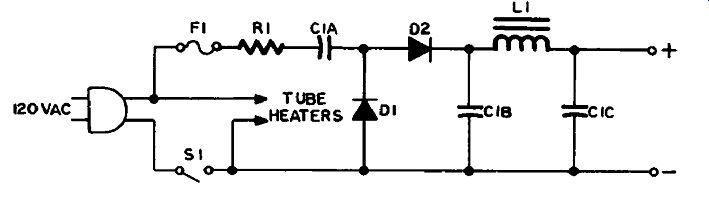
Figure 7.5 Transformerless Voltage-Doubler Power Supply
Detailed Analysis
With S1 closed the alternating power-line voltage is applied across C1A and D1. The lower side of D1 is alternately positive and negative. When positive, D1 conducts, allowing electrons to leave the right hand side of C1A. The other side of C1A is charged negatively. As D1 can only conduct in one direction the positive charge on C1A builds up to the peak value of the power-line voltage (120 X 1.4 = 168V). This positive voltage stored on C1A acts as a base, with the power-line AC superimposed on it, so that the voltage at the upper end of D1 is the algebraic sum of the DC and AC peak voltages. This voltage varies between +336 and 0 (+168 ±168) volts. The action of the rest of the circuit to the right of D1 is the same as that of Figure 7.2, except that the filtered DC voltage will be approximately 250 to 300 volts instead of 100 to 150 volts.
R1 is a surge resistor, a low- value resistor which controls the rush of current into C1A when SI is closed, which might otherwise destroy D1. It can be combined with the fuse F1 in a fusible resistor ("surgistor ).
This can withstand the heavy charging current which only lasts for a very short time, but melts if a short elsewhere in the set draws a sustained heavy current.
Circuit Variations
Although fundamental principles remain the same there are several different ways of arranging these circuits. Much of the variation is in voltage dividers and filters (discussed later).
A disadvantage of this type of circuit is that one side of the chassis (when using a metal chassis) is connected to the power line. To avoid this the low side may be connected to the chassis through a large capacitor located in series with C1B. This capacitor then replaces C1A, which is not required.
Considerable variation is also possible in the order in which the series-string of tube heaters is arranged. If there are very many it may be necessary to arrange them in two parallel strings (see Figure 7.8).
Occasionally a filament transformer is used instead, and the tubes are then connected in parallel. A filament transformer is a less expensive type of transformer which reduces the power-line voltage to 6.3 or 12.6 volts. (Such transformers are used for domestic purposes also, such as bells, thermostats, and so on.)
TRANSFORMERLESS VOLTAGE-TRIPLER POWER SUPPLY
The voltage-tripler circuit illustrated in Figure 7.6 works in exactly the same way as the voltage-doubler of Figure 7.5. Compare the two circuits. (Switch, fuse, heater connections and surge resistor have been omitted for convenience.) C1 and D1 store a positive charge in the same way as C1A and D1 ...
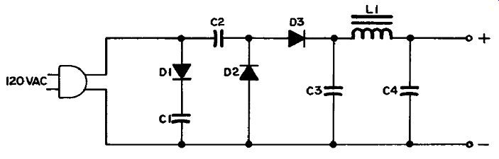
Figure 7.6 Transformerless Voltage-Tripler Power Supply
... in Figure 7.5. This additional voltage brings the output up to between 400 and 450 volts. Further capacitor diode pairs could be added to make voltage-quadruplers, -quintuplers, and so on, but capacitors that can stand higher voltages are expensive, so there is a practical limit to what can be done.
BRIDGE RECTIFIER POWER SUPPLY
Figure 7.7 illustrates a bridge rectifier circuit.
Distinguishing Features
Four diodes (not necessarily diagramed in a diamond pattern) connected across the secondary (or principle secondary) of a power trans former. This secondary does not have a centertap.
Uses TV, radio, and other electronic equipment with comparable requirements.
Detailed Analysis
When the lower end of the secondary winding is negative, electrons low via D2 to the load across the output terminals. From there the current returns through the filter L1-C2-C3 and D3 to the upper end of the transformer secondary. On the next half-cycle the polarities reverse, and the current lows from the upper end of the secondary winding through D1, and thence through the load and filter as before.
However, this time it returns through D4 to the lower end of the winding.
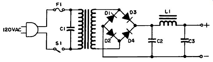
Figure 7.7 Bridge-Rectifier Power Supply
VOLTAGE DIVIDERS
Power supplies which have to provide for more than one B voltage may do so by means of voltage dividers. A voltage divider consists of several resistors connected in series between the high and low sides of the output of a power supply. The current lowing through these resistors does the following:
(1) It stabilizes the power supply voltage.
(2) It discharges the capacitors when the equipment is turned off.
(3) It gives a voltage drop across each resistor which is proportionate to the resistance value.
In Figure 7.8 A, three resistors with values as shown are connected across a 240-volt supply. The total resistance is 40 kilohms, so the voltage divides proportionately as follows:
Resistor Voltage Drop
10K 60V 15K 90 V 15K 90V 40K 240V
In B a similar arrangement is shown connected across a 650-volt supply. However, the low side of the main circuit is not connected to the bottom of R5, but between R4 and R5, making this the zero reference. As a result the voltage at the bottom of R5 is negative (below zero) with respect to the zero point. This has the advantage that by pass and decoupling capacitors with lower working voltages can be used, which makes for greater reliability and less cost.
However, in transformerless power supplies there is a limitation on how much current can be supplied. If the voltage divider consumes too much it takes it away from the tubes for which it is supplied. In the examples shown, A draws 6 milliamperes, and B 10 milliamperes.
In a TV set this may be more than can be tolerated. Consequently an arrangement similar to that shown at C may be used instead. This uses the voltage drop across a tube which draws considerable current (such as an audio-output tube) to provide two levels of voltage.
The current passing through V4 is equal to the combined currents of V5, V6 and V7.
Two 100-volt tubes may be connected across a 200-volt supply in ...
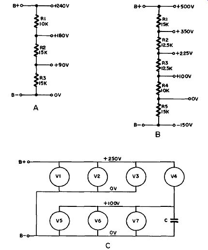
Figure 7.8 Voltage Dividers
... series, provided they draw the same current. An example of this economical trick is shown in Figure 2.25.
VOLTAGE REGULATION
The voltage output of any of the power supplies discussed so far will vary according to the load and line voltage. In many cases this does not matter, but where a constant output is essential a voltage regulator circuit must be provided.
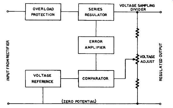
Figure 7.9 Voltage Regulation
A voltage regulator consists of the elements illustrated in block form in Figure 7.9. It is connected to the output of a power supply (such as a bridge rectifier, Figure 1.1).
If the output voltage changes, the voltage at the movable arm of the "voltage adjust" resistor changes, and this change is sensed by the comparator, which monitors it constantly against the reference. The comparator passes on this information to the error amplifier, which in turn controls the series regulator.
In Figure 7.10 is shown a voltage regulator which also contains an overload protection circuit (R1, Q1). If a short circuit occurs some where so that a very heavy current is drawn through R1, the base emitter junction is forward-biased so that current can low through Q1 and R4. The voltage drop across R4 is such that the base-emitter junction of Q4 (the error amplifier) is reverse-biased, so Q4 is cut of.
As no current can now low through R6, the forward bias on the base emitter junction of Q5 disappears, and it also ceases to conduct.
When the overload is removed, so that normal current lows through R1, Q1 returns to its usual non-conducting condition, and Q4 and Q5 become conductive again. R1 has a resistance value of .5 ohm or less, so normal current does not produce enough voltage drop to bias Q1 into conduction. C3, a large-value capacitor, absorbs noise and spikes so that operation is not interrupted by transients.
D1 is a zener diode connected in series with a limiting resistor R2, ...
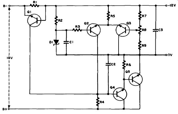
Figure 7.10 Voltage Regulator
... and it gives a reference voltage of 9 volts at their junction. It also clamps the voltage on the base of Q2 at a value close to this. The base of Q3 is connected to the movable arm of R8. If the voltage at this point changes, due to a change in the output voltage of the power supply, the bias on Q3 changes. This changes the resistance of Q3, so that the current lowing through it changes.
Q2 and Q3 form a comparator circuit, and share R5. When the current through R5 changes (which it does when the current through Q3 changes) the voltage drop across R5 also changes. This changes the bias on Q2, so that its resistance changes in accordance with the increase or decrease of oulput voltage across R7, R8 and R9.
The change in voltage on the base of Q4 due to the change in voltage drop across R4 is amplified and applied to the base of Q5, causing this transistor to decrease or increase resistance to correct the rise or fall in the output voltage. Since the output of the power supply is de pendent on the voltage at the movable arm of R8 the value of the output voltage can be adjusted by moving this control.
This is a very sensitive circuit, and is used extensively in well regulated power supplies. The identical circuit will also be met where Q2 and Q3 are a dual-triode tube, Q4 is a pentode, Q5 a triode (or two or more triodes in parallel) and D1 is a gas glow-tube.
Circuit Variations
A circuit which is also often used is shown in Figure 7.11. This combines the comparator and error amplifier in one tube, V3. Changes in voltage at R9 change the voltage on V3's grid, thereby changing its resistance, and consequently the current through V3 and R5. The resultant change of plate voltage appears on V2's grid, so that when the output voltage rises V2's resistance increases to correct it. The neon glow-tube V1 clamps the cathode of V2 at approximately half the output voltage.
Very much simpler and more economical circuits were illustrated in Figure 7.4, where Q1 and Q2 are also voltage regulators. Here only one transistor in each supply is doing the work of all four in Figure 7.10. Of course, the regulation is nowhere near as good, but it is much more economical, and adequate for hi-fi and the like.
In the case of Q1, D5 is also a zener diode, which clamps the base of Q1 to approximately 12 volts. Any variation in output voltage is felt by the emitter, changing the emitter-base bias, and controlling the conductivity of Q1. R6 is a variable resistor. By adjusting R6 the 9 volt output can be set to the exact value.
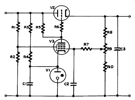
Figure 7.11 Voltage Regulator
In the case of Q2 no zener-diode; reference is provided, and consequently regulation is less efficient. Line-voltage variations are not compensated for, only load variations. The 40-volt supply is not regulated at all.
HIGH-VOLTAGE POWER SUPPLIES
Low-voltage power supplies, such as those we have been discussing, provide voltages up to around 500 volts. Applications needing higher voltage are served by high-voltage power supplies.
High-voltage power supplies fall into two classes: those where power is required, and those where voltage is the main consideration.
HIGH-VOLTAGE POWER SUPPLY FOR TRANSMITTER
Figure 7.12 illustrates one of the first type, to provide power for a transmitter. It is a full-wave power supply which differs only from a low-voltage supply in tube and transformer sizes. Its distinguishing features and mode of operation are the same as those for Figure 7.3, except for two additional features.
L1 is a swinging choke. This is a choke operated with the core close to saturation, so that the inductance varies with the current (see discussion of Magnetic Amplifiers in section 3). It has a smoothing effect on the DC pulses coming from the rectifier tubes.
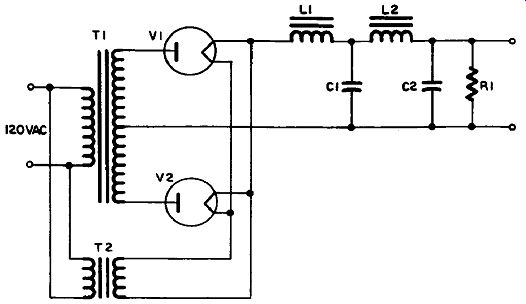
Figure 7.12 High-Voltage Power Supply for Transmitter
R1 is a bleeder resistor. By providing a constant current drain it stabilizes the output voltage, and also discharges the filter capacitors when the power is switched of.
Note that there are two transformers. T1 is called the plate trans former. It is not uncommon for the AC potential across its secondary to be 2000 volts, or 1000 volts across each half.
T2 is the filament transformer. It provides the current to heat the filaments of V1 and V2. Since the DC potential on these filaments may be 1000 volts or more this transformer has to be well insulated. The tungsten filaments of these tubes will usually draw a heavier current than those used in smaller power supplies.
The tubes themselves are often heavy-duty mercury-vapor rectifiers, such as 816s.
Capacitors C1 and C2 are generally of much smaller capacitance than those used in low-voltage power supplies. Electrolytics are not able to withstand the higher voltage, so these will probably be oil-bath types. Because they can only be around 5 or 10 microfarads at most, chokes with considerably higher inductance values have to be used.
HIGH-VOLTAGE POWER SUPPLY FOR CATHODE-RAY TUBE
Cathode-ray tubes (CRTs) are mostly used in oscilloscopes, although a TV picture tube is really a CRT also. However, picture tubes are classed by themselves in this section. CRTs require a high anode to-cathode voltage. In many cases this may be as much as 12 kilovolts, but the current drawn is very small. Consequently the type of power supply shown in Figure 7.13 is used. TV HV supplies are similar, but are discussed in the next section.
Distinguishing Features
The output of an oscillator V1 is stepped up by a high-voltage trans former T1. The secondary voltage is rectified by diodes and filtered by resistors and capacitors, and the DC output is applied to the CRT, positive going to the anode, negative to the cathode and grid. A sample is often fed back to a comparator which controls the oscillator.
Uses
Mainly in high performance oscilloscopes or similar equipment.
Detailed Analysis
In Figure 7.13 V1 and the primary of T1 form a Hartley oscillator, in which the inductor resonates with the distributed capacitance of the circuit (see section 4). The supply voltage for this oscillator comes from the low-voltage supply of the oscilloscope. The frequency of oscillation will be in the order of 50 to 100 kilohertz. Filtering such a frequency is easier, and requires much smaller capacitors, which is an important consideration at high voltages.
Two voltages are supplied by this circuit. A positive voltage of 10 kilovolts is required for the CRT anode, and a negative voltage of 2 kilovolts for the cathode and grid.
The anode voltage is obtained by using a voltage tripler (see Figure 7.6). However, the higher frequency makes filtering easier, so smaller values are required for C5, C6, C7 and C9, and the choke is replaced by R10 and R11.
The cathode voltage, being much lower, is provided by the half wave rectifier circuit consisting of D1, C4 and C8. Because of the higher frequency and the very small load involved this simple filtering is sufficient.
R7, R8 and R9 form a voltage divider in which R9 is very much larger than the other resistors. The voltage sensed at the movable con tact of R8 is only a small percentage of the total. This voltage is fed to the right-hand grid of the dual-triode V2.
The right-hand cathode of V2 is connected to the negative B supply (usually -150 volts). This supply is well regulated, so the cathode voltage is constant. Consequently any change in the grid voltage is followed by a change in the plate voltage. This error voltage is coupled directly to the left-hand grid, and the resultant amplified change of plate voltage appears on the screen grid of V1.
This in turn changes the amplitude of the Hartley-circuit oscillations. If the negative voltage on R8 decreases, the right-hand plate voltage decreases, the left-hand grid voltage decreases, the left-hand plate voltage increases and the screen-grid voltage of V1 increases.
This causes the oscillations to increase in amplitude, so that the high voltage rises.
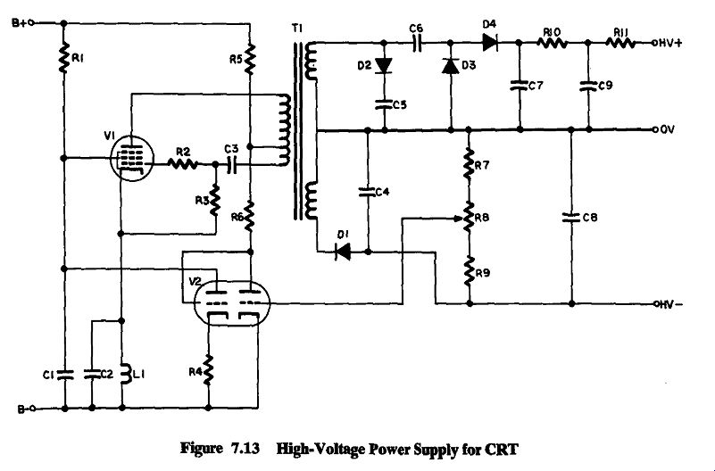
Figure 7.13
The high voltage is set to the exact potential required by adjusting R8. L1 is a choke to keep the oscillator signal from coupling into the power supply (whence it would be distributed all over the set). R1, R5 and R6 are voltage-dropping resistors. R4 is the bias resistor for the left-hand half of V2; C1 and C2 are bypass capacitors.
Circuit Variations
In some models solid-state diodes may be replaced by high-voltage vacuum-tube rectifiers. V1 and V2 also may be transistors. The oscillatory circuit may be any suitable type instead of a Hartley. Part of the high voltage may go to the CRT intensity control. The anode or cathode may have independent supplies.
Finally, smaller or more economical equipment may obtain a sufficiently high voltage from a secondary on the low-voltage power supply transformer.
TV HIGH-VOLTAGE SUPPLY
Figure 7.14 shows a typical high-voltage supply for the picture tube of a TV set.
Distinguishing Features
a. One or more pentode or beam-power tubes, often with the plate connection to a cap on top of the tube, as symbolized in V1.
b. A diode with indirectly heated cathode (V2), frequently having an adjustable inductor in its plate circuit.
c. A transformer, usually an autotransformer as shown, with connections to V1, V2, the picture-tube horizontal yoke coils, a high-voltage rectifier (V3), and the picture tube itself (V4).
d. In color TV sets an additional tube, usually a triode (V5), is added for regulation.
e. Any of these tubes may be replaced by an equivalent semiconductor.
Uses
TV high-voltage section.
Detailed Analysis
Figure 7.14(A) illustrates a circuit which has become pretty well standardized for black-and-white sets. It has some similarities to the circuit in Figure 7.13. For example, the drive is from an oscillator ...
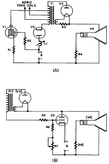
Figure 7.14 TV High-Voltage Supply
... and, because of the higher frequency, filtering is much simpler.
DC Subcircuit: Electron low is from B- via R1 and V1 to T1 , through T1 to V2, and via V2 and L1 to B+; also, from B- via R4 to V4, and via V4 and V3 to T1, and thence via V2 and L1 to B+.
AC Input Subcircuit: The horizontal oscillator (not shown) drives V1, which is a power amplifier, often called the horizontal-output tube, and similar to an audio-output stage. However, the oscillator frequency is 15.75 kilohertz, so it is a little too high for most people’s hearing.
The oscillator signal is a modified sawtooth. V1 is biased so that current does not begin to low until the sawtooth is halfway up its rise.
At this point the electron beam in the picture tube is halfway along one of the horizontal lines. In other words, no current is lowing in the horizontal yoke coils to move it one way or the other. But when V1 starts conducting, an increasing current in the yoke coils causes a magnetic field to build up which drives the electron beam at a steady rate to the right-hand edge of the picture-tube screen.
At this point the peak of the sawtooth arrives, and the grid voltage on V1 dives down to its starting value. V1 cuts of abruptly, and the energy stored in the magnetic field of the yoke coils is suddenly re leased in a tremendous surge of current in the opposite direction.
The reverse current whips the beam back to the left-hand side of the screen (during the brief period when it is blanked out), and also cuts of V2 (the damper tube) by making its cathode more positive than its plate.
However, the positive surge now reverses in a negative direction, which starts the damper tube conducting again. This puts a heavy load on the resonant circuits, damping out the high-amplitude oscillations so that the energy is now released through the yoke coils in such a way as to allow the beam to return to the center of the screen. The circuit is designed so that the beam moves at a steady rate across the screen, with a smooth transition at the midpoint.
The high voltage is generated by the first surge of current, when V1 cuts of. Since V2 is also cut of, loading on T1 for the moment is minimal. The pulse amplitude can be as much as 2 or 3 kilovolts.
T1 steps this up to 12 or 15 kilovolts for black-and-white sets, 25 kilovolts approximately for color.
These positive pulses are rectified by V3, and fed to the anode of V4. The inner and outer conductive coatings on the envelope of the picture tube are connected as shown, and form a capacitor (with the glass as dielectric) that, with the internal resistance of V4 in series with R4, is sufficient to smooth the positive pulses into DC.
Filament voltage for V3 is obtained from an additional winding (usually only a turn or two) on T1. R3 is a low-value resistor to protect the filament, and is often omitted.
L1 is the linearity control. Adjusting it modifies the waveform of VTs plate current and also V2's discharge waveform. Another vari able inductor (not shown) is usually connected in parallel with part of T1. This is the width control. It has the effect of varying the turns ratio of T1, and hence the step-up ratio.
In Figure 7.14(B) is shown an additional circuit used in color TV sets. V5 is a voltage regulator. Its grid voltage is set by adjusting R7.
This varies the conductivity of V5, and so changes its loading effect on the high-voltage power supply.
The picture-tube load on the high-voltage power supply is varying all the time with changes in picture brightness. A bright scene increases the load on the high voltage supply. This is reflected in a fall in the voltage across the voltage divider R5, R6 and R7. As a result V5' s grid voltage drops and the tube's internal resistance rises, so that it loads the high voltage less. When the scene is dark the opposite hap pens. In this way V5 compensates for changes in the loading effect of V4, so as to maintain a constant voltage on its anode. This is important for good color.
Circuit Variations
All the tubes except the picture tube may be replaced by equivalent semiconductors. However, the single high-voltage rectifier tube is usually replaced by a solid-state voltage doubler, tripler or even quadrupler. (A quadrupler is a tripler with an additional diode-capacitor pair, as mentioned in the discussion of Figure 7.6.) This gets the necessary high voltage from the flyback transformer, even though the input voltage to it-from a transistor-is much lower than would have been the case with a tube.
Regulation may also be performed on the primary side of T1. In a circuit somewhat similar to Figure 7.13, V1 is controlled to maintain a constant voltage output.
DC INVERTERS
So far we have been mostly concerned with converting AC power to DC power. Circuits for converting DC to AC are also required.
Since transformers will not operate on DC it is necessary to convert DC to AC before it can be applied to the primary of a transformer to obtain a voltage step-up.
Oscillators convert DC to AC, of course, but are not generally suit able for power supplies unless the power requirements are small, as in high-voltage power supplies (Figure 7.13). Where the load is heavier some device must be used that " chops " a considerable DC current into pulses.
Such devices are electronic or mechanical, and are used in circuits called DC inverters. Electronic devices include thyratrons, ignitrons and silicon-controlled rectifiers (SCRs). Mechanical devices consist of choppers, vibrators or dynamotors.
In Figure 7.15(A) is shown a DC inverter circuit with a thyratron.
The same circuit could also use an ignitron (C) or an SCR (D).
Distinguishing Features
A gas-filled triode (note black dot, which indicates gas content instead of vacuum) is connected in a circuit with a DC input, and an AC output.
No DC operating voltages are provided from a power supply, as this is the power supply.
An ignitron is even more recognizable, and so is an SCR, because of their distinctive symbols.
Uses
Heavy-duty power supplies converting DC to AC.
Detailed Analysis
A thyratron is a hot-cathode gas tube in which the control grid acts as a switch to turn it on. As long as the grid remains negative the tube cannot conduct, although the anode is positive, but a positive voltage on the grid initiates electron low. Once this has started it cannot be stopped by making the grid negative; the anode must also be made negative.
An ignitron is a cold-cathode gas tube. The control element is the ignitor, which is a carbide-tipped rod dipping slightly into the surface of a pool of mercury. The mercury is the cathode. In other respects the ignitron is the same as the thyratron, except it can handle heavier currents and does not require any heater current for the cathode.
A silicon-controlled rectifier is the semiconductor equivalent of a thyratron or an ignitor. It is a diode with a third lead to a gate. With the proper bias applied to the gate it switches to a conducting state, when it can pass a heavy current.
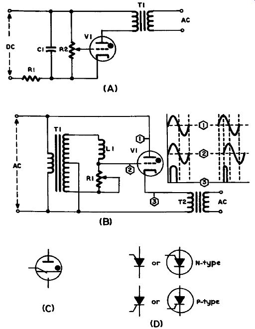
Figure 7.15 Controlled Rectifier Circuits
In Figure 7.15(A), before any voltage is applied to the input C1 is not charged. When power is turned on all the current lows into C1 at first, so no voltage appears across V1 and the primary of T1. Consequently V1 does not conduct. The voltage builds up across C1 at a rate determined by the R1-C1 time-constant. When it reaches the value that makes V1 ire, the gas in the thyratron ionizes, and V1 goes from being a very high resistance to a very low one. This enables C1 to discharge practicall1 tries to maintain current low even after C1 is totally discharged, there is momentary overshoot which serves to reverse the voltage across V1, so that it switches back to a non-conducting state. The cycle is now repeated as the input voltage again begins to recharge C1 through R1.
R2 is used to adjust the voltage on the grid of V1 for best performance. The chopped DC current passing through the primary of T1 induces an AC output in the secondary. The output voltage depends on the turns ratio of T1.
Dynamotors are used to convert DC to AC or to DC of a higher voltage. They are essentially DC motors with a secondary winding on the armature from which the output is obtained, and so are really rotating transformers.
Choppers and Vibrators are electromechanical devices for interrupting the low of current, operating in the same way as a buzzer or telephone bell. At one time all automobile radios obtained their power from the car's battery by using a vibrator in a circuit similar to Figure 7.16. Although modern car radios are solid-state it’s worth noting this power supply because the principle of chopping DC and converting it to AC is well illustrated by it.
It is readily identified by the vibrator, which consists of an electro magnet, symbolized by the rectangle, and a reed. The reed rests against the two lower contacts (arrows). When SI is closed current flows from the negative side of the 12V supply to the reed. Some of the current then lows through the lower half of the primary of T1 (via the right hand contact) and back to the positive side of the supply from the centertap. The rest lows via the left-hand contact, through the electro magnet, and back to the positive side of the supply.
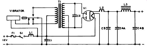
Figure 7.16 Vibrator Power Supply
The electromagnet, being magnetized by the current, attracts the armature on the reed. This swings the reed over to the upper contact, breaking the connection with the two lower contacts. Current now lows in the upper half of T1’s primary and back via the centertap, but in the opposite direction to that which lowed in the lower half. However, the current lowing in the electromagnet is now cut of, its magnetic field collapses, and the reed returns to its initial position, where the cycle starts again.
You can see that the alternate surges of current in opposite directions in T1’s primary are an AC current, which is stepped up by the secondary, after which it is rectified and filtered by a full-wave power supply similar to that in Figure 7.3.
The cathode of V1 is indirectly heated by the 12-volt battery supply, as are all the other tube cathodes.
C2 is a buffer capacitor. It is used to reduce voltages surges ("spikes") that might damage the following parts. L2 and C3 together form a hash suppressor that filters out RF noise from the vibrator. L1 and C1 do the same for RF noise picked up by the car’s wiring (such as spark plug noise).
Thyratrons as Industrial Power Controls
Thyratrons are also used to control AC power for machinery by means of a phase-shifting circuit such as that in Figure 7.15 (B).
The AC power source is connected to the anode and cathode of V1 as shown. The transformer T1 is also connected to the power source.
Because of the centertap the polarity of the signal at the upper end of the secondary winding is opposite to that at the lower end.
The phase of the signal applied to V1’s grid, relative to that of the signal on the anode, depends on the setting of R1, which forms a phase-shifting network with L1. If both signals are of the same phase, positive excursions will be applied simultaneously to anode and grid, and the thyratron will conduct for the maximum length of time until both signals swing negative, as illustrated in the left-hand set of wave forms.
However, if the phase of the grid signal is shifted, as shown in the right-hand set of waveforms, the period of conduction is shortened to the length of time during which the positive excursions overlap, so that the output power is reduced accordingly. R1 shifts the phase up to 90 degrees, with a corresponding variation in output from full power to zero.
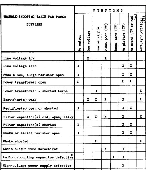
---------- SUPPLIES
-------------------