DEMODULATORS ARE the opposite of modulators. They recover the information from the modulated radio-frequency signal. For this reason they are also called detectors. Many de modulator circuits are built around one or more diodes, though triodes and specially designed tubes are used also.
In the process of modulation an RF and an audio or video signal were mixed together to produce a carrier with sidebands containing the audio or video information, which could then be radiated through space. At the receiver another signal was mixed with the RF signal and its sidebands to convert them to the IF frequency. Now, after amplification and removal of all undesired elements in the IF section, we have to get rid of the IF carrier in such a way that we are left with the audio or video information alone.
Detector circuits are also a source of feedback voltage to provide for automatic gain or volume control.
DIODE DEMODULATOR-CRYSTAL DETECTOR
Figure 6.1 shows a semiconductor diode used to demodulate an AM radio signal. Such a circuit may be called a diode demodulator or crystal detector circuit.
Distinguishing Features
This circuit contains a semiconductor diode, and is located between the last IF stage and the first AF stage of a superheterodyne AM receiver (radio or television).
The input is via the last IF transformer, and the output, in a radio receiver, usually is taken from the moving arm of a potentiometer ( volume control).
In many cases a DC voltage for automatic volume (gain) control is extracted from the stage by means of a filter (R1, C2, R2, C3, in Figure 6.1).
No external DC is supplied to the circuit, for the diode is really a resistor which has much more resistance to current lowing in the direction of the arrow than against it.
Uses
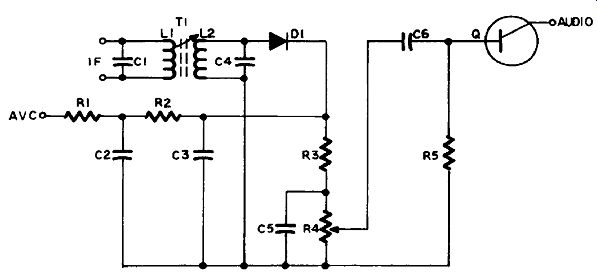
Figure 6.1 Crystal Diode Detector and AVC
AM radio and television receivers.
Detailed Analysis
In Figure 6.1 the output from the IF amplifier (see section 2) is coupled into L2, the secondary of T1, which with C4 is resonant at the IF frequency.
As this is an AC signal the upper and lower ends of L2 are alternately positive and negative. If there were no D1 an alternating current would low in the circuit connecting L2, R3 and R4, but as the diode only allows current to low in the direction opposite to the arrow, it can only do so when the upper end of L2 is positive.
This results in a succession of pulses of direct current through R4 and R3 at the IF frequency, each one producing a voltage drop across R4 so that its upper end is positive with respect to its lower end. As a result C5 becomes charged so that its upper end is positive also.
During the interval between each pulse C5 starts to discharge by sending a current through R4 in the opposite direction, but before it can lose much the next positive pulse recharges it. As a result its charge stays very close to the amplitude of the positive voltage pulse developed across R4.
In the absence of modulation the IF carrier would be of constant amplitude, which would produce a constant voltage on C5. However, as you know, in amplitude modulation the amplitude of the signal is varying all the time in accordance with the audio information impressed on it, and so the voltage dropped across R4 varies, and the voltage on C5 rises and falls with it. The values of R4 and C5 are such that although C5 cannot discharge fast enough through R4 to follow the IF fluctuations it can follow the audio-frequency ones. The voltage across C5 and R4 therefore reflects the audio information originally impressed on the RF carrier. The movable arm of the potentiometer picks of as much of this AF voltage as will give the output desired, and couples it via C6 to the base of the audio amplifier transistor in the next stage.
Automatic Volume Control
The diode D1 is connected so that current pulses lowing through R4 and R3 give a positive voltage at the upper end of R3 with respect to the low side of the circuit. The filter R1, R2, C2, C3 smoothes out these pulses so that pure DC is provided for application to an earlier stage or stages of the circuit. This voltage varies only with the average amplitude, or strength, of the carrier, not with the audio fluctuations.
For strong signals it will be higher, for weak it will be lower. When applied to previous stages it reduces the gain proportionately to over come variations in the strength of the radio signal as received.
The polarity required for AVC voltage depends upon the application. For PNP transistors it will be positive, as shown, but for NPN transistors and vacuum tubes a negative voltage is necessary. In this circuit reversing the polarity of the diode would reverse the polarity of the AVC voltage, if a negative voltage was required.
Circuit Variations
As explained above, the polarity of the diode may be reversed, or a different take-of point may be used to provide the AVC voltage of the proper polarity and amplitude.
When used in a TV receiver the diode detector circuit (Figure 6.2) has to handle the much greater bandwidth of the video signal (4.5 megahertz), while at the same time eliminating everything above that frequency. The values of C1, L3, C3 and L4 are chosen so that frequencies above the video frequency are so attenuated that they cannot get through the video amplifier to appear as interference on the TV screen. If a variable resistor like R4 (Figure 6.1) was provided in Figure 6.2 it would be a contrast control. However, this will more often be found in the next stage, the video amplifier discussed in section 2.
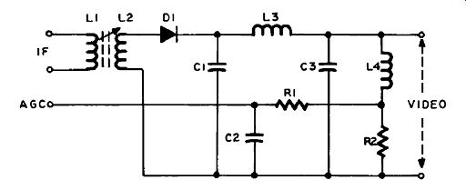
Figure 6.2 Video Detector Automatic Gain Control
AGC considerations in the video detector are similar to those for AVC in a radio. They are different names for the same thing.
However, the type of AGC shown in Figure 6.2 is not always adequate for TV, and many receivers obtain it from a different circuit (Figure 6.4). Also, it is quite a common practice, if AGC is taken from the video detector, to make R2 a variable resistor, with R1 connected to the moving arm, so that the AGC voltage may be adjusted to suit local conditions.
Another circuit variation is the addition of a second diode as AGC rectifier, parallel with L4 and connected to conduct on negative alter nations of the IF signal if negative AGC voltage is required (in which case D1 would face the other way also). In a vacuum-tube receiver a dual-diode tube may be used, or a triode connected so that the grid acts as the anode for one diode and the plate as the anode for the other, the cathode being common to both. Of course, the two diodes may also be semiconductors.
Peak Detector
As you have just seen, diode demodulators operate by averaging the amplitude of the rectified IF signal. However, if a single pulse at the IF frequency came along with a much greater amplitude it would pass unnoticed.
But if the circuit in Figure 6.2, for example, consisted only of the IF transformer, D1 and C1, then C1 would charge up to the maximum voltage of the pulse, and remain there because there would be no resistor through which it could discharge.
This is the principle of the peak detector, which is used for detecting transients (momentary voltage surges) that otherwise would not be observed. After each measurement of the voltage, the capacitor is discharged by a gate (see section 9), so as to reset it for further measurements.
The peak detector is not a demodulator, but is included here because it is a form of diode detector which you may run across, and therefore should know about.
VACUUM-TUBE DIODE DETECTOR
Vacuum-tube diodes perform in the same way as semiconductors, allowing current to low through them in one direction only. They have the disadvantages of being larger and requiring a heater current to heat the cathode. However, the invention of the dual-diode-triode tube shown in Figure 6.3 enabled manufacturers to combine the diode detector function with the first audio amplifier stage in one tube, which was an important saving of cost in the heyday of vacuum-tube radios, and as these sets are still being produced the circuit is by no means superseded by the semiconductor type.
Distinguishing Features
The circuit contains a dual-diode-triode tube, and is located between the last IF stage and the audio output stage of a superheterodyne AM receiver.
The input is via the last IF transformer, and the output to the triode section of the tube is taken from the moving arm of a potentiometer (volume control).
An external DC supply is required for the operation of the triode section of the tube, but not for the diode. DC voltage for AVC is extracted from the diode stage by means of a filter (R1, C2, R2, C3).
Uses
AM tube radios.
Detailed Analysis
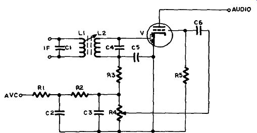
Figure 6.3 Vacuum-Tube Diode Detector and AVC
The input signal is coupled from the previous IF stage (see section 2) by the IF transformer L1-L2, which is tuned to resonance at the IF by C1 and C4. The triode section of V is used for audio voltage amplification, and as this circuit is explained in section 2 it will not be explained here. C6 and R5 in Figure 6.3 correspond to C1 and R1 in Figure 2.1.
The diode section of V consists of the cathode and two anodes beside it. When electrons are emitted from the cathode they will be attracted by a positive anode voltage, and current will low. When the anode voltage is negative they will be repelled, and no current will low. When the upper end of L2 is positive, current will low in the circuit from the lower end of L2, via R3 and R4 to the cathode of V, and from the diode anodes back to the upper end of L2. When the upper end of L2 swings negative the diode blocks current low in this circuit.
When the diode conducts, electrons low from V down through L2 to charge C5 with a voltage equal to the amplitude of the IF signal.
When the diode does not conduct, the charge on C5 begins to leak away through R3 and R4 (with which it is in parallel). However, if the values of C5 and R3 and R4 are chosen correctly C5 will not discharge very much before the next pulse recharges it, because it has to discharge through the high resistances of R3 and R4, whereas it charges through V, which has a very low resistance when conducting.
This means that C5 cannot follow the individual IF cycles, and re mains virtually at the IF amplitude all the time. But this amplitude is fluctuating at the audio rate because of the audio signal with which it was modulated. The values of C5 and R3-R4 are such that the voltage on C5 can follow the audio fluctuations. Consequently the voltages across R3 and R4 vary with the audio modulation of the carrier.
The movable arm of the variable resistor R4 picks of as much of the voltage dropped across R4 as the user desires, and couples it through C6 to the next stage. C6 blocks the DC part of the signal, so that only AC appears at the grid of V.
The DC component for AVC is derived from the average or un modulated amplitude of the IF carrier, and is extracted by the filter circuit R1, C2, R2, C3, as in the crystal diode circuit of Figure 6.1.
KEYED AGC
Simple AGC from the diode detector circuit, as shown in Figure 6.2, is not as efficient for TV as the circuit shown in Figure 6.4, be cause it cannot follow rapid fluctuations of the carrier strength, such as occur when an airplane lies over, when the picture would flutter severely. A keyed AGC circuit is designed to overcome this, and to reduce noise interference also.
Distinguishing Features
Although the circuit in Figure 6.4 looks like an amplifier you’ll notice one startling difference right away. The B + voltage is connected to the cathode of the tube! It is also connected to the screen grid, but not to the plate as in all regular amplifiers.
Instead, the plate is connected to the output of the horizontal deflection section, so as to apply powerful flyback pulses to it.
Uses To provide AGC voltage in TV sets.
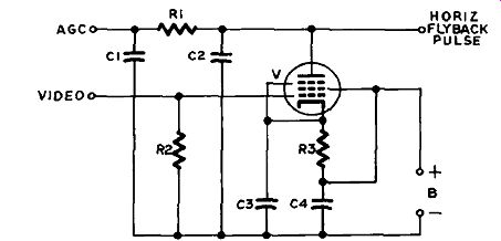
Figure 6.4 Keyed AGC
Detailed Analysis
DC Subcircuit: In Figure 6.4 B+ voltage is applied to the screen grid of V, and to the cathode via R3, but electron low can only take place when a high-voltage pulse is present on the plate to make it positive with respect to the cathode. These pulses are frequently coupled to the plate through a capacitor to block DC voltages, and have a repetition rate of 15.75 kilohertz.
AC Input Subcircuit: A portion of the output of the video amplifier is applied to the control grid of V. The relationship between the cathode voltage, the control-grid voltage and the plate voltage (when a positive pulse is on it) is such that the grid voltage would prevent conduction at any time except when a horizontal sync pulse is received.
In other words, the tube can only conduct when both a flyback pulse is present on the plate and a horizontal sync pulse is present on the control grid. Furthermore the amount of current it can pass depends upon the strength of the sync pulse on the control grid.
AC Output Circuit: The bursts of electrons lowing away from the plate charge C2 negatively. This capacitor acts like a storage battery, current Rowing out of it between charging pulses through the filter network R1-C1.
The voltage on C2 varies with the amount of current passed by V, which in turn depends on the strength of the positive-going pulses applied to the control grid.
Circuit Variations
In the circuit in Figure 6.4 the plate of V would be connected directly to a separate insulated winding on the horizontal output trans former. In other cases the source of flyback pulses may be a tap on the main winding, the width control inductor, or damper circuit. As mentioned before, they are frequently coupled through a capacitor, and sometimes through a dropping resistor.
When flyback pulses are coupled through a capacitor, C2 may be replaced by a resistor. The coupling capacitor then acts as storage for the output current pulses from the tube.
The control-grid signal may be obtained from the sync amplifier instead of from the video amplifier.
A variable resistor is often placed in series with R3 and the B+ voltage in order to adjust the bias on the tube to compensate for the average strength of signals in the area where the set is operated. This is usually called the AQC control.
GRID-LEAK DETECTOR
Figure 6.5 illustrates a grid-leak detector. Though it is not often encountered anymore, it is particularly good on weak signals, so is sometimes used experimentally. However, some TV sets use it, as mentioned previously under automatic gain control.
Distinguishing Features
A triode with a tuned resonant circuit for RF or IF in its input, with an audio or video output.
The grid-leak resistor R1 may be shown paralleling C2, as in Figure 6. 5, or connected directly to the low side of the circuit, as R1 in Figure 2.1. Effectively, the connections are the same, since the first really connects to the low side of the circuit through the coil.
Uses
Radio receivers (not superheterodyne), and some TV detector and AGC circuits.
Detailed Analysis
DC Subcircuit: In Figure 6.5 electron low is from B- via V and R2 to B-K Electrons collecting on the grid of V return to the cathode via R1 and L2 (or R1 alone if connected direct to the low side of the circuit).
AC Input Subcircuit: RF or IF signals inductively coupled from L1 to L2 (which is tuned by C1 to be resonant at the desired frequency) are coupled by C2 to the grid of V. When the signal cycle is such that the upper end of L2 is positive, the lower end is negative. The grid and cathode of V act as a diode, and because the positive voltage of L2 is connected through C2 to the grid the " diode" conducts. When the signal polarity reverses so that the grid is driven negative, the " diode" does not conduct. This action is similar to the diode detectors discussed earlier in this section.
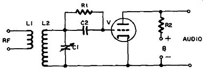
Figure 6.5 grid Leak Detector
When the "diode" conducts, electrons low from the cathode to the grid, and charge C2 so that the side connected to the grid is negative and the other side is positive. A voltage is developed across C2 which varies in amplitude with the modulation on the RF signal. Again, this action is the same as you saw in Figure 6.1, where an audio voltage was developed across C5.
As far as this audio voltage is concerned L2 is a straight piece of wire, so you have in effect only C2 and R1 connected between grid and cathode. V amplifies this audio voltage in the same way as any other audio voltage amplifier (see section 2).
AC Output Subcircuit: The output audio signal voltage appears across R2, and in a radio is coupled into the next stage, or to headphones. The use of this circuit in a TV set was covered under video detectors and AGC, and also as follows under circuit variations.
Circuit Variations
When this circuit is used in a TV video detector stage the cathode grid diode replaces D1 in Figure 6.2. The triode amplifier output is then filtered and becomes an AGC voltage as in the AVC and AGC voltage circuits shown in Figures 6.1 through 6.4.
REGENERATIVE DETECTOR
The regenerative detector uses positive feedback to return a portion of the signal in the output to the input circuit as shown in Figure 6.6.
Distinguishing Features
The feedback coil L2, the RF input, the audio output and the variable resistor R1 in the grid circuit of V, taken together, enable you to tell this circuit from an RF amplifier or an oscillator.
Uses
Sometimes used in experimental receivers because it is very sensitive, and can be used to receive both modulated and CW signals.
Detailed Analysis
DC Subcircuit: In Figure 6.6 electron flow is from B- via V, L2 and the primary of T1 to B+.
AC Input Subcircuit: The RF signal picked up by the antenna is coupled from L1 to L3, which is tuned to resonance by C1, and then applied via C2 to the diode consisting of the grid and cathode of V.
Demodulation takes place in the same way as in the grid-leak detector of Figure 6.5.
AC Output Subcircuit: The audio and RF signals present on the grid appear in the output after amplification by the triode V. The audio is coupled to headphones or to another stage. The RF signal is coupled by L2 back into the input, where it reinforces the signal applied to the grid. The degree of coupling sometimes can be adjusted by moving L2 closer to or further from L3. However, it is more usual to adjust the bias on the grid of V by means of R1. The return path for RF is by means of C3 which bypasses T1 for RF, but offers a high reactance to audio signals, and does not bypass them.
Adjusting R1 increases the sensitivity of the circuit by increasing the gain of V, until the amount of feedback becomes sufficient to cause oscillation. The most sensitive point for reception is just below the point where oscillation begins.
However, when listening to CW (code) the signal produced when oscillating beats with the incoming signal to give an audio difference frequency which can be heard in the headphones or speaker.
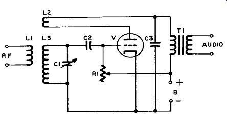
Figure 6.6 Regenerative Detector
Circuit Variations
A transistor may be used instead of a tube, and the audio output transformer is not required with headphones. As mentioned previously, L2 (which is sometimes called a "tickler" coil) may be movable to adjust the degree of coupling, in which case R1 may be replaced with a grid-leak resistor.
FM DISCRIMINATOR
With the schematic illustrated in Figure 6.7, we begin discussion of a group of circuits used in FM demodulation. The FM discriminator is not used much anymore because it requires a limiter (or noise suppression) preceding stage, whereas the ratio detector discussed next does not. But you may still meet with it (for example, one was shown in block form in the section on FM modulation in the previous section, in Figure 5.3).
Distinguishing Features
An IF transformer with an extra winding connected to a centertap on its secondary winding.
The opposite ends of the IF secondary connected to two diodes, both facing the same way.
Uses
FM radio receivers, TV sound sections and FM transmitters.
Detailed Analysis
L3 and C2 form a resonant circuit tuned to the intermediate frequency, which is 10.7 megahertz in an FM radio or 4.5 megahertz in TV. As you know, a resonant circuit seems like a pure resistance to a signal at its resonant frequency; that is to say, the current and voltage are in phase. But when the signal frequency is at some other frequency the resonant circuit acts like an inductor or a capacitor, depending upon whether the frequency is higher or lower.
T1 is constructed so that when the signal induced in L3 is exactly
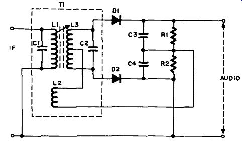
Figure 6.7 FM Discriminator
at the resonant frequency it will be 90 degrees different in phase from the signal in L1. The signal from L1 is also induced in L2,
but in this winding it is in phase.
The signal voltage in L2 combines with the signal voltage in each half of L3 to produce voltages at each end of L2 that are equal and opposite. When the upper end of L3 swings negative the lower end swings positive, and vice-versa.
When the frequency changes, due to modulation, the phase angles between the signal voltages in L3 and the signal voltage in L2 change accordingly, but in opposite directions. This results in unequal voltages at the opposite ends of L3.
When the upper end of L3 is positive, electrons low from the upper side of C3, and low to L3 through D1. At the same time the lower end of L3 is negative, but no current can low through D2. On the next half-cycle, when the voltage on the lower end of L3 swings in a positive direction, C4 becomes positively charged also.
The charging current consists of a train of pulses that, as we've just seen, charge C3 and C4 positively. Between pulses these capacitors do not have time to discharge through R1 and R2, since these resistors have a high value, so each becomes charged with the average peak voltage across the corresponding half of L3.
As long as the voltages on the opposite ends of L3 are equal the charges on C3 and C4 are equal. Likewise, the voltages at the two audio output terminals are equal, and therefore cancel each other out, so no output signal is produced.
But when the voltages on C3 and C4 differ, because of frequency modulation, unequal voltages appear at the output terminals. These alternate at the audio rate, because while the time-constants of C3-R1 and C4-R2 are such that they cannot follow the IF fluctuations in the signal voltage, they are designed to keep up with the audio modulation rate.
Circuit Variations
Some discriminators do not have a third winding on the IF trans former (L2). The centertap is connected to the upper end of L1 by means of a capacitor. A dual-diode vacuum tube may also be used instead of two semiconductors.
RATIO DETECTOR
There is a close similarity between the ratio detector (Figure 6.8) and the discriminator (Figure 6.7).
Distinguishing Features
An IF transformer with an extra winding connected to a centertap on its secondary winding.
The opposite ends of the secondary are connected to two diodes, facing in opposite directions.
Uses FM radio receivers and TV sound sections.
Detailed Analysis
As already mentioned, the ratio detector has replaced the discriminator because it does not require a preceding limiter (clipper) stage, so is more economical to produce.
The operation of the transformer T1 is the same, however, and need not be repeated here. But because D2’s polarity is reversed the voltages appearing on C3 and C4 are now in series.
A large capacitor C6 (usually an electrolytic of 5 microfarads) is connected in parallel with ...
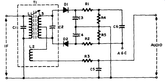
Figure 6.8 Ratio Detector
... both C3 and C4. Because of its large capacitance it damps out noise coming in with the signal.
The total voltage across C3 and C4 will equal the voltage across C6, which is the same as the total voltage across L3. However, as the signal swings back and forth in frequency, the ratio of the voltages on C3 and C4 will change with respect to each other. Consequently, the voltage at the point between them will fluctuate accordingly. A voltage difference varying at the audio rate will also exist between this point, which is connected to one side of the audio output, and the lower end of L2, which is connected to the other side of the audio output.
Circuit Variations
The lower end of L2 may be connected to the junction of C3 and C4, and the junction of R3 and R4 will then be omitted. The audio output signal will then be taken from these two junctions.
C3 and C4 may be omitted altogether if circuit capacitances are adequate.
C3, C4, R1, R2, R3 and R4 may be encapsulated together in an integrated circuit (IC). In the schematic they will be enclosed in dashed lines to indicate this.
GATED-BEAM FM DETECTOR
Figure 6.9 illustrates a typical gated-beam demodulator, the most economical FM detector, since it combines limiting, detection and audio amplification in one stage.
Distinguishing Features
A vacuum tube of special construction is used in this circuit, such as a 6BN6, 6JC6 or 6HZ6. In the schematic it has the same symbol as a pentode. Its three grids, reading from nearest the cathode, are named and connected as follows:
1. Limiter grid; IF input.
2. Accelerator grid: B-f- voltage.
3. Quadrature grid: parallel resonant circuit with quadrature coil.
Plate and cathode connections are as in other amplifiers.
Uses FM radio or TV sound demodulation stage.
Detailed Analysis
DC Subcircuit: In Figure 6.9 electron low is from B- via R1 to V.
From V’s plate it returns via R2 and R5 to B+. From the accelerator grid, current lows to B+ via R6.
AC Input Subcircuit: The IF signal is coupled from the previous stage by T1 to the limiter grid of V. The construction of this tube is such that it has a very steep characteristic curve. A swing of two or three volts is enough to drive it from saturation to cutoff (see Appendix for explanation of tube operation). The value of R1 is chosen so that the grid bias is about -4 volts, or midway on its characteristic curve.
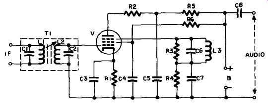
Figure 6.9 Gated Beam FM Detector
Consequently the action of the grid is to clip or limit the signal so that it has a constant amplitude, and noise and interference are removed.
The action of this grid is to switch the electron current from the cathode on and of in a series of lat-topped, steep-sided pulses, at the frequency of the IF signal. The electrons of these pulses are focused in a beam and accelerated by the second grid, which has a voltage of around 100 volts.
Quadrature Grid Subcircuit: Connected to the third grid is a resonant circuit consisting of C6 and L3. R3 and R4 are not really part of this circuit as their values are too high to have any loading effect on the circuit. They provide a path to ground for electrons collecting on the quadrature grid. (In some circuits they are omitted.) This resonant circuit is connected between the quadrature grid and the cathode (by way of C7 and C3). It is tuned to the IF resting frequency. In the absence of modulation a stream of electrons travels from the cathode to the plate in pulses, as previously explained, and some of the electrons in each pulse strike the quadrature grid, causing pulses of current to low in the resonant circuit. As this circuit is tuned to their frequency it oscillates, causing the voltage on the quadrature grid to swing back and forth. When it swings negatively it cuts off the low of electrons to the plate, but when positive it allows them to pass; so, like the limiter grid it also acts as a switch.
It is switching at the IF resting frequency, and as long as the limiter grid (in the absence of modulation) is doing the same the pulses of electrons passed by the two grids are at the same rate. However, the construction of the tube is such that the positive swings of the quadrature grid lag behind those of the limiter grid by 90 degrees.
It is like having two gates opening and closing in such a way that the second gate opens half way between the opening and closing of the first, and then closes half way between the closing and opening of the first. Electrons can only low when both gates are open, which is during the second half of each positive swing of the voltage on the limiter grid.
However, changes in frequency of the input signal caused by modulation change the amount by which the opening and closing of the " gates " overlap. The greater the overlap, the longer the burst of current, and vice-versa.
AC Output Subcircuit: These bursts of electrons arrive at the plate, and thence low through R2 to charge C5. This RC combination is what is called an integrating circuit (see section 8). Wider bursts mean more electrons, causing the voltage on C5 to build up; narrower bursts allow it to fall. Since the width of the bursts varies with the frequency, which in turn varies with the amplitude of the modulating signal, you can see that the voltage on C5 will rise and fall proportionately to the audio voltage with which the carrier was frequency modulated.
The tube is basically a voltage amplifier (see section 2) even though it also performs the limiting and demodulating functions just described.
Consequently the output is usually sufficient to dive an audio output stage, whereas the ratio detector requires an audio amplifier to follow it and drive the output stage. The discriminator not only requires an audio voltage amplifier to follow, but a limiter to precede it. (Limiters, or clippers, are covered in section 8.) Since the gated-beam tube enables limiting, demodulation and voltage amplification to be done in one stage it is easy to see why this is such a popular circuit in vacuum-tube FM receivers.
Circuit Variations
As mentioned before, R3 and R4 may be omitted, and the lower end of L3 may be connected directly to the low side of the circuit instead of via C7. Another variation sometimes met is the replacement of R1 with a variable resistor called a buzz control. This adjustment is provided to select the best bias point for the limiting grid, which is that which gives the least hissing sound with a weak signal.
The quadrature coil often has an adjustable slug which may also be adjusted for the strongest and clearest sound. The cathode bypass capacitor C3 is also omitted sometimes for the reasons explained in section 2 under degeneration.
The output signal is usually coupled through C8 to a volume control, as in other detectors.
ENVELOPE DETECTOR
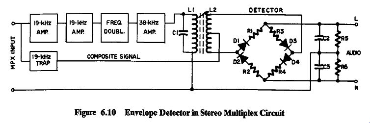
Figure 6.10 shows a switching-bridge detector, the most common form of envelope
detector. Envelope detectors are named so because they are used to detect the
envelope of the complex signal used in stereo FM broadcasting.
Distinguishing Features
A four-diode bridge follows an IF transformer, and has left- and right-channel outputs.
The detector is the final stage of a multiplex circuit, the rest of which is illustrated in block form in Figure 6.10. Each of the other circuits is discussed elsewhere in the guide.
Uses
Envelope detectors are used in stereo-multiplex circuits to separate the right and left channels of a stereo broadcast.
Figure 6.10
Detailed Analysis
FM stereo broadcasts must be receivable by monaural equipment also, therefore the audio from both channels is mixed together at the station in what is known as the L + R signal. Thus a single-channel set receives both channels of a stereo transmission. This is what is meant by the expression "compatible FM stereo." To provide for two-channel reception an additional audio signal is generated at the transmitter by splitting the two channels, so that there are two right- and two left-channel signals. Then the phase of the second right-channel signal is inverted before mixing it with the second left-channel signal. There are now an L + R and an L - R signal, the L - R representing the difference between the two channels.
Both signals are used to modulate the carrier, but in order to keep them separated the L - R signal is first made to modulate a 38 kilohertz subcarrier, using AM. Sidebands are produced above and below this frequency over the range from 23 kilohertz to 53 kilohertz.
This 3 8-kilohertz signal is then used to modulate the carrier along with the L + R audio signal. However, so as to improve the signal-to noise ratio, the 38-kilohertz carrier is suppressed; consequently the signal received by the FM receiver consists of the FM carrier, modulated by the audio and the 38-kilohertz sidebands only.
In order to recover the L - R signal it is necessary to re-insert the 38-kilohertz subcarrier, which is done in the multiplex circuit of the receiver, or " stereo adapter " as it was called when purchased separately.
A locally generated signal by itself will not do, because it must have exactly the same frequency and phase as the original. Therefore a pilot signal of 19 kilohertz is also transmitted. This doesn't affect the signal-to-noise ratio, because it is transmitted in the unused space between the maximum audio (L + R) frequency of 15 kilohertz and the lower limit of the lower L - R sideband, which as you already saw is 23 kilohertz. This pilot is also of lower amplitude than the subcarrier before suppression.
The output of the FM detector-probably a ratio detector-contains the L + R audio signal, the L - R 38-kilohertz sidebands and the 19-kilohertz pilot. In a monaural receiver the 19-kilohertz and 38 kilohertz signal cannot pass through the audio output stages to the speaker, therefore only the L -1- R audio would be heard.
But in a stereo set the composite audio output of the ratio detector will be routed through a stereo-multiplex circuit similar to that in Figure 6.10, where the 19-kilohertz pilot signal is extracted and amplified by IF amplifier stages similar to those described in section 2. It is then applied to a frequency-doubler, which reconstitutes it as the original 38-kilohertz carrier. (Frequency-doubling is discussed in section Meanwhile the composite audio signal is fed to the secondary of the 38-kilohertz IF transformer in such a way that the L - R sidebands are recombined with their carrier.
The diodes in the detector Bridge are arranged so that D1 and D3 demodulate the 38-kilohertz signal when it swings so that the upper end of L2 is negative, and D2 and D4 demodulate it when the lower end of L2 is negative. This gives demodulated audio from D1 and D3 which is L - R, while that from D2 and D4 is of opposite phase, or -L + R.
These combine algebraically with the L + R signal, which is present also, of course, as follows:
The left and right channels then pass through separate audio amplifiers to the left- and right-channel speakers.
Circuit Variations
The circuit we have just discussed uses four diodes in what is called a switching bridge because it switches back and forth as the 38 kilohertz carrier swings back and forth between its positive and negative peaks. In other words, it samples each channel alternately. This can also be done with only two diodes, operating alternately to charge capacitors as in the discriminator, except that the audio signals appearing on the capacitors are now for separate channels.
A rather more complex circuit, using bandpass filters (see section 8), separates the output of the FM detector into its three components; the L 4- R signal (up to 15 kilohertz); the 19-kilohertz pilot signal; and the L - R signal (23 to 53 kilohertz). In this circuit, which is called a bandpass and matrix circuit, a 19-kilohertz local oscillator generates a signal which is synchronized by the 19-kilohertz pilot (as explained in section 4). This is then doubled and re-inserted to reconstitute the original L - R signal. This signal is then demodulated, using two diodes as just described, to give the L - R and -L + R signals, which are then combined with the L + R signal in an arrangement of capacitors and resistors called a matrix, which is to ensure that they are combined in the right proportions.
DE-EMPHASIS
In section 5 you saw that in FM transmission it was necessary to use pre-emphasis to obtain a more favorable signal-to-noise ratio. This resulted in the higher audio frequencies being transmitted with greater power than the lower. In the receiver it is necessary to restore the proper proportion between the higher and lower frequencies, and this is done by de-emphasis.
In Figure 6.8 de-emphasis is performed by R3 and C5, which have a time-constant corresponding to that of the pre-emphasis circuit in the transmitter. Such a high-frequency attenuation circuit is similar in operation to the bass control of section 2, but without the variable resistor.
While de-emphasis must take place between the detector and the audio amplifier following it, it cannot come before a stereo-multiplex circuit, since it would attenuate the 19-kilohertz pilot and the 38 kilohertz sidebands.
Consequently it will always be placed in the output of a multiplex unit. However, sets designed to receive stereo broadcasts usually have a function switch with a monaural position which bypasses the multiplexer when not required. In this case the FM detector has two outputs, one for stereo without de-emphasis, and one for monaural with de-emphasis, and the switch selects the appropriate output.
SYNCHRONOUS DETECTOR
In the previous section you saw how phase modulation as used in color TV was accomplished by using a pair of doubly balanced modulators. PM demodulation is the same process in reverse. Figure 6.11 shows a synchronous detector using a pentode. Two of these are required to extract the signal’s two component vectors, just as two modulators were required to combine them.
Distinguishing Features
The 3.58-megahertz reference signal is applied to the No. 3 grid of the pentode, and the modulated color subcarrier (chroma) is applied to the control grid. In the output appears a filter circuit (L1-C1) to eliminate the 3.58-megahertz subcarrier, which is no longer required.
Uses
Color television reception.
Detailed Analysis
DC Subcircuit: In Figure 6.11 electron low is from B- via R2 to V1. From the plate of V1 current returns via L1, R4 and L2 to B+.
From V1’s screen grid it reaches B+ through R3.
AC Input Subcircuit: The modulated subcarrier (chroma) is applied across R1, the color gain control, which is adjusted to give the desired signal on the control grid. This is biased to avoid complete cutoff, so that the whole color signal is amplified.
The 3.58-megahertz reference signal, synchronized with the transmitter, is applied to the No. 3 (suppressor) grid. A negative voltage on this grid will cut the tube off completely. In a receiver designed for I and Q color signals the reference signal for the I demodulator must be phase-shifted 57° before reaching the grid. That for the Q signal must be 90° more, as you saw in the previous section. However, many receivers use different vectors for which other phase angles are required.
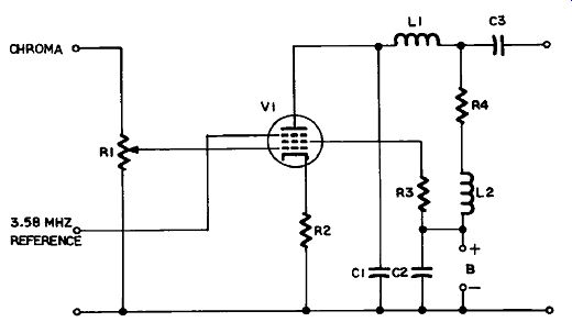
Figure 6.11 Synchronous Detector
This does not alter the principle of operation of this circuit.
AC Output Subcircuit: V1 can only conduct when the suppressor grid is not negative. During each positive half-cycle of the 3.58-megahertz reference signal, current will low in proportion to the voltage on the control grid. The greatest current will low when a positive half-cycle of the color signal on the control grid coincides with a positive half-cycle of the reference signal on the suppressor grid. This happens when both signals are in phase.
However, the phase angle of the color signal is constantly changing as the color information changes. Therefore the direct current out of V1 will consist of a series of pulses at 3.58 megahertz which will vary in width and amplitude according to the amount of overlap between the two signals. This action is similar to that of the gated-beam tube previously discussed in this section.
Since the reference signal of each of these demodulators is 90° different from the other, their output will consist of the two vectors added at the transmitter. In each demodulator these pulses are integrated and smoothed by C1 and L1, and coupled through C3 to the next circuit.
Circuit Variations
Demodulators sometimes employ two gated-beam tubes of the type used in FM detection instead of pentodes. Dual-beam-deflection tubes have been developed (such as the 6JH8 ) to give a push-pull action.
Transistors can replace tubes in essentially similar circuits. Diodes may also be used in circuits resembling the ratio detector already discussed (see Figure 6.8). Two pairs of diodes are required, but they share a center-tapped transformer that supplies reference signals at 90° phase difference. The diodes conduct according to the phase and amplitude of the color signal.
------------------
-------------------