26. Circuit Classifications
From the standpoint of circuit design and the selection of crystal units for use as frequency control devices, crystal oscillator circuits may be conveniently classified as parallel resonant or series resonant.
The parallel resonant circuit is generally favored for use with crystals operating in their fundamental mode (lowest frequency to which the crystal can resonate) , while series resonant arrangements are preferred when the crystal is to produce overtones or harmonics.
A sub-classification often encountered is that which differentiates between straightforward triode oscillators and the electron coupled type, which makes use of the screen grid element of a pentode to achieve increased stabilization of frequency.
This Section will be confined to parallel resonant circuitry, both triode and electron-coupled, currently in use by amateurs, commercial communications companies, and the military. Series resonant circuits employing overtone crystals and other special forms of oscillators will be discussed in Section 5.
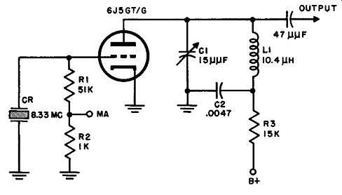
Fig. 23. Basic Miller oscillator circuit.
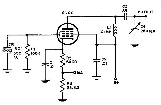
Fig. 24. Beam-tube Miller oscillator circuit.
27. Standard Miller Oscillator
The fundamental circuit of this oscillator was discussed in Pars. 8 through 11 in connection with Figs. 6 through 9. A practical circuit using a 6J5GT /G is shown in Fig. 23. It is readily evident from a comparison of this illustration with Fig. 6 that the circuits are identical except for the addition of two resistors, R2 and R3. R2, in series with the grid leak resistor, carries the rectified grid current and develops a small voltage drop proportional to the excitation. An external milliammeter may be switched to the "MA" test point and ground to measure the amplitude of the excitation voltage without disturbing the circuit operation in any way. R2 is very small in comparison to R1 and therefore has negligible effect upon the grid leak bias. However, milliammeter resistance is small compared to R2, so virtually all the current goes through the meter and the reading is correct.
R3 is a series dropping resistor inserted to reduce the plate voltage on the 6J5GT /G. This is the usual procedure when a power supply, common to other higher-powered stages in a transmitter, provides an output voltage that would be excessive if applied directly to the oscillator.
28. Miller Oscillator Using Screen Grid Tube
A screen grid tube--specifically a pentode or beam-power tube--offers a number of advantages as a crystal oscillator. The higher power sensitivity of a pentode makes possible greater output from the oscillator with the same or less crystal excitation, hence the crystal runs cooler; furthermore, pentodes of the well-shielded variety (6AC7, 6AG7, etc.) have so little capacitance between plate and control grid that it is almost impossible to overdrive the crystal in the Miller circuit. As a matter of fact, it is often necessary to add a small capacitance from plate to grid to form a second feedback loop to maintain oscillation. The circuit given in Fig. 24 does not need this additional capacitance because it uses a 6V6G, which has a high enough grid-plate capacitance.
The voltage applied to the plate and screen of the oscillator tube is relatively high (300 to 400 volts). Accordingly, for safety, cathode bias is provided in the form of a voltage drop across R2, a 500-ohm resistor. R3 serves the same purpose as in the oscillator shown in Fig. 23--that of providing a test point for current measurement; here the cathode current, rather than the rectified grid current, may be read by switching the external milliammeter to the junction of R2 and R3 and to ground. Capacitor C2 keeps the screen grid of the 6V6G at ground potential for r-f. C3, a comparatively large capacitor of low reactance at radio frequencies, passes r-f to complete the tuned circuit L1-C4 but keeps d-c voltage off capacitor C4. This allows grounding of the rotor plates of C4, which is the tuning capacitor. C1 is the cathode bypass capacitor, which provides a low impedance path for the plate circuit r-f current to return to the cathode.
29. Electron-Coupled Miller Oscillator
In this type of circuit, the screen grid of a pentode or beam power tube serves as the plate, and the plate of the tube becomes an output electrode. Since the potential of the screen grid varies with the radio-frequency energy generated by the oscillations in the screen tank, the electron stream that moves through the screen grid to the plate is modulated at the frequency of the crystal. The plate tank circuit, being resonant to the crystal frequency, oscillates as a result of the properly timed r-f pulses that reach it through this modulation process. The advantage of an electron-coupled crystal oscillator lies in the fact that the output circuit is completely isolated, capacitively, from the crystal circuit, being coupled only through the modulated electron stream. Thus, changes in output loading have little effect on crystal loading.
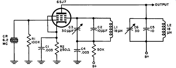
Fig. 25. Electron-coupled crystal oscillator.
Figure 25 shows the circuit of a practical electron-coupled Miller crystal oscillator using a 6SJ7 pentode. Note the two tuned circuits and the safety bias resistor, R2. L1, C3, and C2 comprise the screen tank while the plate tank is made up of L2, C6, and C5.
Fixed capacitors C2 and C5, which form a part of the two tuning networks, make it possible to use smaller variable capacitors (C3 and C6). This is always an advantage in that the tuning becomes broader and easier to handle.
30. The Fundamental Pierce Oscillator
The Pierce crystal oscillator has gained widespread acknowledgment as one having excellent frequency stability, great versatility, and extreme simplicity of construction. Although its output is not as great as that of a Miller oscillator using the same crystal unit, the feature of "tankless" oscillation makes it very easy to use with a multiplicity of crystals since it does not require retuning every time the crystal is changed.
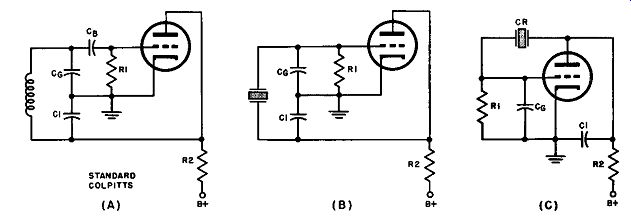
Fig. 26. (A) Colpitts oscillator circuit, self-excited, (B) crystal controlled
Colpitts circuit, which is the same as the Pierce circuit, (C) regular form
of Pierce oscillator circuit.
The drawings in Fig. 26 (A) and (B) show the equivalence of the Pierce crystal oscillator and the standard Colpitts self-excited type. It will be recalled that the Colpitts oscillator sustains oscillations by virtue of the split tank capacitor Cg and Cl by means of which plate-to-grid feedback is achieved. Further examination of the circuit shows that capacitor Cb, necessary in the Colpitts to block high voltage d-c from the grid of the vacuum tube, is not required in the Pierce circuit because of the dielectric properties of the crystal and holder.
Otherwise, the circuits are identical, with the crystal unit re placing the tuning inductance of the Colpitts. For those who are accustomed to seeing the Pierce oscillator drawn somewhat differently, the conventional schematic layout is illustrated in Fig. 26 (C) . The use of a load resistor (R2) makes the Pierce oscillator wide in frequency response so that it may be used with various crystals covering a large range; for greater activity and output where wide response is not a factor, R2 should be replaced by an r-f choke of the inductance required for the particular frequency.
Some modern adaptations of the Pierce crystal oscillator are discussed and illustrated in the paragraphs which follow.
31. Practical Triode Pierce Circuit
The Pierce modification in Fig. 27 differs from the basic circuit in several details: the grid capacitor (CJ) is variable so that the amount of crystal excitation may be adjusted for optimum operation; a small amount of safety bias is introduced by the voltage drop across R2 and the consequent d-c charge in CJ; and the crystal is coupled to the plate via C2 (.01 mfd) rather than being directly connected from grid to plate. This capacitor serves a double purpose in this case because is removes d-c from the crystal holder and enables the output of the oscillator to be coupled to the next stage without additional capacitance. The 2.5-mh r-f choke used as a load impedance in this oscillator improves the output but limits the oscillator to a narrower range of crystal frequencies. This particular circuit is used as a master oscillator in a transmitter de signed to cover the range between 2000 and 4000 kHz; thus, the width of its coverage is sufficiently small to permit the use of the r-f choke rather than a load resistor.
32. Screen-grid Pierce Oscillator
The oscillator given in Fig. 28 is typical of many master oscillators being used in specialized military equipment on the lower radio frequencies. The Pierce circuitry is evident upon inspection of the schematic, the departures from the fundamental arrangement being due largely to the use of a screen grid tube rather than a triode.
Fig. 26. (A) Colpitts oscillator circuit, self-excited, (B) crystal controlled
Colpitts circuit, which is the same as the Pierce circuit, (C) regular form
of Pierce oscillator circuit.
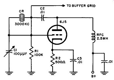
Fig. 27. Modified Pierce oscillator circuit.
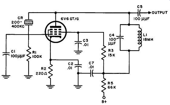
Fig. 28. Screen grid Pierce oscillator circuit.
The additional components are: C3, a capacitor that keeps the screen grid at r-f ground potential; R3, a screen dropping resistor to bring the voltage to the rated value for this tube; R5 and C7, a decoupling network intended to isolate the oscillator from other stages operated by the same power supply; and the nonadjustable tank circuit comprising C4 and L1, chosen to offer a relatively high impedance over the range of 200 to 400 kHz. At these low frequencies a parallel resonant circuit used as a plate load is a more effective method of obtaining a high plate impedance than an r-f choke or a resistor.
33. Electron-Coupled Crystal Oscillator
The electron-coupled crystal oscillator shown in Fig. 29 is an adaptation of the grounded-plate Colpitts circuit to crystal control and electron-coupling, with the crystal replacing the untapped Colpitts tuning inductance. Capacitor C1 effectively grounds the screen grid and, since this electrode serves as the plate of the oscillator, it may be referred to as a grounded-plate circuit. The amount of crystal excitation is a function of the ratio C1/C2, C1 being made variable so that the excitation may be adjusted for best performance.
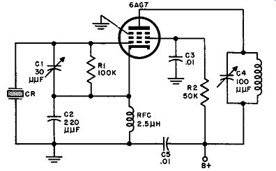
Fig. 29. Colpitts crystal oscillator circuit in electron coupled form.
It is desirable always to ground one of the crystal electrodes. But, if that is done in this particular circuit, the ground must be moved from the cathode, which then must operate at r-f potential above ground. An additional component-the r-f choke-must be connected between the cathode and ground to provide a d-c return path to the cathode for the plate current, without short-circuiting the cathode to ground for r-f. It may be observed by referring to Fig. 26 (A) that an r-f choke is unnecessary if the cathode is grounded, but under the circumstances shown in Fig. 29, the d-c plate path must be completed by a device having high r-f impedance, hence the use of the choke.
The 6AG 7 is an excellently shielded tube, internally; this makes for minimum reaction between output and input circuits and lends greater stability to the crystal oscillator. In this circuit again, the electron stream is modulated by the oscillation frequency and the plate circuit is, therefore, electron coupled to the oscillatory section.
34. QUIZ
1. What single major factor of circuit design determines the selection of a parallel resonant or series resonant crystal oscillator?
2. Draw a circuit of a standard Miller oscillator using a 6J5GT. Assign values to the component parts and explain the purpose of each component in the diagram.
3. What advantages might be gained by replacing the triode of question 2 with a pentode? Are any other circuit modifications necessary?
4. Draw a typical circuit for the "Pierce" crystal oscillator.
5. Give the equivalent circuit for the diagram above.
6. Draw the electron coupled Miller oscillator and explain its operation.
7. Why is grid capacitor C1 of Fig. 27 variable?
8. What are the two functions of C2 in Fig. 27?.
9. Draw the diagram of an electron-coupled crystal oscillator and explain its operation.
10. In the diagram of question 9 an r-f choke is usually inserted between cathode and ground. Explain why this is necessary.