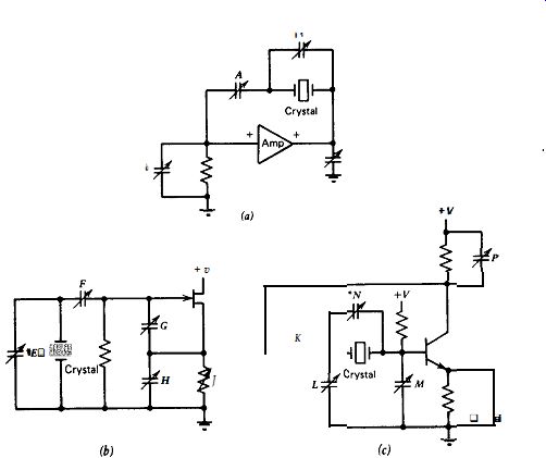
Figure 8.1. Capacitor locations for frequency trimming in three popular oscillator circuits. *Indicates locations that are not recommended. (a) Series resonant, (b) Colpitts, and (c) Pierce.
| Home | Audio mag. | Stereo Review mag. | High Fidelity mag. | AE/AA mag. |
A certain amount of +/- frequency tolerance must be allowed in manufacturing crystals to a specific frequency. In addition, either a reactive load on the crystal or a phase shift in the oscillator's amplifier will move the actual oscillation frequency slightly up or down from the crystal's own internal series-resonant value. To tune a crystal oscillator to a specific frequency, it is necessary to adjust the phase shift somewhere in the amplifier loop. This can be done by inserting either a variable inductor or a variable capacitor in the circuit, or by varying the resistance in an already existing RC or RL phase-shifting network. To raise the frequency, a phase lead is added to the amplifier loop, or an existing phase lag is decreased. To lower the frequency, a phase lag is added to the amplifier loop, or an existing phase lag is increased. In a harmonic oscillator, the frequency can be trimmed both up and down by varying the tuning of the circuit's LC tank.
The most common method of frequency trimming is putting a variable capacitor either in series or in parallel with the crystal. Figure 8.1 shows a variety of resistive and capacitive trimmer locations for three popular oscillator circuits. Table 8.1 shows the relative frequency sensitivity of most of these locations. Using an inductor rather than a capacitor will reverse the direction of frequency shift.
Placing a capacitor or an inductor directly in parallel with the crystal for frequency trimming purposes is not recommended, since it tends to short out the crystal and reduce the crystal's control over the circuit.
Frequency trimming capacitors or inductors are not used in oscillator circuits in this guide for reasons of simplicity and to make the circuits easier to understand.
Figure 8.1. Capacitor locations for frequency trimming in three popular oscillator
circuits. *Indicates locations that are not recommended. (a) Series resonant,
(b) Colpitts, and (c) Pierce.
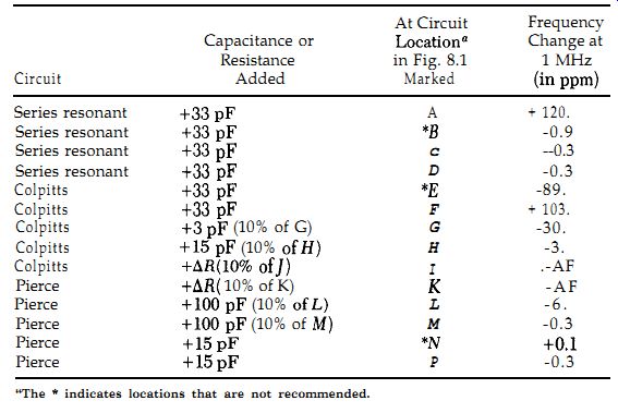
TABLE 8.1: Relative Frequency Sensitivity of Various Condenser Trimmer Locations at 1 MHz
-- The * indicates locations that are not recommended.