Counters made with cascaded toggles
By J. A. "Sam" Wilson, CET
Toggles in digital electronics, a toggle is a frequency divider (that is, the output repetition rate is half that of the input). A 1000-Hz input produces a 500 Hz output, for example.
You can make J-K flip flops toggle, by connecting the set, clear, J, and K pins to a permanent high (such as the positive supply voltage), and then applying an input signal to the clock terminal. Frequency divided output appears at the Q pin, and an inverted Q signal at the terminal.
To simplify toggle diagrams, the J-K flip flop symbol of Figure 1B often is used.
Also, notice that the toggle input is drawn at the right. This is contrary to the usual practice of showing inputs at the left and outputs at the right. But, it is done here in anticipation of the use of toggles in counter circuits, where the count for the least-significant number is placed at the extreme right. Other numbers are placed to the left, in consecutive order.
An experiment last month demonstrated the ability of toggles to divide a frequency, and to show that two toggles can be cascaded in series to produce one-fourth frequency.
The next experiment shows how toggles can be made to count in binary fashion.
Experiment #1
Wire the circuit of Figure 2. If possible, arrange the first flip flop and its LED at the right, and the second flip flop at the left as shown. Triggering occurs when the input waveform goes low, as is generally true of Transistor-Transistor Logic (TTL). Arrows on the waveform drawings show points where the two flip flops are triggered.
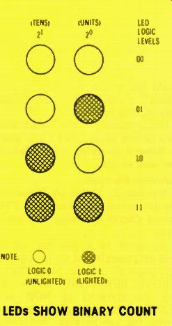
Figure 3 shows the LED patterns for four binary numbers produced by the Figure 2 circuit. Shaded circles symbolize lighted LEDs (highs), and empty circles indicate unlighted LEDs (lows). The two columns are labeled with both the binary and decimal equivalent designations. More columns can be added at the left to permit counting to higher numbers.
(Four columns allow counting up to 15.)
These four possible conditions of the two LEDs can indicate four separate combinations of highs and lows, as shown in the LED Logic Levels column. According to one system of binary counting, the right-column logic level has a value of 1, while the next to the left has a value of 2 (the next two places have values of 4 and 8, as we will find out later). Therefore, the 00 binary readout equals 0 in decimal, 01 equals 1, 10 equals 2, and 11 equals 3. Thus, two columns permit counting from decimal 0 to 3.
Notice in Figure 4, however, that the simple counter of Figure 2 produces four consecutive combinations of logic levels and then repeats them again and again (until the power is removed). Such continuous repeating usually is not desirable. A method is needed for starting and stopping the count.
The next experiment describes one such method.
Experiment #2
The count of a counting circuit never should be stopped by eliminating the clock (or input) signal.
With flip flops wired as toggles (see Figure 1), change the J or K pin (or both) from logic 1 to logic 0, to stop the count at any point.
A manually-operated start/stop circuit is shown in Figure 5, where the K-pin logic state of both flip flops is determined by the output of a NAND. Both inputs of a NAND must have the same logic level to produce a low at the output. One input is connected to a high from the power supply; therefore the NAND output will go high (allowing the toggles to count) when the other input is switched low (to ground). Or, it will have low output (stopping the count) when the other input is switched high (to supply voltage). Of course, the count could be stopped by switching J, both J and K, set, or clear to a low condition.
Wire the circuit of Figure 5 and verify the operation, according to the results just described.

Figure 1 (A) Connect a J-K flip flop this way to make it toggle (act as
a frequency divider). (B) Many toggled flip flops use this simplified symbol.
Notice the inputs are at the right and the outputs at the left, to make the counting operation more clear.

Figure 2 Two consecutive toggles with LED readouts can function as a binary
counter for decimal numbers 0 through 3. Arrows on the waveforms show where
the TTL triggering occur. Each negative edge of the input pulses forces the
flip flop to reverse the prior output state.
Experiment #3:
When a counter is RESET, all digits are returned to the zero state.
In other words, the counter is CLEARED.
During a count, the CLR (clear) terminal of a flip flop in a 7476 IC normally is held at logic 1. Switching the CLR terminal to logic 0 causes the flip flop to change to a low output condition.

Figure 3 Any lighted LED in Figure 2 indicates a high, and an unlighted
one shows a low. A high in the left column has a decimal value of 2, and
a high in the right column has a decimal value of 1. Can you obtain the decimal
equivalents of these four binary counts?

Figure 4 These are the waveforms of Figure 2 with the binary and decimal
values added.
MANUAL STOP OF COUNTING

Figure 5 A low at the K terminals of both toggles stops the count, and freezes
the logic levels to the last ones before the stop. A high at the K terminals
permits the circuit to count continuously. A NAND is used to change the K
terminal logic state.

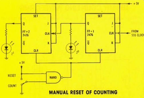
Figure 6 shows a manually operated reset circuit, one that uses a NAND to
switch the CLR terminal state. The operation of the NAND is identical to
the one in Figure 5, except the switch is labeled "RESET" when
the second NAND input is high, and "COUNT" when the input is low.
When the switch is at the RESET position, the CLR pin is low (grounded), and both flip flops change to the low condition with both LEDs off.
Wire the circuit of Figure 6, and verify that the action is as predicted.
Note: not all flip flops require a logic 0 for clear or reset. In each case, consult the manufacturer's truth table to find the logic levels that are needed for the various kinds of operation.
Letters
Usually, I reply by personal letter to any correspondence that's connected with the industrial series. However, some of the letters should be shared with you readers.
Publications wanted Mr. Alfred Jutkiewicz of Chelsea, Massachusetts asks, "In your list of publications do you have any about Programmable Logic Controllers (PLC) and ladder diagrams? I want to understand the theory and practical side of them." Because I don't have a list of publications about that subject (or any subject), I'm hoping one of the readers can help. Send any information in care of ELECTRONIC SERVICING, and I'll forward it to Mr. Jutkiewicz.
Mercury-Vapor Lights
Mr. Harold A. Jones, of Baltimore, Maryland writes that the mercury - vapor ceiling - mounted lights in his company buildings never are turned off, even when they are not needed (during daylight hours). There are 60 or 70 lights in each of several buildings. The reason given by company representatives is that turning them on and off each day would shorten the life of the bulbs.
Mr. Jones questions the economy of this method, and believes there might be a way of keeping the lamps in a stand-by condition when they are not needed.
Unfortunately, I can't find any data on this subject, but I'll be glad to forward anything other readers can send to me.
Switching flip flops
Reader Z. Daku of Prescott, Ontario wants clarification of TTL versus CMOS switching characteristics.
An error in a previous article probably contributed to the request.
On page 57 of the May ELECTRONIC SERVICING, the switching characteristics of NOR and NAND latches were given correctly under the sub-heading "Switching NOR latches" until the middle of the third paragraph from the bottom of the page where this statement appeared: "Therefore, TTL flip flops switch during the leading edge of input pulses, while CMOS flip flops switch on the trailing edge of input pulses." That statement has the facts reversed.
NAND TTL flip flops change output state from the trailing edges (transition from high to low) of input pulses, while CMOS NOR flip flops change output state from the leading edges (rising level from low to high) of input pulses. The original illustration (Figure 14 of that issue) was correct.

Figure 6 Changing the CLR (clear) terminals of both toggles from high to
low stops the count and resets the toggle outputs to logic zero. A NAND does
the actual reversing of the CLR logic level.

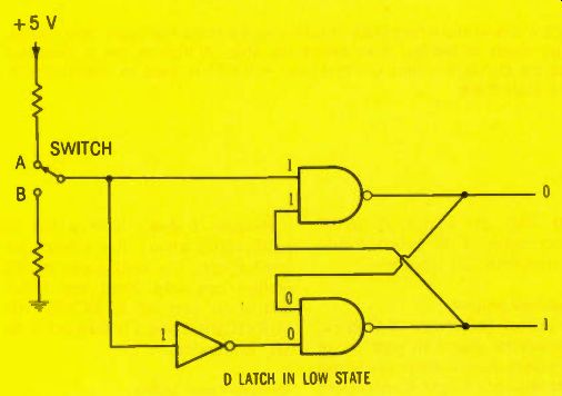
Figure 7 Logic levels at all terminals of the NANDs and the NOT used as
a D latch are shown, to illustrate the wrong answer given before.
Trouble about a Troubleshooting Question
Many readers objected to my answer for Troubleshooting Question #5 on page 67 of the April ELECTRONIC SERVICING. The schematic is given again in Figure 7, along with the logic levels at each point, which prove the D-type flip flop to be in a low output condition (not high, as stated before). Would you believe that I was merely testing you to see if you really were doing the trouble shooting questions? I hope so, for my secretary ordered me to stop blaming everything on typing errors.
Editors Note:
Sam, you should use the same excuse we do when mistakes happen; blame the type setters!
(adapted from: Electronic Servicing magazine, Aug. 1978)
Next: Sept. 1978
Prev: Jul. 1978
Also see: Sam Wilson's Technical Notebook