295 RF MODULE FOR INDOOR UNIT
The series of articles on satellite TV reception, started in the September 1986 issue of Elektor Electronics, has met a great deal of interest from our readers. Many have successfully ventured out into the world of centimeter waves and SHF construction methods, and are proud to watch the pictures produced by a home-made Indoor Unit.
The construction and alignment of the RF input stage and the local oscillators is undoubtedly the most difficult phase of the project. However, an at tractive alternative is now available for those constructors hesitant about their skills in dealing with very high frequency components and techniques.
The Type HL ECS51 is a ready-made, tunable, 950 1750 MHz to 480 MHz converter of Taiwanese origin, and is eminently suitable for taking over the previously mentioned functions on the RF board (Type EPS 86082-1). The module is tuned with a voltage between 0 and 20 V, and requires no band (H/L) switch. It has a connection for applying the LNB supply voltage, which is carried to the LNB via the downlead cable as usual. The module itself is conveniently fed from 12 VDC, and consumes about 100 mA. Its RF input is a Type F socket.
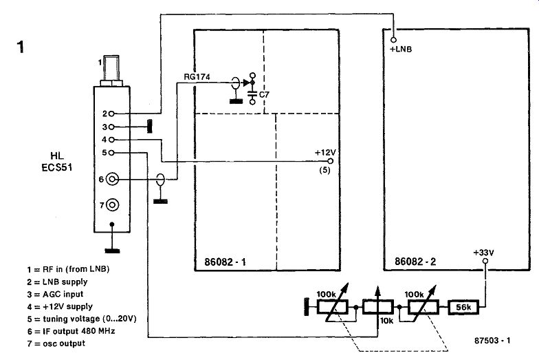
Figure 1 shows the ready connection of the module to the RF board in the IDU. Module pin 3 is the AGC input, which is grounded here to achieve maximum gain. A 56 k4 resistor is fitted in series with the existing + 33 V tuning voltage rail to en sure the correct maximum input to pin 5. The IF output on the module accepts a common phono plug, to which a short length of thin (RG174) coax cable is soldered for connecting to the short track between pin 3 and 4 of MX, on the RF board.
Coupling capacitor C7 should be left in place, but MX1, the RF input stage, and both local oscillators may be omitted, since the module takes over their function. In case the RF board is already complete, it is recommended to remove MX1, R3 and band selector S1. The screen between the RF input stage and the local oscillators may also be omitted, but not the remaining screens on the board.
Before aligning the "modular" Indoor Unit, the intermediate frequency requires lowering from 610 to 480 MHz. The VCO in the SL1451 PLL can be tuned to the new center frequency by increasing the inductance of L8. This is easiest to do by making a new inductor as shown in Fig. 2. Use about 5 cm of silver plated, 0 1 mm (SWG20) wire to make the single turn inductor, ensuring that the underside of it is just above the PCB surface.
--------
1 = RF in (from LNB)
2 = LNB supply
3 = AGC input
4 = +12V supply
5 = tuning voltage (0...20V)
6 = IF output 480 MHz
7 = OSC output
The alignment procedure of the module-based Indoor Unit is essentially identical to that set forth on page 54 in Part 2 of (1). The reference there to TV channel 36 (600 MHz) should then be read as TV channel 21/22 (approx. 480 MHz). The IF band-filters can be tuned to the new frequency when the respective trimmers are set for nearly maximum capacitance.
Finally, a note on the results obtained with the module in combination with the RF board as described here: the original, completed, and properly aligned RF board with the BFG65, local oscillators, and MX, fitted gives a slightly better performance when relatively weak signals (C/Ns 12 dB) are being received. This is mainly due to its noise figure being lower than that of the HL ECS51 module, which is specified for no less than 15 dB in this respect. None the less, the module gives good results with relatively strong input signals.
Literature reference:
(1) Indoor Unit for Satellite TV Reception Parts 1-3; Elektor Electronics, October 1986 and following issues.

-----
296 RGB-TO-MONOCHROME VIDEO COMBINER
This circuit offers impeccable monochrome images when driven by the digital RGB and sync signals of a high-resolution graphics card such as the one featured in Elektor Electronics, issues from November 1985 to March 1986.
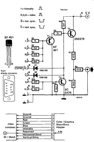
Transistor T2 in the video combiner/buffer ensures a short-circuit proof, 75 ohm impedance monochrome and composite video signal with an rms value of about 1V, as usual for connection to a monitor. The combination of a PNP and an NPN transistor, T1 and T2 respectively, for amplification and combination of video and sync typically exhibits a good response to the fast rise and fall times of these signals, and thus enables sufficient picture definition in the case of, for instance, text presentation at 80 characters per line, or high-resolution graphics applications.
---------
The input circuit arrangement with T1 and the mixer resistors is a D/A converter in its most rudimentary form; the R, G, B, and I signals are applied to resistors at values that correspond to the luminance percentage of each basic color, to the effect that any color shade is represented as one of 16 shades of grey on the monochrome monitor.
Where this is desirable, the intensity bit resistor may be replaced with a 2k5 preset; this enables setting the intensity ratio. In case the present combiner is used with a video interface that merely supplies a video and sync signal, or merely RGB signals, the unused inputs may simply be left open.
The sync signals are combined with the video signal at the base of T2; depending on the system setup, the sync input may have to be slightly modified.
Where an inverted CSYNC (composite sync) signal is available, as in the case of the Elektor Electronics graphics card, all parts relevant to the sync inputs may be dispensed with, except for Di. Resistors R5 and R6 determine the black level of the composite video signal, to which the sync component is added by Di, which is capable of lowering the base voltage of T2 to a value, lower than the black level.
Diode D2 allows separate, inverted sync signals to be applied to the combiner, and T3, R10, R11 and R12 may be added for video systems that output a positive-going, separate sync.
The combiner may also be used with the video interface incorporated in the IBM PC (see Elektor Electronics, May 1985 issue); if this computer is equipped with a monochrome video board, the sync mixer only requires D2, R11, R12, and T3. The IBM color board requires the addition of Rio, whereas D2 may be left out. Figure 2 shows how the video combiner is typically connected to the IBM color board. Note the use of the 'reserved' line (7) for the + 5V supply voltage of the combiner circuit.
297 SCART SWITCH
This circuit is not really a technical novelty, but it has its practical uses. If, for instance, it is desired to connect a video recorder AND a computer permanently to the SCARF socket at the back of a modern television set, it will be found that that is impossible. All that can be done is to connect either the video recorder or the computer. But the proposed SCART switch offers a solution to this problem.
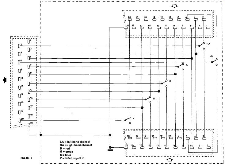
The switch is constructed from a small (110 x 60 x 30 mm) metal case, a six-pole change over switch, two SCART sockets, one SCART plug, and a length of screened coaxial cable. Suitable holes should be provided in the case to receive the two sockets, a cable outlet, and the switch. The various components are connected together as shown in the accompanying diagram. The SCART plug is connected at the free end of the cable, which should not be longer than 1 meter. The connections to the sockets and plug are also identified in the table.
-----
The completed switch should find a home beside, under, or on top of the TV set: the SCARF plug is inserted into the SCARF socket at the back of the set. The two SCA' sockets on the case are then used to receive the computer and video recorder respectively. From then on, it is a simple matter of switching between recorder and computer!

------- SCART connector
298 SYNCHRONIZATION SEPARATOR I
Many monitors have separate inputs for the line (horizontal) and field synchronization pulses. If your computer only provides composite sync pulses, the circuit described here makes it possible to split the composite sync signal, CSYNC, into proper line, HS, and field, VS, pulses.
It is possible to feed the CSYNC as line sync pulses direct to the monitor, which is the reason that the CSYNC input is connected direct to the HS output terminal.
To derive the field sync pulses from the composite signal, a dual retriggerable monostable type 74LS123 is needed. The first mono period is slightly longer than the distance between two line sync pulses. As the monostable is retriggered by each line sync pulse, it only resets in the absence of a line sync pulse, that is, at the onset of a blanking inter val. The first monostable then triggers the second, which generates a VS pulse at its ohm output. When the second mono period has lapsed, the first monostable has already been provided with more line sync pulses, so that monostable 2 is not triggered again until the next blanked interval. The overall result is that all line sync pulses are sup pressed, while monostable 2 provides field sync pulses.

------
299 SYNCHRONIZATION SEPARATOR II
Many monitor chassis currently offered by computer surplus stores have separate inputs for horizontal and vertical synchronization signals.
Most home micros, however, have a composite video output, so that some form of interfacing is required to drive these bargain monitors.
The Type TBA950-2 is a sync separator chip which is frequently encountered on TV chassis. In its standard application circuit, it requires to be driven by a flyback signal derived from the output of the line frequency oscillator. Without this signal, which is applied to pin 10, the sync pulse would end up somewhere among the picture lines. To be able to use the TBA950-2 in the present application, the horizontal pulse is slightly shifted with the aid of a double monostable multivibrator, IC2.
The operation of the circuit should be clear from the accompanying timing diagram. The output pulse from the TBA950 is fairly wide (26 us), and its positive edge triggers the first MMV (Q1), whose negative output pulse transition in turn triggers the second MMV in the 4538 package. The line sync pulse for the monitor is available positive and negative at IC2 outputs Q2 and Q2, respectively.
Adjust the circuit as follows: set P2 to the center of its travel, and adjust the frequency control, D1 , such that the image is stable. Next, position the image by adjusting P3. If the correct position can not be obtained, the phase control, P2, must be carefully readjusted, followed by P3. The vertical sync pulse is available at pin 7 of the TBA950-2. Finally, the dashed resistors and diodes are required if the monitor inputs are designed to accept signals with a peak-to-peak amplitude of 5 V.

-----------
300 VIDEO AMPLIFIER FOR B/W TELEVISION SETS
It appears that the use of portable, mains operated television receivers as monitor in a computer system has become very popular. The article use your TV receiver as a monitor (Elektor Electronics, November 1984) described an all-embracing amplifier, but here we propose a much simpler one.
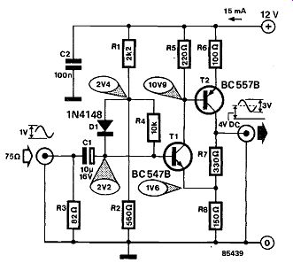
To raise the standard video signal of 1 Vpp to the level required by the television receiver, a preamplifier with a bandwidth of not less than 10 MHz is required. With careful construction of the present amplifier, this bandwidth is guaranteed, and should actually be of the order of close to 20 MHz. With a supply voltage of 12 V, the direct-voltage output is 4 V. If different supply voltages are used, the DC output is retained at that level by suitably altering the values of R, and R2 (which form a voltage divider). However, the supply voltage should not be lower than 10 V, nor higher than 15 V. The amplification depends on the ratio R7 : R8; if higher amplification is needed, the value of R7 should be in creased.
The respectable bandwidth is achieved by low value base and collector resistors: with this arrangement, even audio transistors may be used in this, essentially HF, circuit. In any case, the cut-off frequency of a BC 547 is 300 MHz, and that of a BC 557 is 150 MHz.
The input impedance is strictly determined by R3; its value of 82 ohm is near enough the required impedance, but if you really want to be a purist, there are 75 ohm resistors available at some stockists, or you can connect a 100 ohm resistor in parallel with a 330 ohm one.
-------------
301 VIDEO BUFFER/REPEATER
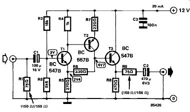
------------
This universal video amplifier is intended as a buffer/repeater in a long coaxial cable to keep the signal at a reasonable level. Its gain is about 6 dB.
The circuit is built from readily available components: some transistors and a few others.
The circuit consists of a two-stage amplifier, T1 and T2, and an emitter follower that functions as impedance converter. The bandwidth at-3 dB is not less than 20 MHz. Current consumption at a supply voltage of 12 V amounts to about 20 mA.
The power supply needs to be regulated to prevent lines and other noise on the screen.
The buffer/repeater is very suitable for being combined with the video selector featured elsewhere in this issue. The present circuit, with R, omitted, is then used as a buffer for the output of the inverter.
Its input impedance is then around 4 k-Ohm.
302 VIDEO DISTRIBUTION AMPLIFIER
The Type TEA5114 from Thomson-CSF comprises three electronic switches followed by a buffer/amplifier. Normally the voltage amplification is 2 (6 dB).
When the input voltage exceeds 1.2 Vpp, or when the output voltage exceeds 1.5 Vpp, an internal selector reduces the amplification to unity (0 dB).
The threshold of 1.2 Vpp is created with the aid of voltage divider It4-R5, which also forms the input termination of 75 ohm. Series resistors R1-R3 ensure 75 ohm output impedance for driving video equipment via standard coax cable. The TEA5114 can be used as a video source selector also, provided each input has its own 75 ohm termination network. The non-connected inputs should then be fitted with a coupling capacitor. Channel selection is effected by controlling the logic level at pins 10, 12 and 15.
Note that the logic 1 (high) level corresponds to + 2.5 V here.

-----
303 VIDEO SELECTOR
It is sometimes useful, or even necessary, to use the same screen for more than one video source. Some simple video selectors used for this purpose suffer rather badly from crosstalk. The present circuit does not have this drawback: the unused channel(s) is shorted out with a switch.

----------
When CH(annel) 1 is switched in, electronic switches ES, and ES2 are closed and ES4 is open.
The other channel(s) is effectively choked because ES5 and ES6 are both open and any residual crosstalk is shorted to earth by ES5. Each channel uses its own IC so that there is no risk of cross channel interference via the chips.
As the switches have a certain impedance in the on state, there will be some losses when the output is terminated into 75 ohm. It is, therefore, best to buffer the output; for instance, with the video buffer/repeater described elsewhere in this issue.
The input of the video selector must be terminated into 75 ohm. The-3 dB bandwidth is about 8 MHz.
Current consumption amounts to 1 . . . 2 mA depending on the supply voltage. A high supply voltage is preferable, because the electronic switches then have the lowest impedance in the on state.
-----
-------