With a multi-resistance box, just (just??) 64 resistors will give resistances in one ohm steps from 1R to 11MR.
by Vivian Capel
THE ELECTRONICS GENIUS who reels off designs at the drawing board without ever handling a soldering iron or any involvement in the subsequent result is a figment of popular imagination. When the theoretical design takes form as a prototype there almost inevitably follow modifications and component changes before things start working out as planned. This is euphemistically called the "empirical method of design", or in other words, try-it-and-see.
One reason for this is the tolerance of components, particularly semiconductors whose hfe (gain) values can range widely. Although designers of published circuits try to reduce the effect by various methods, and design for the mid-point in the hfe spread, constructors often find transistors at the edge or outside of the specified spread, and so run in to trouble.
-------------------------
Because of the resistor-intensive nature of this project, we have been unable to reconcile the requirements of (a) listing the resistors in order of part number (b) laying out the wiring diagram in a logical order and (c) giving a clear listing of how many of each to buy.
We have accordingly opted for the latter two as being the most useful, which is why your parts list begins with R37 instead of R1.
If you want them in order, look at Figure 2
RESISTORS
R37, 38 10R (2) R5, 6, 55, 56 20R (4) R21, 22 15R (2) R41, 42 100R (2) R9, 10, 59, 60 200R (4) R25, 26 150R (2)
Project
*Parts list
R35, 36, 45, 46 R3, 4, 13, 14, 53, 54, 63, 1k (4) 64 .. 2k (8) R19, 20, 29, 30 1 k5 (4) R39, 40 10k (2) R7, 8, 57, 58 20k (4) R23, 24 15k (2) R43, 44 100k (2) R11, 12, 61, 62 200k (4) R27, 28 150k (2) R33, 34, 49, 50, 51, 52 1R (6) R17, 18 1R5 (2) R2 1R8 (1) R1 2R2 (1) R47, 48, 65 1MR (3) R31, 32 1 M5 (2) R16 1M8(1) R15 2M2 (1)
MISCELLANEOUS
16 SPDT switches with center-off and long toggles; 3-pole jack socket; suitable case; solder; sleeving if desired.
------------------------------
Usually, changing appropriate resistor values will bring the circuit into line.
Often, too, experimental circuits need different values tried to achieve the desired result.
Here lies the snag. It is an immutable law that however good your stock of resistors is, the ones that you don't have are those values around the one that needs to be changed. So you have to resort to all manner of tricky and risky series-parallel arrangements to get the one you want.
The answer is a resistance box with which you can try different values by the flick of a switch until the optimum is found. Sounds straightforward enough, but when you start working out the practical details problems arise. To provide a full range of preferred E12 values you need 84 different values. It may not be too difficult to accommodate these, but the switching is another matter. Even with these, the range is not comprehensive, because the required value may be intermediate, needing one of the E24 values, or if the circuit is critical, still closer increments.
Percentage Increments At this point we will digress for the benefit of readers who may wonder, as I did once, why on earth the preferred range should include such awkward values as 4R7, 5R6, 6R8 and so on; why not round figures such as they used in the early days? The answer is that each value is approximately 20% increase over the previous one. The effect on most circuits of substituting the next higher or lower value will be proportionately the same. Hence going from 1 R0 to 1 R2 is the same as going from 6R8 to 8R2, a 20% increase.
There are twelve values in each decade, and seven decades from 1 ohm to 01 megohms, giving 84 values. In the case of the E24 series, the increases are about 10%, resulting in 24 values per decade and a total of 168.
A further digression: as anyone who has worked at servicing domestic electronic equipment will know, certain values occur far more frequently then others. Decades of 3R3, 4R7, and 6R8, occur much more often than the remaining ones, while 1 R5 and 8R2 are particularly rare. Why is this? Is it just how the design values work out? Or more prosaically, do the manufacturers get resistors more cheaply by buying them in huge quantities of a few values? I would be interested to hear any opinions on this.
Boxing Clever
Because of the large number of values in the range, many resistance boxes compromise so that various values are omitted. Those included are the ones deemed to be the most useful, but we all know which are the values we most likely will want--the missing ones! How then can we include all the E24 values without using over a hundred resistors and having an impractical array of switching? To start, we can base our box around the fact that any value from 1 to 10R can be obtained from just four resistors, of values 1 R, 2R, 3R, and 4R, in various combinations. To do this, they are wired in series with a switch connected across each one. With all switches closed there is zero resistance in circuit as all are shorted out, but opening any switch will add the value of its resistor to the total.
Thus four resistors, and four switches, for each decade will give every value from 1R up to 11,111,110R or 11MR plus some. This looks rather more practical, but even so it needs 28 switches which is rather unwieldy.
These switches can be reduced by arranging the switching in two ranges, a x1 and x1,000. This does not halve the switches required, because we need four for each decade. Either we must sacrifice a decade, making six, having three in each range with a total of twelve switches; or we must have four decades for each, needing sixteen switches and duplicating one decade. As a comprehensive tool was required, the latter course was chosen.
One method of obtaining the two ranges is to use double-pole switches, each pole connected in series with one of two loops of resistors. A further switch is then included as the range switch to select either high or low values. There is at least one commercial resistance box that is designed along these lines.
There is, though, one snag with this arrangement. When switched to the higher range, values can only be changed in increments of 1,000R. At the highest decade, the megohm range, this is not much of a drawback, but at the lowest one, the thousands of ohms, it means that preferred values cannot be obtained, only round values. If, though, the duplicated decade is included here, these values can be achieved from the highest decade of the lower range. So the worst effect is with the second lowest decade on the high range, the tens of thousands. While a resolution of a thousand ohms does not interfere with the obtaining of any of the preferred values, it does restrict the fine degree of change that would otherwise be obtainable, and so too, although to a lesser extent, the next decade up.
This unit was designed to overcome this snag, and incidentally is also simple in that no range switch is required and single-pole double throw switches are used instead of double-pole, involving wiring to three instead of four terminals.
A center-off position is required, but this does not add to the constructional or wiring complexity.
One Ohm Steps
With this unit, both ranges can be used simultaneously so that if required changes of one ohm can be made while on the megohm range. The only limitation which does prevent every value in one ohm steps from being achieved is the fact that a switch obviously cannot be used in two positions at the same time. Compared to those attainable, the unobtainable ones are very few and are reduced further by the duplicated decade.
Each switch has two resistor values associated with it, the low one connected across the two static contacts and the x1,000 value across one static and the moving contact. When the switch is up, the high value is shorted out and the low value is out of circuit, so the result is zero ohms. With the switch in the mid-off position, the high value resistor is now introduced into the circuit. Going to the low position places the low value in parallel with the high and thus obtains the low range value.
An obvious objection here is that paralleling the resistors on the low range decreases the resistance thereby giving an inaccurate value for the low range.
However, the shunting resistor is a thousand times higher in value, which by a simple Ohm's law calculation drops the value by just under a thousandth. If the closest resistor tolerance generally available, which is 1%, are used, the error caused by shunting is less than a tenth of the resistor tolerance. Hence there will be a greater error due to tolerance than due to paralleling the two values. In practice then, this affords a practical method of switching with minimum complication and with insignificant error.
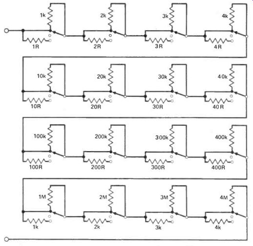
Figure 1. The circuit. Every switch has two connections and a center off position
(the fact that 11 of the switches are shown connected is purely an eccentricity
of the drawing). It is by combining these connections that a variety of resistances
is obtained.
To summarize, then, as every whole number from 1-10 can be obtained by combining the numbers 1-4, only four values are required for each decade.
Two resistors are used for each value except 1 ohm and 1 megohm to obtain the required value and double the power rating. All switches are connected in series and each has three states: (1) a through circuit giving zero ohms; (2) (center off) the high value is introduced, and (3) the low value is shunted across it. As the ratio between high and low values is 1,000/1, the error is a tenth of resistor tolerance and insignificant.
Components
Ideally, resistors of 1, 2, 3, and 4 ohms and their decades of 1% tolerance and 1 watt rating should be used. Furthermore, they should be of low temperature coefficient and possess high stability.
With these, the box can be relied on to give accurate values under a wide variety of conditions and continue to do so for many years.
Unfortunately, the ideal components are not generally available so we have to make do with the best that can be obtained. As accuracy is a major requirement, 1% tolerance was chosen except for the lowest decade for which 2% was the best available. For the highest decade no better than 5% could be found, though when actually measured they were well within the tolerance. (but see Shop--Ed.) For the main ranges metal film resistors were used. These are the only ones obtainable in 1% tolerance, and as a bonus they have low temperature coefficient and high stability. For the values needed though, only .25 watt rating or .4 watt commercial are avail able. This may be adequate for most purposes, and with more than one value usually selected by the switching the wattage rating is increased, but it could pose a limitation on use especially when just a single value is in circuit.
It was therefore decided to use a choice of parallel or series resistors for each value to double the rating. The components are not large or expensive, so this is no great drawback and further more, two resistors have to be used anyway to obtain the correct value for 4R and its decades.
The chosen range of components must be available in the E24 series as most of the values are E24 preferred ones. The make-up of values is as follows: For 1R, two 2Rs are used in parallel; for 2R, two 1 Rs are wired in series; for 3R, we use two 1 R5s in series, and for 4R two 2Rs in series.
For the lowest decade, thick film metal glaze resistors at 2% came closest to the required characteristics. Unfortunately a 2R value is not available in this range. To obtain a higher wattage therefore, four 1R was used for the 1R value, connected in series-parallel. Two 1R in series for the 2R value as with the other ranges, also two 1R5s for the 3R value. In the case of the 4R value, 1 R8 and 2R2 in series serves the purpose.
A similar combination can be used for the highest decade except that a single 1 MR resistor is used to provide the value. High wattage dissipation is unlikely to be required at that value. Some 700 volts would need to be applied to dissipate half a watt. A pair is needed in the other positions to obtain the required values. Hi-stability carbons at 5% tolerance and half-watt rating are used.
As for the switches, SPDT units with center-off position are required as previously mentioned. They were chosen with long toggles, because with sixteen switches of miniature type, it would otherwise be easy to overlook a switch in the wrong position. The long toggles enable the setting of all switches to be recognized at a glance.

-------- Figure 2. The wiring diagram for the Resistance Box. The links
between one switch and the next can be made, with care, using the long uncut
leads on the appropriate resistor. In this way no extra wire needs to be used
(although you can do so if you prefer).
Construction
Some thought was given to the arrangement of the switches to give the most logical and natural mode of use.
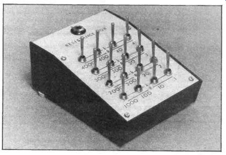
Four rows of four seemed the obvious configuration, each row for one decade, but which is the best way for them to run, from side-to-side, top-to-bottom, or bottom-to-top of the panel? The arrangement chosen, as can be seen in the photo, is from bottom-to-top, with the lowest values at the bottom. Then, the next decision was how to order the decades, from right-to-left, or left-to-right. For this the choice was from right-to-left, starting with the lowest decade on the right.
The reason for these choices was that in reading or thinking of a given value we encounter the highest decades first followed by the lower ones. So, as we read from left-to-right, it is natural to set the high values at the top left and work across and downward. Thus, if we want to obtain the value of 3M25, we set the left hand column to 3, the next to 2 and the third to either 2 and 3 or 1 and 4. The switches can of course be arranged any way the constructor wishes, and indeed most commercial boxes are laid out differently, however, this seemed to be the most logical, and subsequent use has confirmed its practicality.
The next consideration was the output terminals, of which the constructor has a variety to choose from. One possible use envisaged for the unit is the substitution of components in amplifier circuits where hum induced into the connecting leads could be a problem, for example, changing the values of an input load resistor to determine effect on frequency response and other parameters. Hence it seemed desirable to make provision for screening the leads. Using a single screened lead would mean that one leg of the circuit would be connected via the screen, hence should be earthed.
However, the resistor being substituted may not be connected to chassis in the equipment under test. To avoid problems of this nature, twin screened cable is used, hence the screen can be earthed to the chassis, being independent of the circuit. Alternatively it can be left floating if the circuit under test is not critical.
The output connector chosen, there fore, is a three-pole jack socket, the earth connection being taken to the metal control panel. This is easily done by clamping a bare wire under the nearest switch to the output socket.
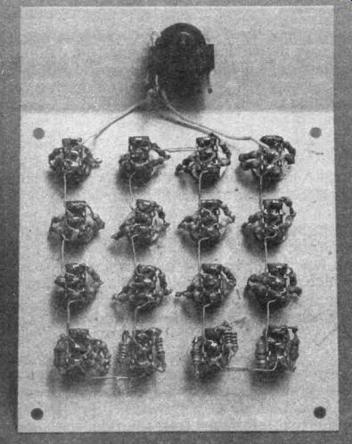
All resistors are wired directly to the switches, but double check that you have the right resistors for the correct switch. It is easy to get them wrong! Do not crop all the wires off after soldering; one from the appropriate tag should be long enough to reach the next switch.
Sleeving can be used on these lengths if desired, but they are so short and rigid that it is not really necessary; those on the prototype were left bare. Just ensure that they are bent away from other tags and also from the metal body of the switch.
As all switches are in series it doesn't matter what sequence they follow in the circuit. Hence they can be wired in the most convenient manner. The arrangement shown in Figure 2 is the most straightforward, and the resistor wires can be used to link the adjacent columns just as they do adjacent switches. No extra wire is therefore needed at all except from the final switches to the output socket.
A resistance box is one of those gadgets that is inexpensive and has obvious virtues, yet its acquisition is often postponed, probably because of the limitations of available units. Once built. you will wonder how you managed without this device. Well, what about a comprehensive capacitance box to match? We are working on it, so watch this space!
----------
-----------
SHOP
As the author recommends, the closer you can come to 1W, 1% rated resistors, the more stable and accurate your box will be. However, 5% 0.4W resistors will do the job adequately most of the time. Either carbon or metal film will do.
Carbon film 1W, 5% resistors are available from Maplin in all ranges except the 1 to 8R2 range, 0.4W, 1 metal film resistors are available for all decades. This is the best choice we can find, and actually represents a slight improvement over the author's own specification.
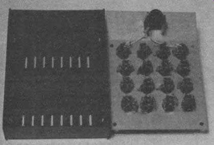
The box used is Bimbox 6005, with a sloping front, ventilation slots below, and small rubber feet. Any suitable box can be substituted; slots can be cut and feet added, but make sure before you start that you are allowing enough space for all your switches AND the clutch of resistors, leads and solder around them. Be generous rather than niggardly to give yourself more room to work.
As for the switches. Cirkit (tel: 0992 444111) do an SPDT toggle switch with a standard toggle, no 53.00202. The author has used Altai STM10 long toggle switches: nice if you can find them; if not, standard toggle will do, but again, remember what we said about leaving yourself space to operate them easily.
The cost of the project, using standard rather than special components, should be around £ (x 1.4 USD) 17, with the switches being the most expensive sector. It is worth casting around to see if you can find cheaper switches (the Cirkit ones are around 75p each). Don't try to substitute a different kind, however.
Also see: SECRETS OF SOLDERING
COMPONENTS FROM THE INSIDE OUT-- We unroll some capacitors.